coolant MITSUBISHI ECLIPSE 1991 Owner's Guide
[x] Cancel search | Manufacturer: MITSUBISHI, Model Year: 1991, Model line: ECLIPSE, Model: MITSUBISHI ECLIPSE 1991Pages: 1216, PDF Size: 67.42 MB
Page 374 of 1216
9-90ENGINE <2.0L DOHC Engine> - Cylinder Head Gasket
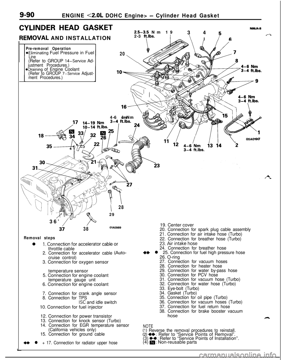
CYLINDER HEAD GASKETNOSJA-S2.5-3.5 Nm 19
3 4 K
REIVIOVAL AND INSTALLATION2-3 ft.lbs.\ I i-6
Pre-removal Operation*Eliminating Fuel Pressure in Fuel20Line1\(Refer to GROUP 14-Service Ad-justment Procedures.)eDraining of Engine Coolant(Refer to GROUP 7-Service Adjust-
ment Procedures.)
,,vs4-6 Nm
’
II28
2936’
/w,=
3i38OlAO5.69
Removal stepsl
1. Connection for accelerator cable orthrottle cable
2. Connection for accelerator cable (Auto-
cruise control)3. Connection for oxygen sensor
temperature sensor
5. Connection for engine coolant
temperature gauge unit6. Connection for engine coolant
7. Connection for crank angle sensor
8. Connection for TPS
ISC and idle switch
10. Connection for fuel injector
12. Connection for power transistor
13. Connection for knock sensor (Turbo)
14. Connection for EGR temperature sensor
(California vehicles only)
15. Connection for ground cable
+e l + 17. Connection for radiator upper hose
/\05ADl9019. Center cover
20. Connection for spark plug cable assembly
21. Connection for air intake hose (Turbo)
22. Connection for breather hose (Turbo)
23.Airintakehose24. Connection for breather hose+e l 25. Connection for fuel high pressure hose26. O-ring
27. Connection for vacuum hoses
28. Connection for heater hose
29. Connection for water by-pass hose
30. Connection for PCV hose
31. Connection for vacuum hose (Turbo)
32. Connection for water hose (Turbo)
33. Eye-bolt (Turbo)
34. Gasket (Turbo)
35. Connection for oil pipe (Turbo)
36. Connection for vacuum hoses (Turbo)
37. Connection for fuel return hose
38. Connection for brake booster vacuum
hoseA
NOTE(1) Reverse the removal procedures to reinstall.(2) +I) : Refer to “Service Points of Removal”.
(3) ~~ : Refer to “Service Points of Installation”.
(4) m : Non-reusable parts
Page 375 of 1216
ENGINE <2.0L DOHC Engine> - Cvlinder Head Gasket9-91-_
-2.5-3.5 Nm
2-3
ft.lbs.
I
/
So-100 Nm65-72 ft.lbs.
‘L-\
925-30 Nm
18-22
ft.lbs.55-65 Nm
40-47 ftJbs.27
m43
\
ft.lbs.
29-43
ft.lbs.
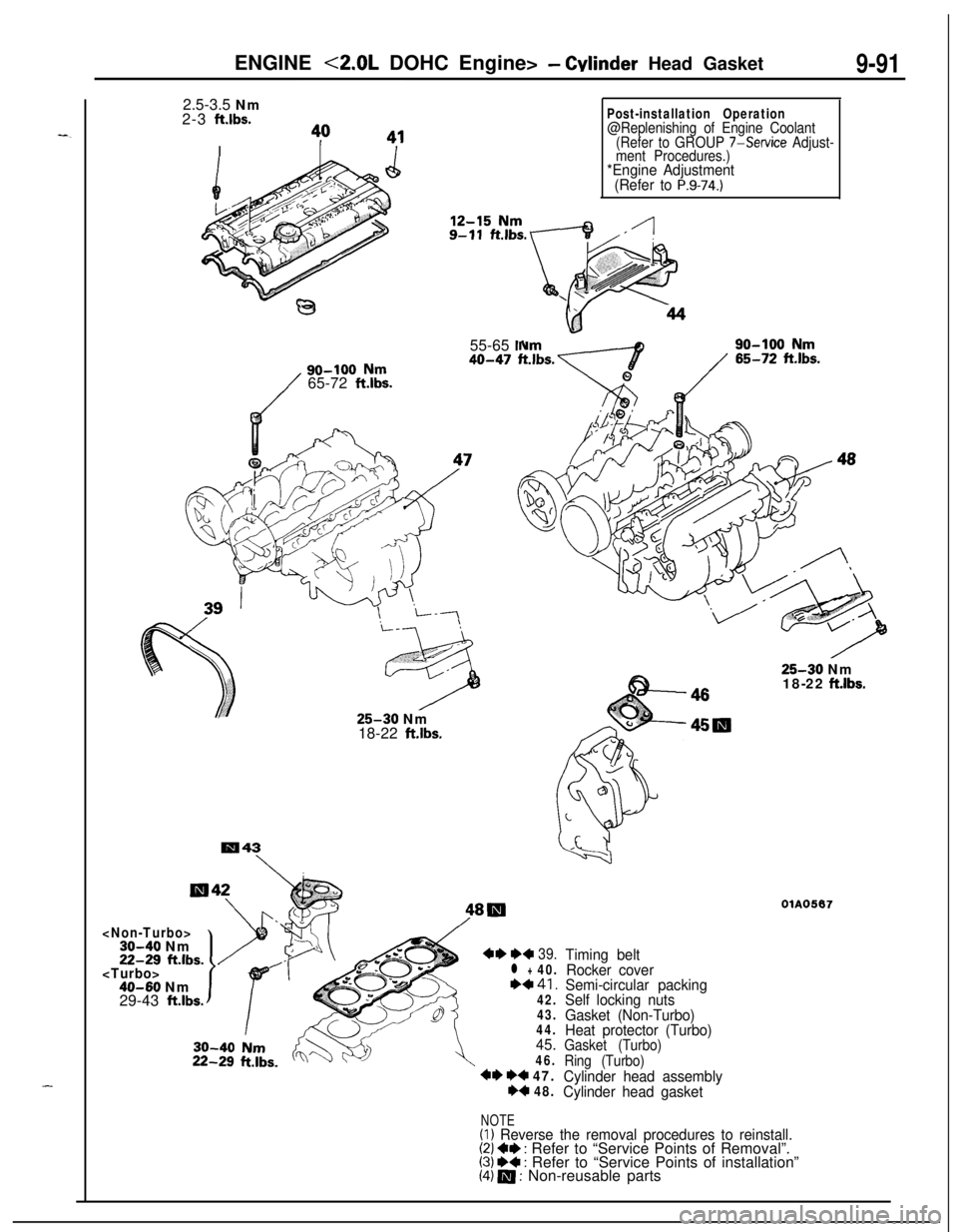
Post-installation Operation@Replenishing of Engine Coolant
(Refer to GROUP 7-Service Adjust-
ment Procedures.)
*Engine Adjustment
(Refer to P.9-74.)
48046
45m
4*+439.l +40.+441.42.
43.
44.
22-29 ft.lbs.
45.46.
4* +4 47.+4 48.25-30 Nm
18-22
ft.lbs.
OlA0567
Timing belt
Rocker cover
Semi-circular packing
Self locking nuts
Gasket (Non-Turbo)
Heat protector (Turbo)
Gasket (Turbo)
Ring (Turbo)
Cylinder head assembly
Cylinder head gasket
NOTE(I) Reverse the removal procedures to reinstall.(2) 4e : Refer to “Service Points of Removal”.(3) ++ : Refer to “Service Points of installation”(4) m : Non-reusable parts
Page 377 of 1216
ENGINE <2.0L DOHC Engine> - Cylinder Head Gasket9-93
DlADD3fFront of
engine+Exhaust side
OlR0391Cylinder
he/d-Ani-circularpackingSERVICE POINTS OF INSTALLATIONNOSJDDls
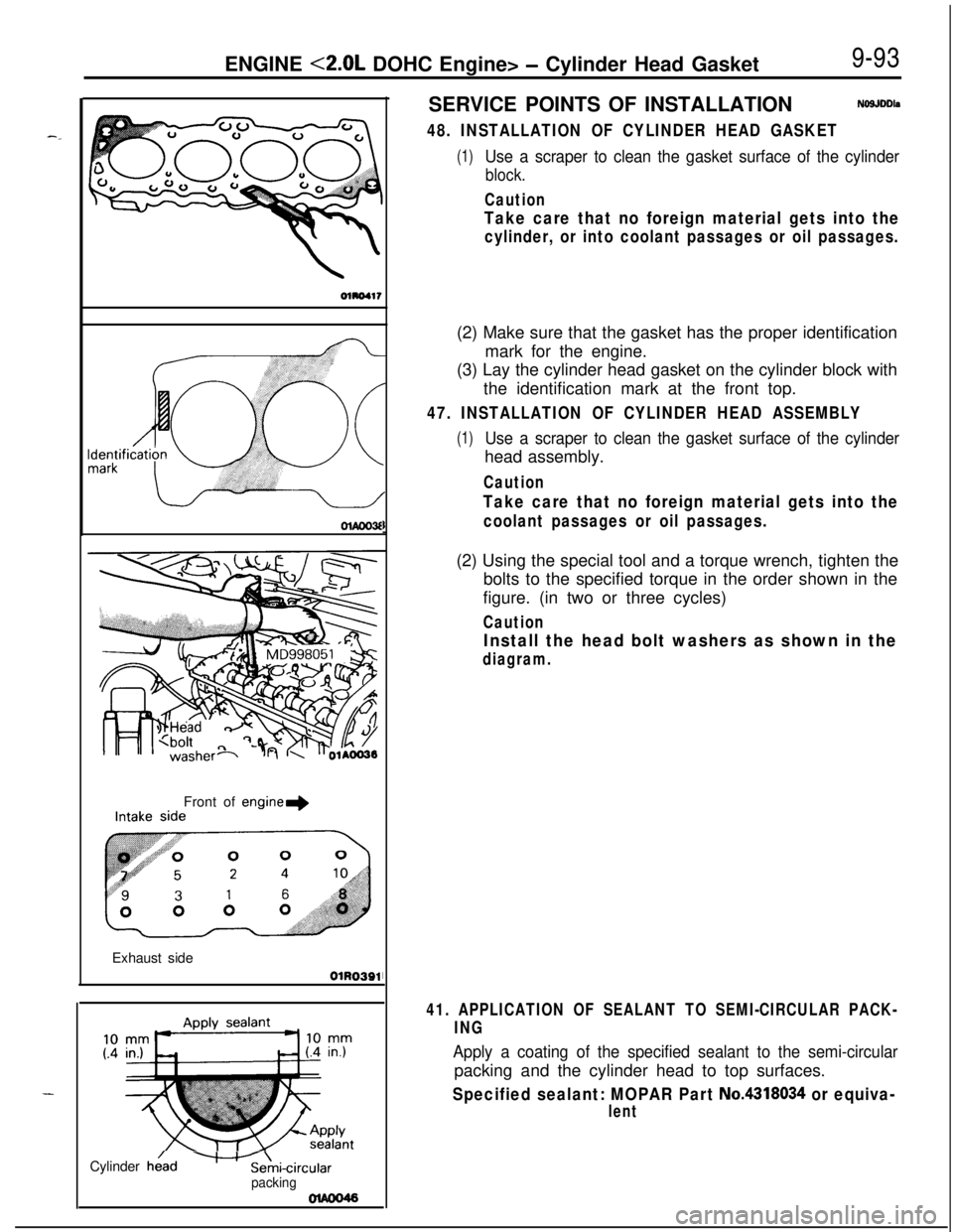
48. INSTALLATION OF CYLINDER HEAD GASKET
(1)Use a scraper to clean the gasket surface of the cylinder
block.
Caution
Take care that no foreign material gets into the
cylinder, or into coolant passages or oil passages.(2) Make sure that the gasket has the proper identification
mark for the engine.
(3) Lay the cylinder head gasket on the cylinder block with
the identification mark at the front top.
47. INSTALLATION OF CYLINDER HEAD ASSEMBLY
(1)Use a scraper to clean the gasket surface of the cylinderhead assembly.
Caution
Take care that no foreign material gets into the
coolant passages or oil passages.(2) Using the special tool and a torque wrench, tighten the
bolts to the specified torque in the order shown in the
figure. (in two or three cycles)
Caution
Install the head bolt washers as shown in the
diagram.
41. APPLICATION OF SEALANT TO SEMI-CIRCULAR PACK-
ING
Apply a coating of the specified sealant to the semi-circularpacking and the cylinder head to top surfaces.
Specified sealant: MOPAR Part No.4318034 or equiva-
lent
Page 397 of 1216
ENGINE <2.0L DOHC Engine> - Cylinder Head and Valve9-l 13
.
.
a Front of engine (Timing belt side)
6EN0211
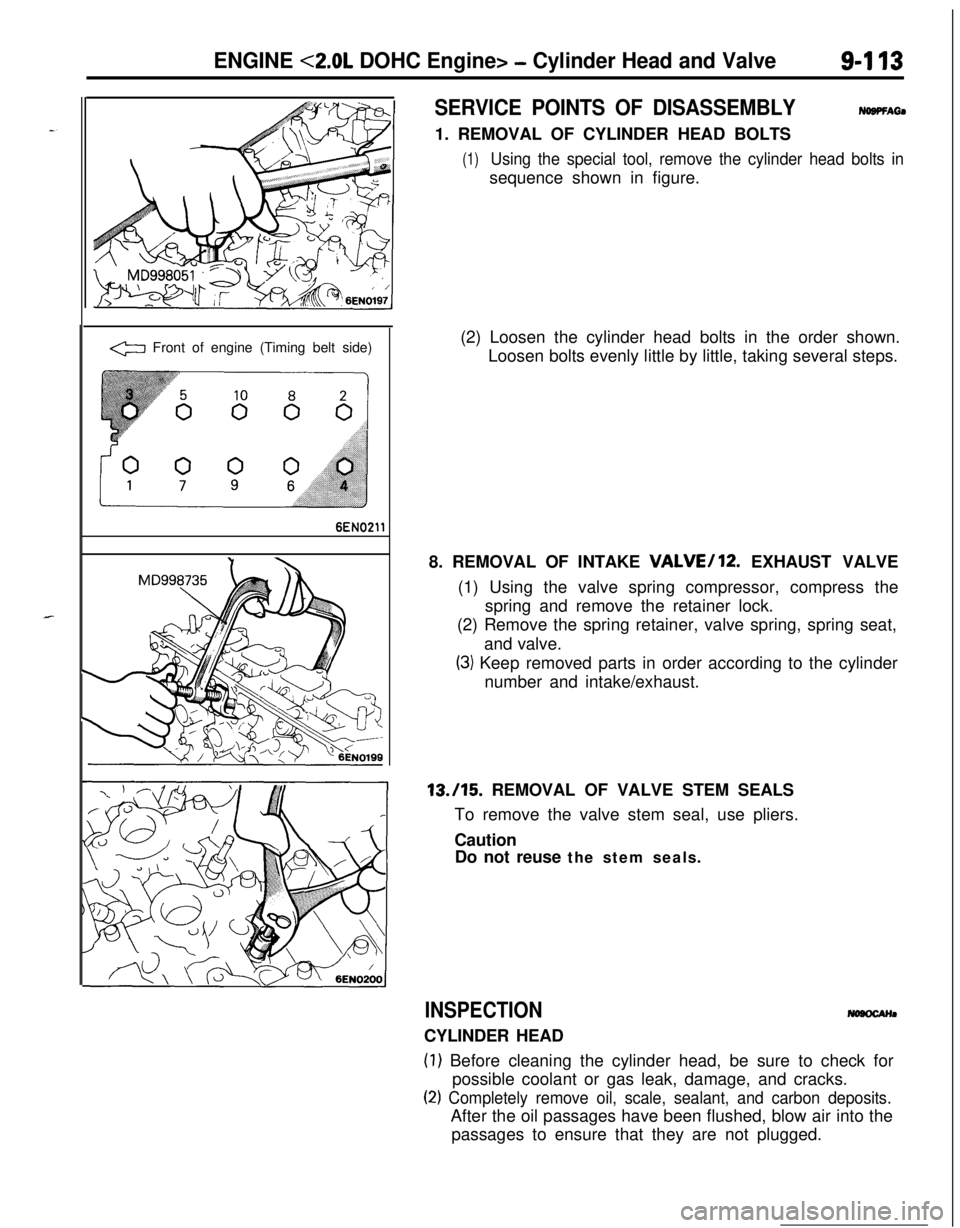
SERVICE POINTS OF DISASSEMBLYNOBPFAti1. REMOVAL OF CYLINDER HEAD BOLTS
(1)Using the special tool, remove the cylinder head bolts insequence shown in figure.
(2) Loosen the cylinder head bolts in the order shown.
Loosen bolts evenly little by little, taking several steps.
8. REMOVAL OF INTAKE
VALVE/12. EXHAUST VALVE
(1) Using the valve spring compressor, compress the
spring and remove the retainer lock.
(2) Remove the spring retainer, valve spring, spring seat,
and valve.
(3) Keep removed parts in order according to the cylinder
number and intake/exhaust.13./15. REMOVAL OF VALVE STEM SEALS
To remove the valve stem seal, use pliers.
Caution
Do not reuse the stem seals.
INSPECTIONCYLINDER HEAD
(1) Before cleaning the cylinder head, be sure to check for
possible coolant or gas leak, damage, and cracks.
(2) Completely remove oil, scale, sealant, and carbon deposits.After the oil passages have been flushed, blow air into the
passages to ensure that they are not plugged.
Page 435 of 1216
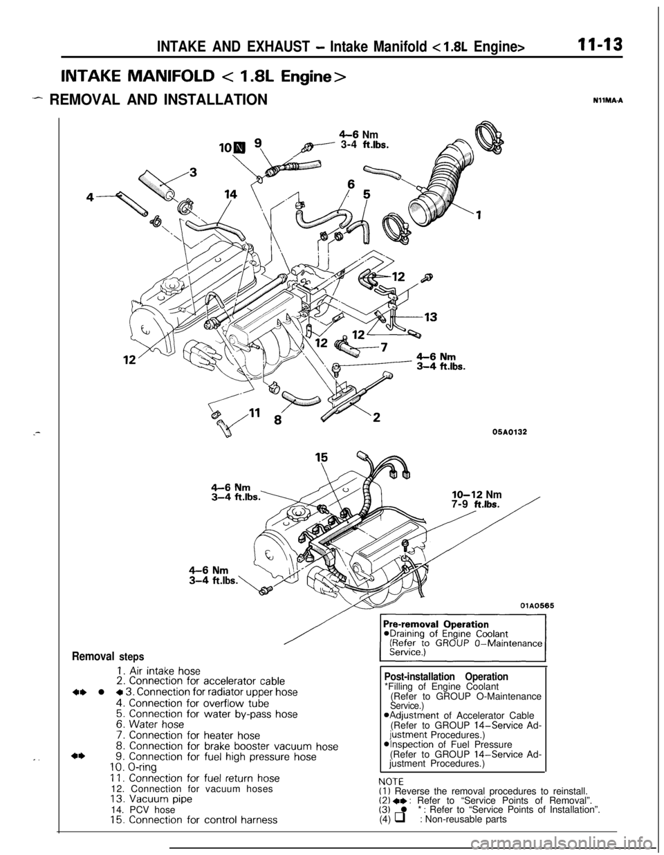
INTAKE AND EXHAUST - Intake Manifold < 1.8L Engine>
INTAKE MANIFOLD < 1.8L Engine>
.- REMOVAL AND INSTALLATION
11-13NllMA-A.-
. .
4-6 Nmpy---- 3-4 ft.lbs.
B05A0132
Removal steps
1. Air intake hose2. Connection for accelerator cable
4, l + 3. Connection for radiator upper hose
4. Connection for overflow tube5. Connection for water by-pass hose6. Water hose
7. Connection for heater hose8. Connection for brake booster vacuum hose9. Connection for fuel high pressure hose10. O-ring
11. Connection for fuel return hose12. Connection for vacuum hoses
13. Vacuum pipe14. PCV hose
15. Connection for control harness
IO-12 Nm7-9 ft.lbs.
OlA0565
Post-installation Operation
NfJTF*Filling of Engine Coolant
(Refer to GROUP O-Maintenance
Service.)aAdjustment of Accelerator Cable
(Refer to GROUP 14-Service Ad-
justment Procedures.)*Inspection of Fuel Pressure
(Refer to GROUP 14-Service Ad-
justment Procedures.)
I.” IL(1) Reverse the removal procedures to reinstall.(2) +* : Refer to “Service Points of Removal”.(3) l * : Refer to “Service Points of Installation”.
(4) q : Non-reusable parts
Page 439 of 1216
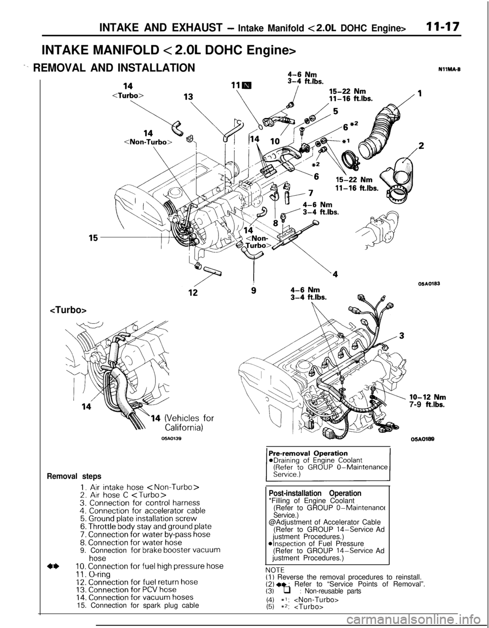
INTAKE AND EXHAUST - Intake Manifold <2.0L DOHC Engine>I I-1.7INTAKE MANIFOLD
< 2.0L DOHC Engine>
^- REMOVAL AND INSTALLATION4-6 Nm
ft.lbs.
14 (Vehicles for
05AO139
i34-6 Nm3-4 ftlbs.
Removal steps
I. Air intake hose
7. Connection for water by-pass hose8. Connection for water hose9. Connection for brake booster vacuum
4*
hose10. Connection for fuel high pressure hose
11. O-ring12. Connection for fuel return hose13. Connection for PCV hose14. Connection for vacuum hoses15. Connection for spark plug cable
Post-installation Operation*Filling of Engine Coolant
(Refer to GROUP 0-Maintenance
Service.)@Adjustment of Accelerator Cable
(Refer to GROUP
14-Service Ad
justment Procedures.)
@Inspection of Fuel Pressure
(Refer to GROUP 14-Service Ad
justment Procedures.)
NOTFNllMA-B
OSAO133
lo-12 Nm7-9 ft.lbs.
05AOl89
,.-.-(I) Reverse the removal procedures to reinstall.(2) +e : Refer to “Service Points of Removal”.(3) q : Non-reusable parts
1:;*I:
Page 442 of 1216
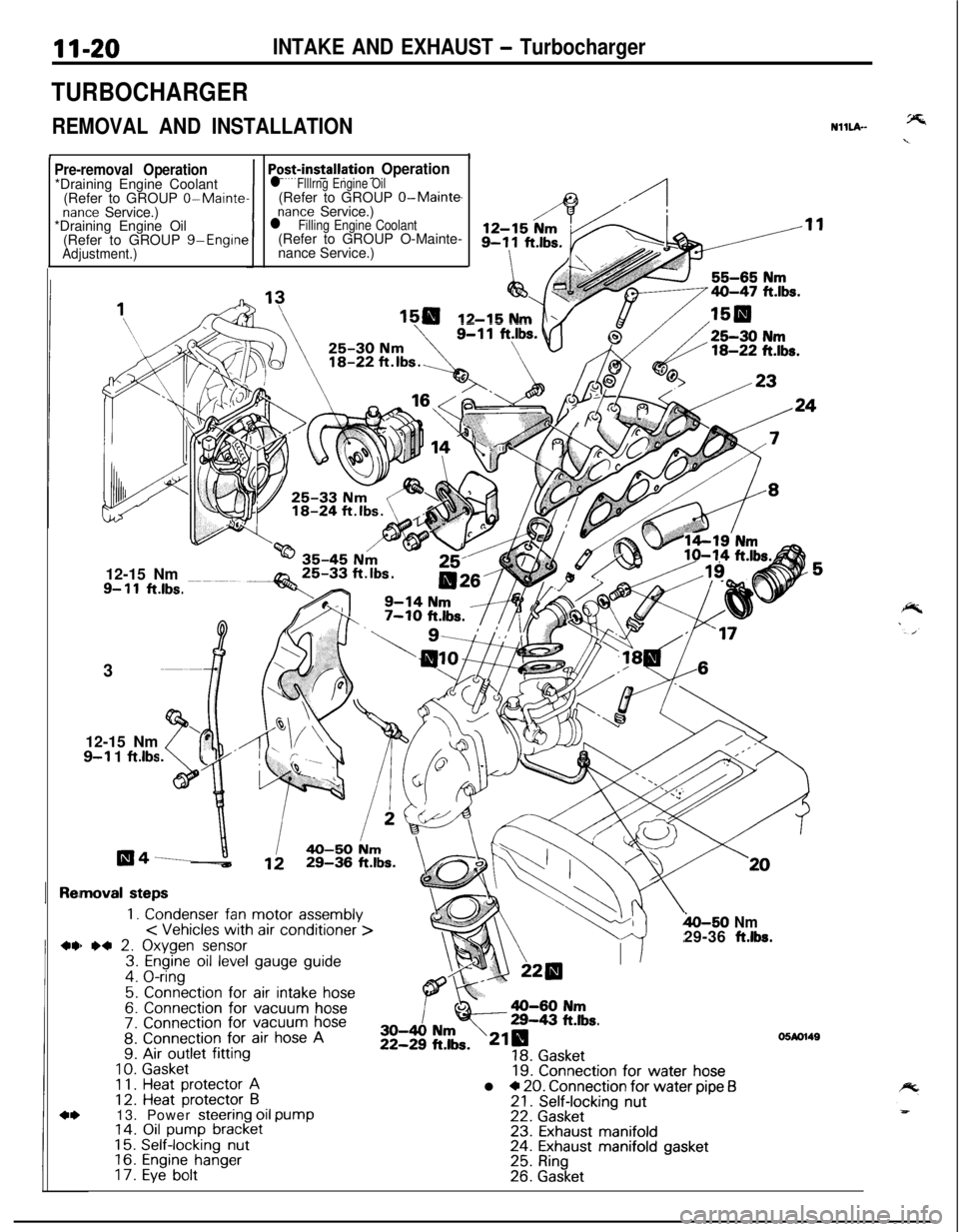
II-20INTAKE AND EXHAUST - Turbocharger
TURBOCHARGER
REMOVAL AND INSTALLATION
II
NHLA-
Pre-removal Operation*Draining Engine Coolant
(Refer to GROUP
0-Maintenance Service.)
*Draining Engine Oil
(Refer to GROUP g-Engine
Adjustment.)1
Po+installation Operationl Flllrng Engine Oil(Refer to GROUP O-Main@
nance Service.)l Filling Engine Coolant(Refer to GROUP O-Mainte-
nance Service.)
12-15 Nm12-15 Nm
9- 11ft.lbs.3
12-15 Nm
9-l 1 ftlbs
moval steps
1. Condenser fan motor assembly< Vehicles with air conditioner >) *4 2. Oxygen sensor3. Engine oil level gauge guide4. O-ring
5. Connection for air intake hose6. Connection for vacuum hose7. Connection for vacuum hose8. Connection for air hose A9. Air outlet fitting
10.Gasket1 1.Heat protector A12. Heat protector B13. Power steering oil pump14. Oil pump bracket15.Self-locking nut16.Engine hanger17.Eye bolt
h-50 Nm29-36 ft.lbs.
19. Connection for water hosel * 20. Connection for water pipe f321. Self-locking nut22. Gasket23. Exhaust manifold24. Exhaust manifold gasket25. Ring26. Gasket
05M1149
Page 450 of 1216
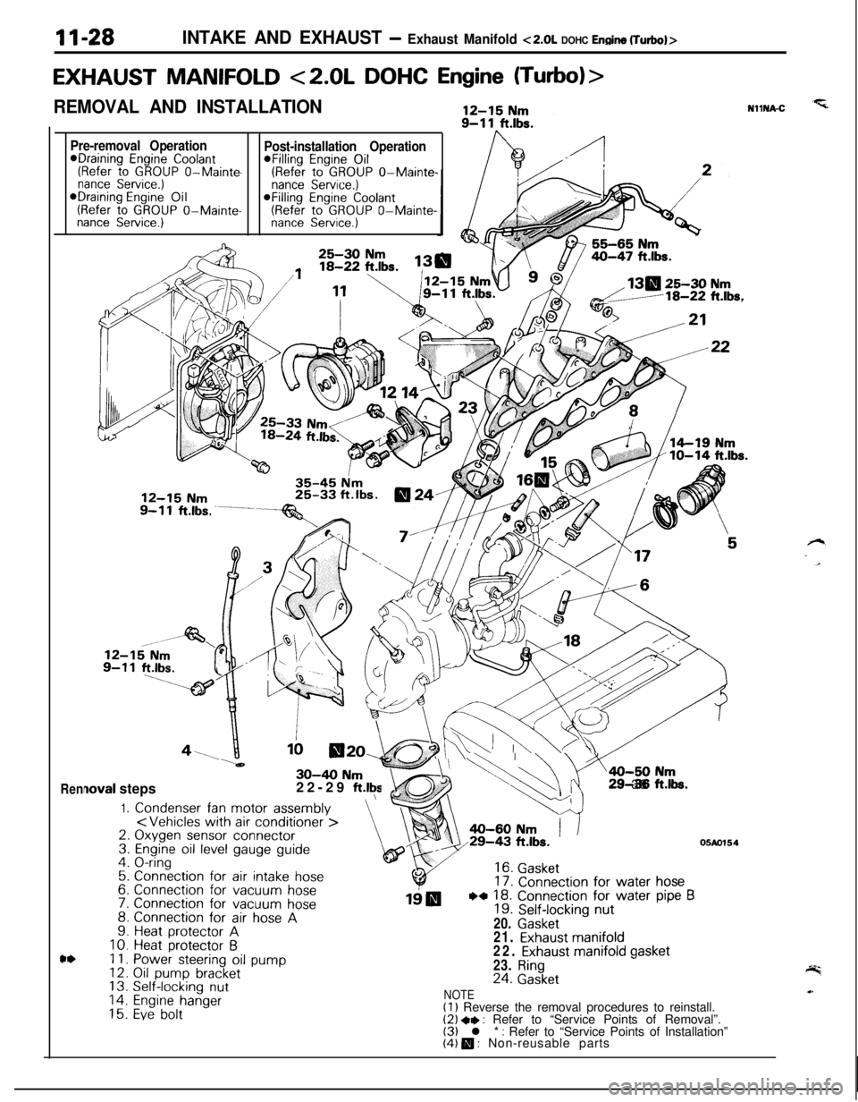
11-28INTAKE AND EXHAUST - Exhaust Manifold ~2.0~ DOHC Enoine (Turbo)>
EXHAUST MANIFOLD <2.0L DOHC Engine (Turbo)>
REMOVAL AND INSTALLATION
Pre-removal Operation*Draining Engine Coolant(Refer to GROUP O-Mainte-nance Service.)*Draining Engine Oil(Refer to GROUP O-Mainte-nance Service.)
Rennova1 steps
1.Condenser fan motor assembly
\30-40 Nm22-29 ft.lty3. & (
EJ\\=a-50 N
4 .ri29-38 ftk.
,
Post-installation Operation@Filling Engine Oil(Refer to GROUP O-Mainte-nance Service.)@Filling Engine Coolant(Refer to GROUP O-Mainte-nance Service.)NllNA-C
130 25-30 Nmd/18-22 ft.lbs.
;:4.
s5:7.
::10.Ii.12.13.14.15.
Connection for air intake hose
Connection for vacuum hoseConnection for vacuum hoseConnection for air hose AHeat protector AHeat protector 6Power steering oil pumpOil pump bracketSelf-locking nut
Engine hangerEve bolt
16. Gasket17. Connection for water hose
19IBWI 18. Connection for water pipe B19. Self-locking nut20.
Gasket
05Ao15421.
Exhaust manifold22. Exhaust manifold gasket23.
Ring24. Gasket
NOTE(1) Reverse the removal procedures to reinstall.(2) +, : Refer to “Service Points of Removal”.(3) l * : Refer to “Service Points of Installation”(4) m : Non-reusable parts
Page 455 of 1216
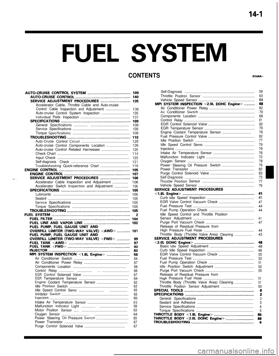
14-IFUEL SYSTEM
CONTENTS
AUTO-CRUISECONTROLSYSTEM...........................................109AUTO-CRUISECONTROL.......................................................140SERVICEADJUSTMENTPROCEDURES..............................135Accelerator Cable, Throttle Cable and Auto-cruise
ControlCableInspectionandAdjustment........................136Auto-cruise
ControlSystemInspection.............................135lndrvrdualPartsInspection..................................................137SPECIFICATIONS.....................................................................109GeneralSpecifications.......................................................109ServiceSpecifications
.........................................................109Torque Specrfications..........................................................109TROUBLESHOOTING...............................................................110Auto-CruiseControlCircurt................................................128Auto-cruise
ControlComponentsLocation........................126Auto-cruise Control Related Harnesses
.............................125Check Chart
........................................................................114Input Check.........................................................................123Self-diagnosis
Check..........................................................121Troubleshootrng
Quick-referenceChart..............................110ENGINECONTROL.......................................................................105ENGINECONTROL..................................................................107--SERVICEADJUSTMENTPROCEDURES..............................106Accelerator Cable Inspection and Adjustment..................106Accelerator Switch Inspectron and Adjustment................106SPECIFICATIONS.....................................................................105Lubricants.............................................................................105Sealant.................................................................................105ServiceSpecifications
..........................................................105TorqueSpecifications..........................................................105TROUBLESHOOTING...............................................................105FUELSYSTEM..............................................................................2FUELFILTER............................................................................104FUELLINEANDVAPORLINE..............................................102FUEL PUMP, FUEL GAUGE UNIT ANDOVERFILL LIMITER(TWO-WAY VALVE)
Switch........................................................64Air Conditioner Power Relay
..............................................67Components
Location......................................................56
ControlRelay
.................................................................66EGRControlSolenoidValve...............................................67EGRTemperatureSensor..................................................64Engine Coolant Temperature Sensor
.................................62IdlePosrtionSwitch
...........................................................63IdleSpeedControlServo
.............................
....................65InhibitorSwitch....................................................................65hjeCtOrS................................................................................65IntakeAirTemperatureSensor..........................................6’2MalfunctionlndtcatorLight
..........................................58MotorPosition
Sensor................................................63OxygenSensor
.................................................................64Power Steering 011 Pressure Swatch...........................65PowerTransistor
................................................................67PurgeControlSolenoidValve.........................................67
Self-Diagnosis.......................................................................
ThrottlePositronSensor.....................................................
Vehicle Speed Sensor.........................................................MPI
SYSTEMINSPECTION<2.0L DOHCEngine>...........Air Conditioner Power Relay..............................................
Arr Conditioner Swatch........................................................
Components Location
.........................................................
Control
Relay.......................................................................
EGR Control Solenoid Valve...............................................
EGR Temperature Sensor
...................................................
Engine Coolant Temperature Sensor
.................................Fuel Pressure Control Valve...............................................
Idle Position Switch
............................................................
Idle
SpeedControlServo...................................................Injectors
................................................................................
Intake Air Temperature Sensor..........................................
Malfunction Indicator Light.................................................
Oxygen Sensor
....................................................................
Power
Steering
OilPressureSwitch.................................Power Transistor
.................................................................
Purge Control Solenoid Valve.............................................
Self-Diaanosis.......................................................................
58
63
2382
79
688182
79
7682
77
79
79
76
727879
82
8273ThrottletiPosition Sensor
.....................................................77Vehicle Speed Sensor
.........................................................79SERVICE ADJUSTMENT PROCEDURES<1.8L Engine>........................................................................41Curb Idle Speed Inspection
................................................41EGR Valve Control Vacuum Check....................................47Fuel Pressure Test
..............................................................44Fuel Pump Operation Check
..............................................44Idle Speed Control and Throttle Position
Sensor Adjustment
..............................................................
41Purge Port Vacuum Check
.................................................47Release of Residual Pressure from
High Pressure Fuel Hose
...................................................
44Throttle
Body(Throttle Valve Area)Cleaning....................43SERVICE ADJUSTMENT PROCEDURES<2.0LDOHCEngine>............................................................48Basic Idle Speed Adjustment
.............................................
48
Curb Idle Speed Inspection
................................................48EGR Valve Control Vacuum Check....................................55Fuel Pressure Test
..............................................................52Fuel Pump Operation Check
..............................................51Idle Position Switch Adjustment........................................52Purge Port Vacuum Check
.................................................55Release of Residual Pressure from
High Pressure Fuel Hose
...................................................51Throttle Body (Throttle Valve Area) Cleaning....................51ThrottlePositionSensorAdjustment.................................50SPECIALTOOLS......................................................................6SPECIFICATIONS.....................................................................2GeneralSpecifications.........................................................2Sealant and Adhesive
.........................................................5Service Specifications
..........................................................4Torque Specifications
..........................................................5THROlTLEBODY<1.8LEngine>........................................85THROlTLE BODY <2.0L DOHC Engine>............................89TROUBLESHOOTING...............................................................6
Page 456 of 1216
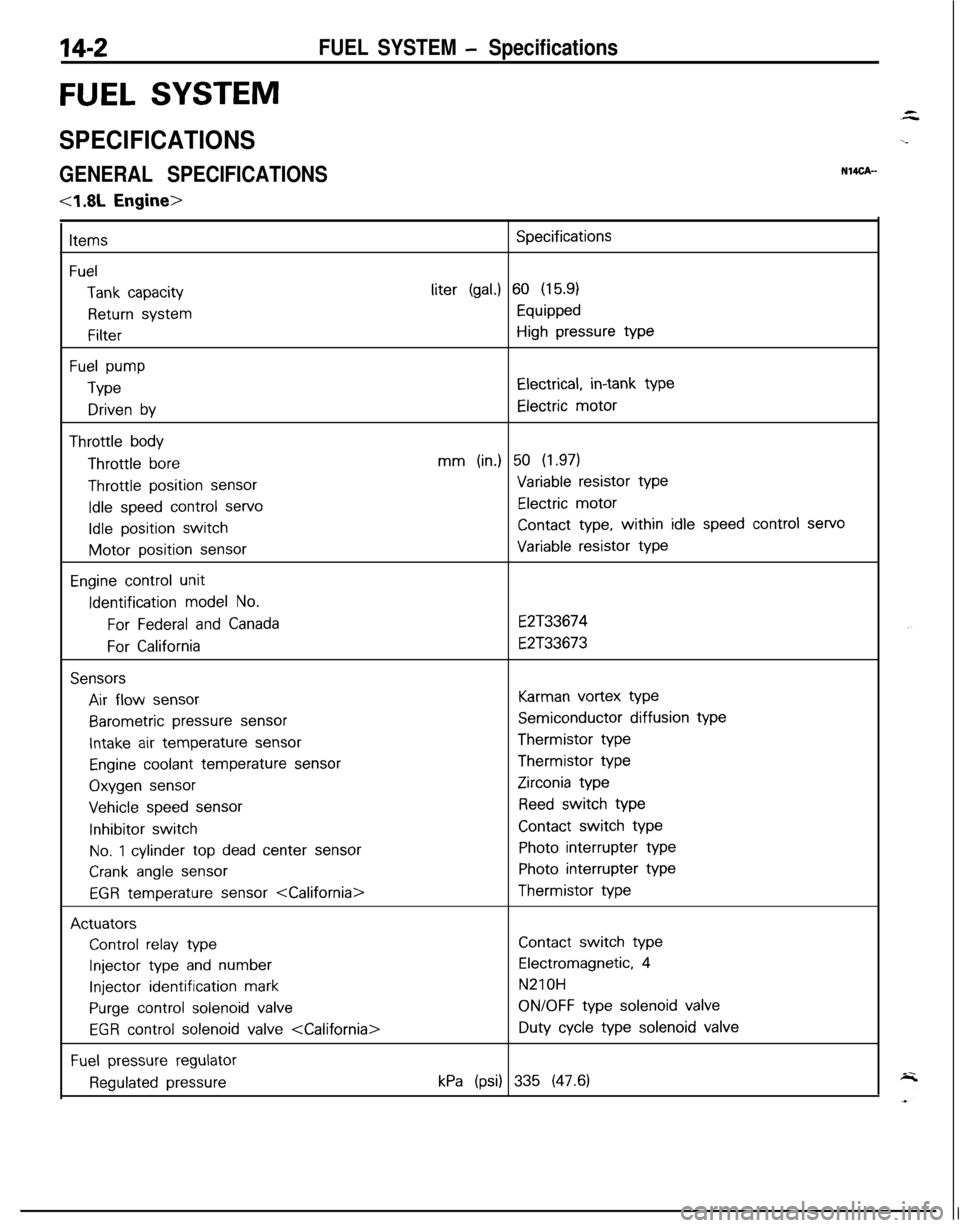
14-2FUEL SYSTEM - Specifications
FUEL SYSTEM
SPECIFICATIONS
GENERAL SPECIFICATIONSNW%-
4.8L Engine>
Items
Fuel
Tank capacity
Return system
Filter
Fuel pump
Type
Driven by
Throttle bodyThrottle
bore
Throttle position sensor
Idle speed control servo
Idle position switchMotor position
sensor
Engine control unitIdentification
model No.
For Federal and Canada
For California
SensorsAir flow
sensor
Barometric pressure sensor
Intake air temperature sensor
Engine coolant temperature sensorOxygen
sensor
Vehicle speed sensorInhibitor switch
No. 1 cylinder top dead center sensor
Crank angle sensor
EGR temperature sensor
Control relay type
Injector type and number
Injector identification mark
Purge control solenoid valve
EGR control solenoid valve
Fuel pressure regulator
Regulated pressure
Specificationsliter
(gal.) 60 (15.9)
Equipped
High pressure type
Electrical, in-tank type
Electric motor
mm (in.) 50 (1.97)
Variable resistor type
Electric motor
Contact type, within idle speed control servo
Variable resistor type
E2T33674
E2T33673
Karman vortex type
Semiconductor diffusion typeThermistor typeThermistor type
Zirconia type
Reed switch type
Contact switch type
Photo interrupter type
Photo interrupter typeThermistor type
Contact switch type
Electromagnetic, 4
N210H
ON/OFF type solenoid valveDuty
cycle type solenoid valve
kPa (psi) 335 (47.6)