fuel type MITSUBISHI ECLIPSE 1991 Service Manual
[x] Cancel search | Manufacturer: MITSUBISHI, Model Year: 1991, Model line: ECLIPSE, Model: MITSUBISHI ECLIPSE 1991Pages: 1216, PDF Size: 67.42 MB
Page 20 of 1216
20INTRODUCTION AND MASTER TROUBLESHOOTING - Towing and Hoisting
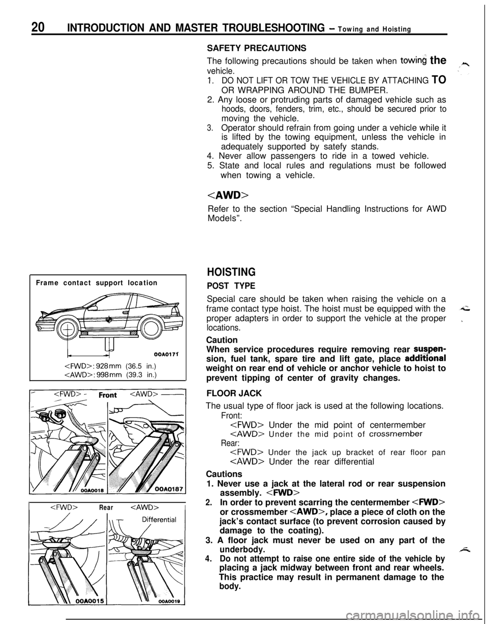
Frame contact support location
OOAOI 71
I
The following precautions should be taken when
towin the
vehicle.
1.DO NOT LIFT OR TOW THE VEHICLE BY ATTACHING TOOR WRAPPING AROUND THE BUMPER.
2. Any loose or protruding parts of damaged vehicle such as
hoods, doors, fenders, trim, etc., should be secured prior tomoving the vehicle.
3.Operator should refrain from going under a vehicle while it
is lifted by the towing equipment, unless the vehicle in
adequately supported by satefy stands.
4. Never allow passengers to ride in a towed vehicle.
5. State and local rules and regulations must be followed
when towing a vehicle.
Refer to the section “Special Handling Instructions for AWD
Models”.
HOISTING
POST TYPESpecial care should be taken when raising the vehicle on a
frame contact type hoist. The hoist must be equipped with the
proper adapters in order to support the vehicle at the proper
locations.Caution
When service procedures require removing rear sutpen-
sion, fuel tank, spare tire and lift gate, place addmonal
weight on rear end of vehicle or anchor vehicle to hoist to
prevent tipping of center of gravity changes.
FLOOR JACK
The usual type of floor jack is used at the following locations.
Front:
Rear:
Cautions
1. Never use a jack at the lateral rod or rear suspension
assembly.
2.In order to prevent scarring the centermember
jack’s contact surface (to prevent corrosion caused by
damage to the coating).
3. A floor jack must never be used on any part of the
underbody.
4.Do not attempt to raise one entire side of the vehicle byplacing a jack midway between front and rear wheels.
This practice may result in permanent damage to the
body.
Page 26 of 1216
26INTRODUCTION AND MASTER TROUBLESHOOTING - :;:%:a=and
Items
Chassis
TireFront suspension
TypeRear suspension
We
Brake
Type
SteeringGear typeFront
RearGear ratio
Fuel tank
Capacityliters (gals.)
1.8L Engine
“Medium”Pl85/70R14
PI 85/70Rl4
Independent
strut
Independentstrut
3l\Fk Torsion&k-k Torsion
Disc
DiscDisc
Disc
Rack and
pinion
03
Rack and
pinion
cn60 (16)
60
(16)
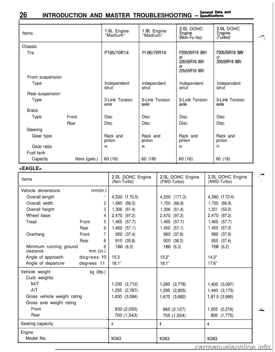
ItemsVehicle dimensions
mm(in.)Overall length
1Overall width
2Overall height
3Wheel base
4
TreadFront5
Rear6
OverhangFront7
Rear8Minimum running ground
9
clearancemm (in.)
Angle of approachdegrees
10Angle of departure
degrees 11
Vehicle weight
kg (Ibs.)Curb weightsMiT
Al-rGross vehicle weight rating
Gross axle weight rating
Front
RearSeating capacity
EngineModel No.
1.8L Engine
“Medium”2.0L DOHC
Kr%n?u rbo)
P205/55Rl6 89H
;;5/55R16 89V%55R16
88V
Independentstrut
zx;;k Torsion
Disc
Disc
Rack and
pinion
co60 (16)
2.0L DOHC
#b”;
P205/55Rl6 89
or
205155R16 88V
Independentstrut
3Lnk Torsion
Disc
Disc
Rack and
pinion
co
60 (16)
2.0L DOHC Engine(Non-Turbo)
4,330(I 70.5)
1,690(66.5)
1,306(51.4)
2,470(97.2)
1,465(57.7)
1,450(57.1)
950(37.4)
910(35.8)
160(6.3)
15.3
18.1”
1,230 (2,712)
1,255 (2,767)
1,630 (3,594)930 (2,050)
700 (1,543)
4
4G63
2.0L DOHC Engine
(FWD-Turbo)
4,350(171.3)
1,700(66.9)
1,306(51.4)
2,470(97.2)
1,465(57.7)
1,450(57.1)
960(37.8)
920(36.2)
160(6.3)
13.2”
18.1”
1,260 (2,778)
1,295 (2,855)
1,670 (3,682)965 (2,127)
705 (1,554)
1
4G63
2.0L DOHC Engine
(AWD-Turbo)
4,380(I 72.4)
1,700(66.9)
1,321(52.0)
2,470(97.2)
1,465(57.7)
1,455(57.3)
960(37.8)
950(37.4)
158(6.2)
14.0”
17.6”
1,405 (3,097)
1,440 (3,175)
I,81 0 (3,990)
1,005 (2,216)
805 (1,775)
4
4G63
Page 27 of 1216
INTRODUCTION AND MASTER TROUBLESHOOTING - f~EEaZ% acld27
=r
9..
Items
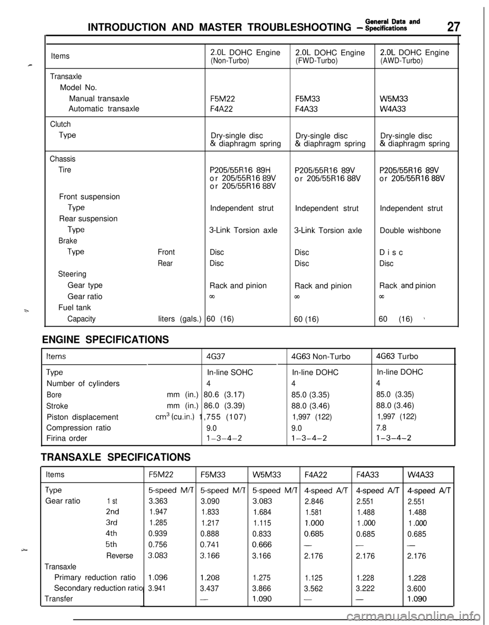
TransaxleModel No.
Manual transaxle
Automatic transaxle
Clutch
Type
Chassis
TireFront suspension
TypeRear suspension
Type
Brake
Type
SteeringGear type
Gear ratio
Fuel tank
Capacity
2.0L DOHC Engine2.0L DOHC Engine2.0L DOHC Engine
(Non-Turbo)(FWD-Turbo)(AWD-Turbo)
F5M22F5M33W5M33
F4A22F4A33W4A33Dry-single disc
Dry-single discDry-single disc& diaphragm spring& diaphragm spring& diaphragm spring
P205/55R16 89HP205155R16 89VP205/55R16 89Vor 205/55R16 89Vor 205/55R16 88Vor 205/55R16 88Vor 205/55R16 88VIndependent strut
Independent strutIndependent strut
3-Link Torsion axle3-Link Torsion axleDouble wishbone
Front
Disc
DiscDisc
RearDisc
DiscDiscRack and pinion
Rack and pinionRack
,and pinion
03coccliters (gals.) 60 (16)
60 (16)60 (16)
)
ENGINE SPECIFICATIONS
Items4G374G63 Non-Turbo4G63 Turbo
TypeIn-line SOHCIn-line DOHCIn-line DOHC
Number of cylinders
444
Boremm (in.) 80.6 (3.17)
85.0 (3.35)85.0 (3.35)
Strokemm (in.) 86.0 (3.39)
88.0 (3.46)88.0 (3.46)
Piston displacement
cm3 (cu.in.) 1,755 (107)1,997 (122)1,997 (122)Compression ratio
9.09.07.8Firina order
1-3-4-21-3-4-21-3-4-2
TRANSAXLE SPECIFICATIONS
ItemsF5M22F5M33W5M33F4A22F4A33W4A33
TypeGear ratio
1 st
2nd
3rd
4th
5th
Reverse
TransaxlePrimary reduction ratio
Secondary reduction
ratio
Transfer
5-speed M/T5-speed M/T
3.363
3.090
1.947
1.833
1.285
1.217
0.939
0.888
0.756
0.741
3.0833.166
5speed M/T4-speed A/T4-speed AIT
3.083
2.8462.551
1.6841.5811.488
1.115
1.0001 .ooo
0.8330.6850.685
0.666--
3.166
2.1762.176
Qspeed AIT
2.551
1.488
1 .ooo
0.685
-
2.176
1.096
3.9411.2081.275
1.1251.2281.228
3.4373.866
3.5623.222
3.600
-1.090--1.090
Page 36 of 1216
o-2LUBRICATION AND MAINTENANCE - General Information
GENERAL INFORMATIONNGQPA--Maintenance and lubrication service recommenda-
tions have been compiled to provide maximum
protection for the vehicle owner’s investment
against all reasonable types of driving conditions.
Since these conditions vary with the individual
vehicle owner’s driving habits, the area in which the
vehicle is operated and the type of driving to which
the vehicle is subjected, it is necessary to prescribe
lubrication and maintenance service on a time
frequency as well as mileage interval basis.
Oils, lubricants and greases are classified and
graded according to standards recommended by theSociety of Automotive Engineers (SAE), the Amer-
ican Petroleum Institute (API) and the National
Lubricating Grease Institute
(NLGI).MAINTENANCE SCHEDULES
Information for service maintenance is provided
under “SCHEDULED MAINTENANCE TABLE”.
Three schedules are provided; one for “Required
Maintenance”, one for “General Maintenance” and
one for “Severe Usage Service”.
Item numbers in the “SCHEDULED MAINTE-
NANCE TABLE” correspond to the item numbers in
the “MAINTENANCE SERVICE” section.
SEVERE SERVICEVehicles operating under severe service conditions
will require more frequent service.
Component service information is included in
appropriate units for vehicles operating under one ormore of the following conditions:
1.Trailer towing or police, taxi, or commercial type
operation2. Operation of Vehicle
(1) Short-trip operation at freezing temperature
(engine not thoroughly warmed up)
(2) More than 50% operation in heavy city
traffic during hot weather above
32°C (90°F)(3) Extensive idling
(4) Driving in sandy areas
(5) Driving in salty areas
(6) Driving in dusty conditions
ENGINE OIL
The SAE grade number indicates the viscosity of
engine oils, for example, SAE 30, which is a single
grade oil. Engine oils are also identified by a dual
number, for example, SAE
lOW-30, which indicates
a multigrade oil.
The API classification system defines oil perform-
ance in terms of engine usage. Only engine oil
designed “For Service SG” or “For Service
SGKD”,when available, should be used. These oils contain
sufficient chemical additives to provide maximum
engine protection. Both the SAE grade and the API
designation can be found on the container.Caution
Test results submitted to EPA have shown thatlaboratory animals develop skin cancer after
prolonged contact with used engine oil. Accor-
dingly, the potential exists for humans
to de-
velop a number of skin disorders, including
cancer, from such exposure to used engine oil.
Care should be’ taken, therefore, when changingengine oil, to minimize the amount and length of
exposure time to used engine
pi! on your skin.
Protective clothing and gloves, that cannot be
penetrated by oil, should be worn. The skin
should be thoroughly washed with soap and
water, or use waterless hand cleaner, to removeany used engine oil. Do not use gasoline,
thinners, or solvents.
GEAR LUBRICANTSThe SAE grade number also indicates the viscosity
of Multi-Purpose Gear Lubricants.
The API classfication system defines gear lubricants
in terms of usage. Typically gear lubricants conform-ing to API
GL-4 or GL-5 with a viscosity of SAE
75W-85W are recommended for manual transaxle.
LUBRICANTS
- GREASES
Semi-solid lubricants, bear the NLGI designation andare further classified as grades 0, 1, 2, 3 etc.
Whenever “Chassis Lubricant” is specified, Multi-
Purpose Grease,
NLGI grade 2 should be used.
MOPAR Multi-Mileage Lubricant, P&t Number
2525035 or equivalent, meets these requirement
and is recommended.
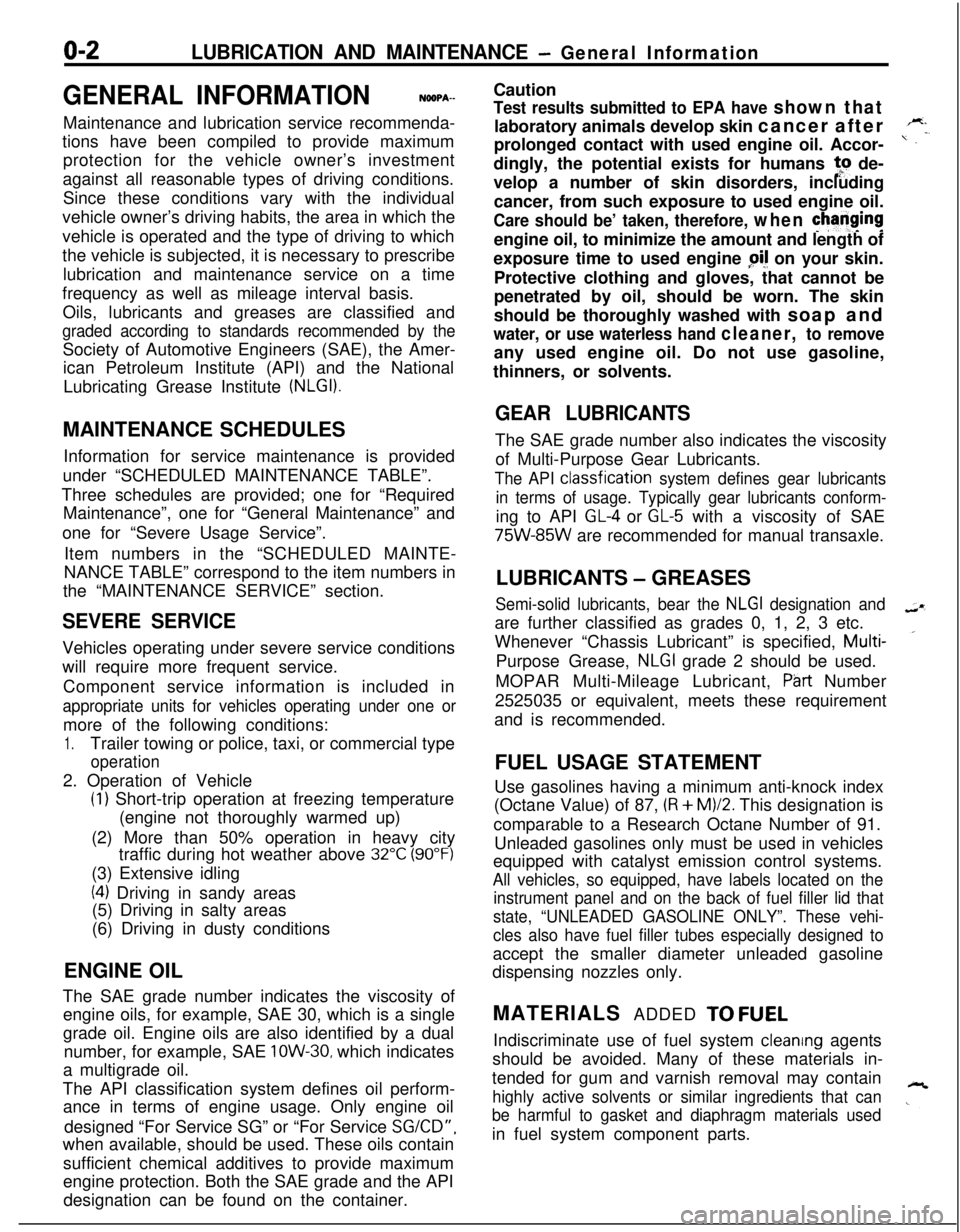
FUEL USAGE STATEMENT
Use gasolines having a minimum anti-knock index
(Octane Value) of 87,
(R + M)/2. This designation is
comparable to a Research Octane Number of 91.
Unleaded gasolines only must be used in vehicles
equipped with catalyst emission control systems.
All vehicles, so equipped, have labels located on the
instrument panel and on the back of fuel filler lid that
state, “UNLEADED GASOLINE ONLY”. These vehi-
cles also have fuel filler tubes especially designed toaccept the smaller diameter unleaded gasoline
dispensing nozzles only.
MATERIALS ADDED
TO FUELIndiscriminate use of fuel system cleanng agents
should be avoided. Many of these materials in-
tended for gum and varnish removal may contain
highly active solvents or similar ingredients that can
be harmful to gasket and diaphragm materials usedin fuel system component parts.
Page 456 of 1216
14-2FUEL SYSTEM - Specifications
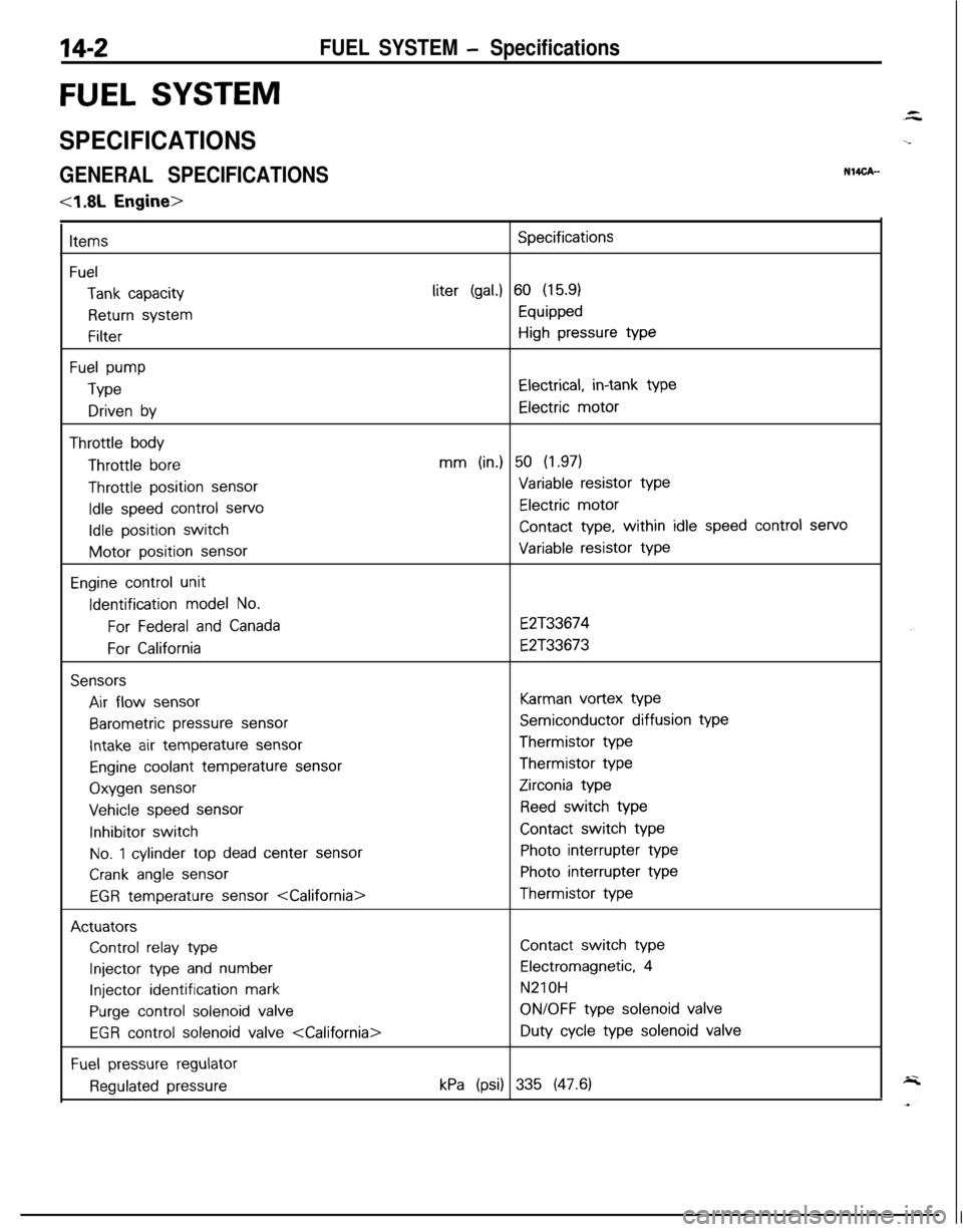
FUEL SYSTEM
SPECIFICATIONS
GENERAL SPECIFICATIONSNW%-
4.8L Engine>
Items
Fuel
Tank capacity
Return system
Filter
Fuel pump
Type
Driven by
Throttle bodyThrottle
bore
Throttle position sensor
Idle speed control servo
Idle position switchMotor position
sensor
Engine control unitIdentification
model No.
For Federal and Canada
For California
SensorsAir flow
sensor
Barometric pressure sensor
Intake air temperature sensor
Engine coolant temperature sensorOxygen
sensor
Vehicle speed sensorInhibitor switch
No. 1 cylinder top dead center sensor
Crank angle sensor
EGR temperature sensor
Control relay type
Injector type and number
Injector identification mark
Purge control solenoid valve
EGR control solenoid valve
Fuel pressure regulator
Regulated pressure
Specificationsliter
(gal.) 60 (15.9)
Equipped
High pressure type
Electrical, in-tank type
Electric motor
mm (in.) 50 (1.97)
Variable resistor type
Electric motor
Contact type, within idle speed control servo
Variable resistor type
E2T33674
E2T33673
Karman vortex type
Semiconductor diffusion typeThermistor typeThermistor type
Zirconia type
Reed switch type
Contact switch type
Photo interrupter type
Photo interrupter typeThermistor type
Contact switch type
Electromagnetic, 4
N210H
ON/OFF type solenoid valveDuty
cycle type solenoid valve
kPa (psi) 335 (47.6)
Page 457 of 1216
FUEL SYSTEM - Specifications14-3
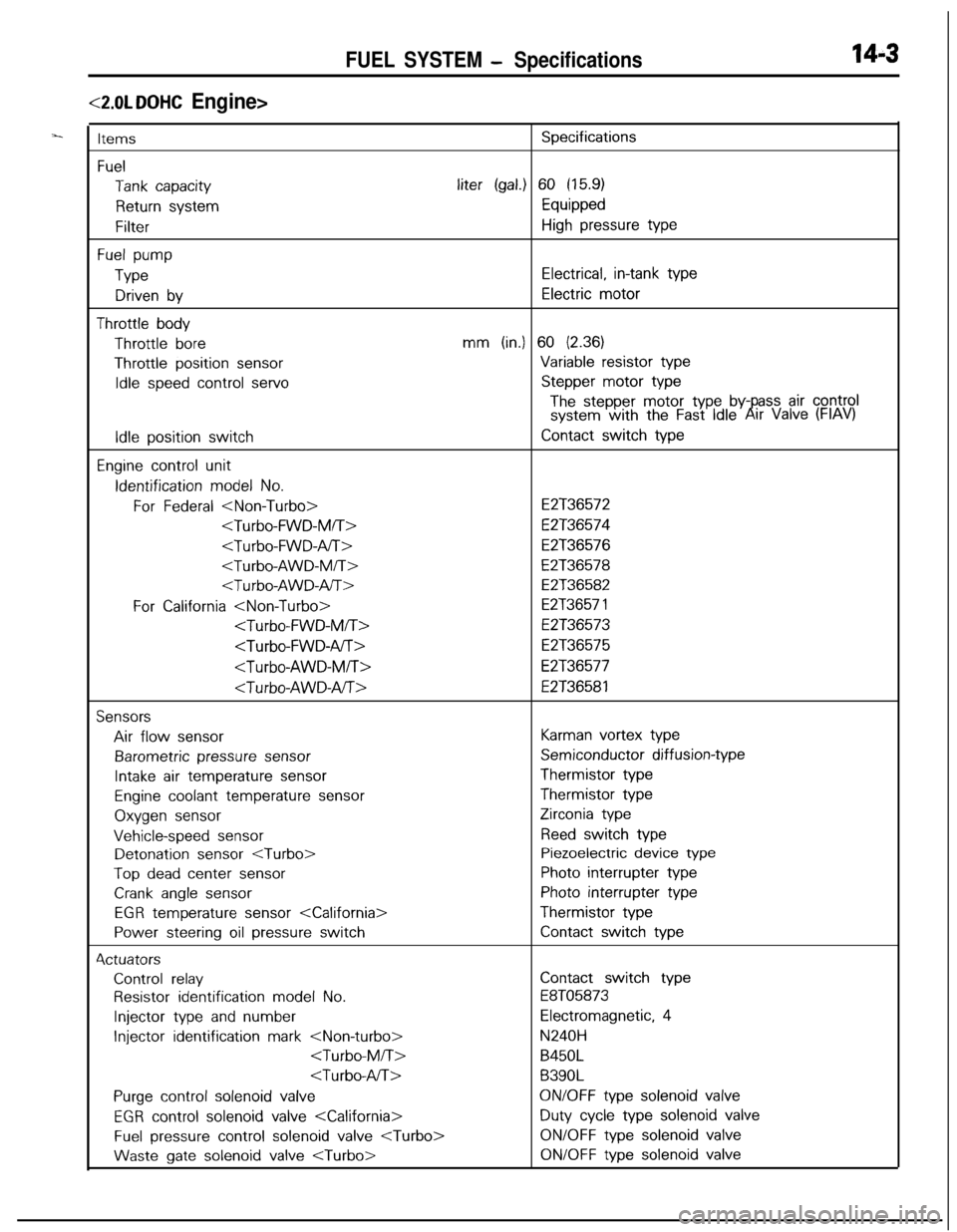
<2.0L DOHC Engine>
ItemsSpecifications
Fuel
Tank capacityliter (gal.) 60 (15.9)
Return systemEquipped
FilterHigh pressure type
Fuel pump
TypeElectrical, in-tank type
Driven byElectric motor
Throttle bodyThrottle
boremm (in.) 60 (2.36)Throttle position
sensorVariable resistor type
Idle speed control servoStepper motor type
The stepper motor type by- ass air controlsystem with the Fast Idle6!rr Valve (FIAV)
Idle position switchContact switch type
Engine control unitIdentification
model No.
For Federal
E2T36574
E2T36576
E2T36578
E2T36582
For California
E2T36573
E2T36575
E2T36577
E2T36581
SensorsAir flow
sensorKarman vortex type
Barometric pressure sensorSemiconductor diffusion-type
Intake air temperature sensorThermistor type
Engine coolant temperature sensorThermistor type
Oxygen sensorZirconia type
Vehicle-speed sensorReed switch typeDetonation
sensor
Top dead center sensorPhoto interrupter type
Crank angle sensorPhoto interrupter type
EGR temperature sensor
Power steering oil pressure switchContact switch type4ctuators
Control relayContact switch type
Resistor identification model No.E8T05873
Injector type and numberElectromagnetic, 4
Injector identification mark
B450L
B390L
Purge control solenoid valveON/OFF type solenoid valve
EGR control solenoid valve
Fuel pressure control solenoid valve
gate solenoid valve
Page 517 of 1216
FUEL SYSTEM - MPI Svstem Inspection <1.8L Engine>18-63
Throttle position sensor
Groundoutput
Sensorpower
SUPPlY(5V)
1 FUO507
6FU1244Motor
Dosition sensor connector
(motor ‘side, front view)
T
6FU1247Motor position sensor
connector(motor side, front view)
6FU1252
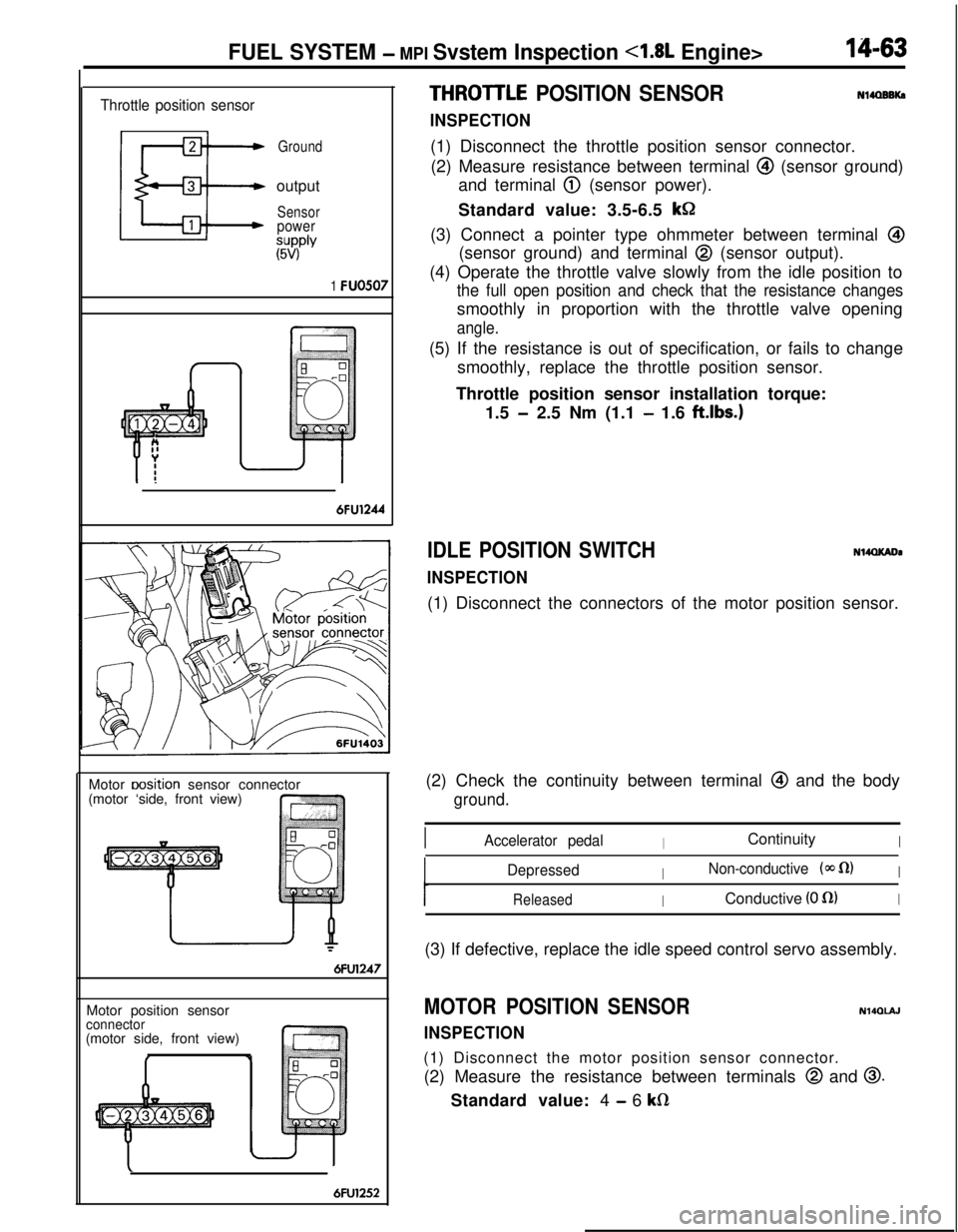
THROITLE POSITION SENSOR
INSPECTION
Nl4OBBKa(1) Disconnect the throttle position sensor connector.
(2) Measure resistance between terminal
@I (sensor ground)
and terminal
@ (sensor power).
Standard value: 3.5-6.5
kGI(3) Connect a pointer type ohmmeter between terminal
@(sensor ground) and terminal
@ (sensor output).
(4) Operate the throttle valve slowly from the idle position to
the full open position and check that the resistance changessmoothly in proportion with the throttle valve opening
angle.(5) If the resistance is out of specification, or fails to change
smoothly, replace the throttle position sensor.
Throttle position sensor installation torque:
1.5
- 2.5 Nm (1.1 - 1.6 ftlbs.)
IDLE POSITION SWITCH
INSPECTION
N14QKADa(1) Disconnect the connectors of the motor position sensor.
(2) Check the continuity between terminal
@ and the body
ground.
IAccelerator pedalIContinuityI
DepressedINon-conductive (@J fl)I
ReleasedIConductive (0 fl)I(3) If defective, replace the idle speed control servo assembly.
MOTOR POSITION SENSOR
INSPECTION
N140lAJ(1) Disconnect the motor position sensor connector.
(2) Measure the resistance between terminals
@ and 0.Standard value: 4
- 6 kfi
Page 531 of 1216
FUEL SYSTEM - MPI Svstem InsDection <2.0L DOHC Engine>14-77INSTALLATION
(1) Apply specified sealant to threaded portion and tighten to
specified torque.
Specified sealant: MOPAR Part No.4318034 or
equivalent
Specified torque: 20
- 40 Nm (15 - 29 ft.lbs.1(2) Fasten harness connectors securely.
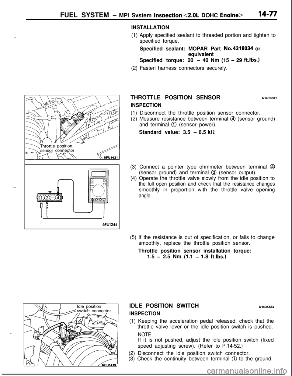
THROTTLE POSITION SENSOR
INSPECTION
N14QBBKl(1) Disconnect the throttle position sensor connector.
(2) Measure resistance between terminal
@I (sensor ground)
and terminal
@ (sensor power).
Standard value: 3.5
- 6.5 kR(3) Connect a pointer type ohmmeter between terminal
@I(sensor ground) and terminal
@ (sensor output).
(4) Operate the throttle valve slowly from the idle position to
the full open position and check that the resistance changessmoothly in proportion with the throttle valve opening
angle.
6FU1244(5) If the resistance is out of specification, or fails to change
smoothly, replace the throttle position sensor.
Throttle position sensor installation torque:
1.5
- 2.5 Nm (1.1 - 1.8 ft.lbs.)
J II\/ hFU1419IDLE POSITION SWITCH
INSPECTION
N14QKAEa(1) Keeping the acceleration pedal released, check that the
throttle valve lever or the idle position switch is pushed.
NOTEIf it is not pushed, adjust the idle position switch (fixed
speed adjusting screw). (Refer to
P.14-52.)(2) Disconnect the idle position switch connector.
(3) Check the continuity between terminal
@) to the ground.
Page 548 of 1216
14-94FUEL SYSTEM - Fuel Tank
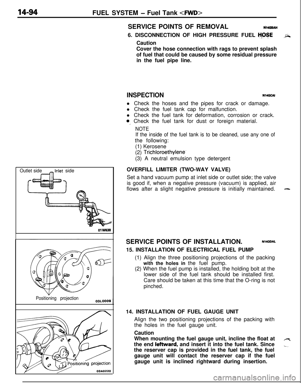
Outlet side_ Inlet side01
W838
Positioning projection
03A0220SERVICE POINTS OF REMOVALtilirro8AH
6. DISCONNECTION OF HIGH PRESSURE FUEL
H;OSECaution
Cover the hose connection with rags to prevent splash
of fuel that could be caused by some residual pressure
in the fuel pipe line.
INSPECTIONN14GCAll Check the hoses and the pipes for crack or damage.
l Check the fuel tank cap for malfunction.
l Check the fuel tank for deformation, corrosion or crack.
0,. Check the fuel tank for dust or foreign material.
NOTE
If the inside of the fuel tank is to be cleaned, use any one ofthe following:
(1) Kerosene
(2)
Trichloroethylene-(3) A neutral emulsion type detergent
OVERFILL LIMITER (TWO-WAY VALVE)
Set a hand vacuum pump at inlet side or outlet side; the valve
is good if, when a negative pressure (vacuum) is applied, air
flows after a slight negative pressure is initially maintained.
SERVICE POINTS OF INSTALLATION.
Nl4DDAL15. INSTALLATION OF ELECTRICAL FUEL PUMP
(1) Align the three positioning projections of the packing
with the holes in the fuel pump.
(2) When the fuel pump is installed, the holding bolt at the
lower side of the fuel tank should be installed first.
Care should be taken at this time that the O-ring is not
pinched.14. INSTALLATION OF FUEL GAUGE UNIT
Align the two positioning projections of the packing with
the holes in the fuel gauge unit.
Caution
When mounting the fuel gauge unit, incline the float at
the end leftward, and insert it into the fuel tank. Since
the reserver cap is provided in the fuel tank, the fuel
gauge unit will contact the reserver cap if the fuel
gauge unit is inclined rightward during insertion.
-
4
-,
Page 552 of 1216
14-98FUEL SYSTEM -Fuel Tank
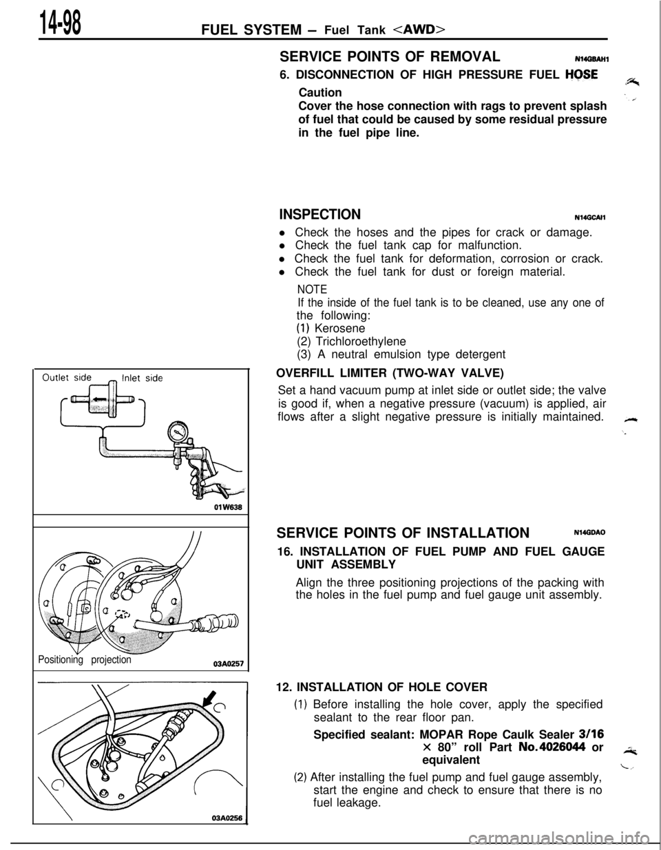
W636
Positioning projection03AO257
\03A0256SERVICE POINTS OF REMOVAL
N14G6AHl6. DISCONNECTION OF HIGH PRESSURE FUEL
HGSECaution
Cover the hose connection with rags to prevent splash
of fuel that could be caused by some residual pressure
in the fuel pipe line.
INSPECTIONN14GCAHl Check the hoses and the pipes for crack or damage.
l Check the fuel tank cap for malfunction.
l Check the fuel tank for deformation, corrosion or crack.
l Check the fuel tank for dust or foreign material.
NOTE
If the inside of the fuel tank is to be cleaned, use any one ofthe following:
(1) Kerosene
(2) Trichloroethylene
(3) A neutral emulsion type detergent
OVERFILL LIMITER (TWO-WAY VALVE)
Set a hand vacuum pump at inlet side or outlet side; the valve
is good if, when a negative pressure (vacuum) is applied, air
flows after a slight negative pressure is initially maintained.
SERVICE POINTS OF INSTALLATION
N14GDAO16. INSTALLATION OF FUEL PUMP AND FUEL GAUGE
UNIT ASSEMBLY
Align the three positioning projections of the packing with
the holes in the fuel pump and fuel gauge unit assembly.
12. INSTALLATION OF HOLE COVER
) Before installing the hole cover, apply the specified
sealant to the rear floor pan.
Specified sealant: MOPAR Rope Caulk Sealer
3116
x 80” roll Part No.4026044 or
equivalent
!) After installing the fuel pump and fuel gauge assembly,
start the engine and check to ensure that there is no
fuel leakage.