engine oil MITSUBISHI ECLIPSE 1991 Owner's Guide
[x] Cancel search | Manufacturer: MITSUBISHI, Model Year: 1991, Model line: ECLIPSE, Model: MITSUBISHI ECLIPSE 1991Pages: 1216, PDF Size: 67.42 MB
Page 281 of 1216
COOLING- Water Hose and Water Pipe <2.0L DOHC Engine (Turbo)>7-330140552
Mating marks
04A0090
rMating marks
04A0090
SERVICE POINTS OF REMOVALNO7lBAC311. DISCONNECTION OF POWER STEERING OIL PUMP
Disconnect the oil pump with hoses from the bracket.
NOTEThe removed power steering oil pump should be fastened
(by using rope, etc.) in a position that will not interfere with
the removal/installation of the engine assembly.
27. REMOVAL OF TURBOCHARGER ASSEMBLY
Remove the turbocharger assembly with the exhaust
fitting, water pipe A, water pipe
B and the oil pipe attached
to it.
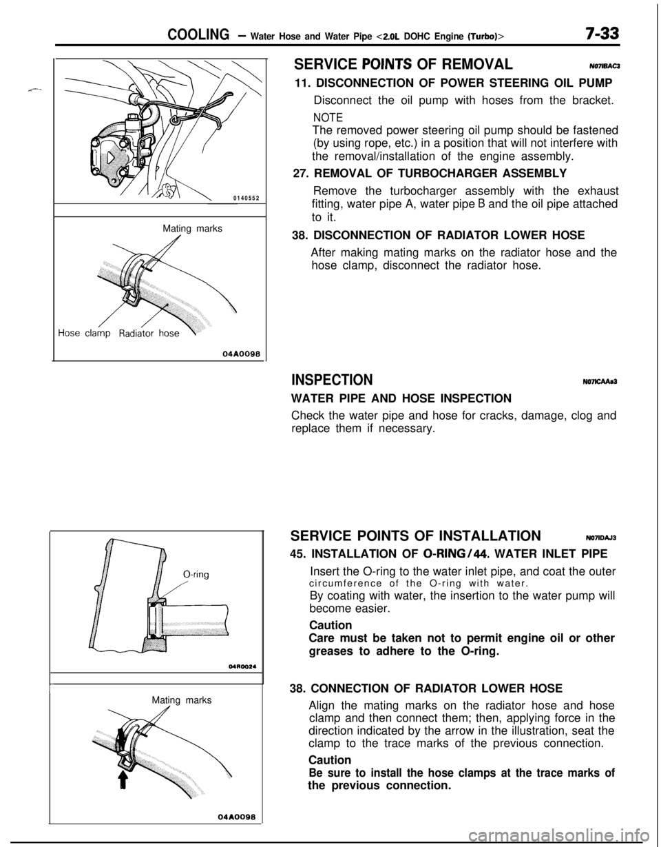
38. DISCONNECTION OF RADIATOR LOWER HOSE
After making mating marks on the radiator hose and the
hose clamp, disconnect the radiator hose.
INSPECTIONN07lCAAa3WATER PIPE AND HOSE INSPECTION
Check the water pipe and hose for cracks, damage, clog and
replace them if necessary.
SERVICE POINTS OF INSTALLATION
N071DAJ345. INSTALLATION OF
0-RING/44. WATER INLET PIPE
Insert the O-ring to the water inlet pipe, and coat the outer
circumference of the O-ring with water.
By coating with water, the insertion to the water pump will
become easier.
Caution
Care must be taken not to permit engine oil or other
greases to adhere to the O-ring.
38. CONNECTION OF RADIATOR LOWER HOSE
Align the mating marks on the radiator hose and hose
clamp and then connect them; then, applying force in the
direction indicated by the arrow in the illustration, seat the
clamp to the trace marks of the previous connection.
Caution
Be sure to install the hose clamps at the trace marks ofthe previous connection.
Page 282 of 1216
7-34 COOLINGWater Hose and Water Pipe <2.0L DOHC Engine (Turbo)>/Engine Coolant Temperature- Gauge Unit. Engine Coolant Temoerature Sensor and Enoine Coolant Temoerature Switch
05A0026
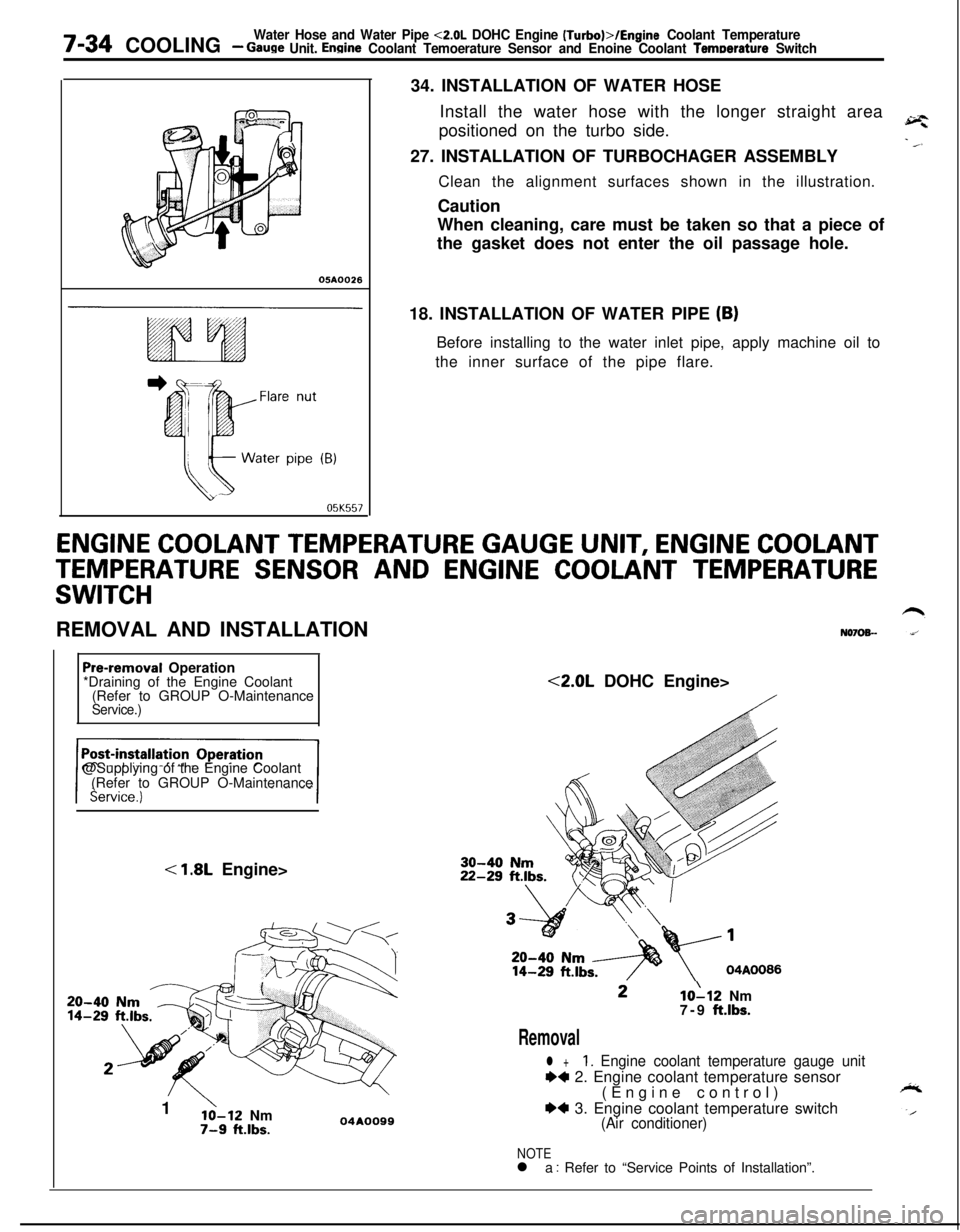
05K55734. INSTALLATION OF WATER HOSE
Install the water hose with the longer straight area
positioned on the turbo side.
27. INSTALLATION OF TURBOCHAGER ASSEMBLY
Clean the alignment surfaces shown in the illustration.
Caution
When cleaning, care must be taken so that a piece of
the gasket does not enter the oil passage hole.
18. INSTALLATION OF WATER PIPE
(B)Before installing to the water inlet pipe, apply machine oil to
the inner surface of the pipe flare.
ENGINE COOLANT TEMPERATURE GAUGE UNIT, ENGINE COOLANT
TEMPERATURE SENSOR AND ENGINE COOLANT TEMPERATURE
SWITCHREMOVAL AND INSTALLATION
N070%-
Pre-removal Operation
*Draining of the Engine Coolant
(Refer to GROUP O-Maintenance
Service.)@Supplying of the Engine Coolant
(Refer to GROUP O-Maintenance
< 1.8L Engine>
20-4014-291
’lo-12 Nm7-9 ft.lbs.04AOO99<2.0L DOHC Engine>10112 Nm
7-9 ft.lbs.
Removal
l +1. Engine coolant temperature gauge unit
++ 2. Engine coolant temperature sensor
(Engine control)
*4 3. Engine coolant temperature switch(Air conditioner)
NOTEl a : Refer to “Service Points of Installation”.
Page 283 of 1216
COOLINGEngine Coolant Temperature Gauge Unit, Engine Coolant- TemDerature Sensor and Enaine Coolant Temperature Switch7-35
.---
Sensor04GO033
0400032
1c0010
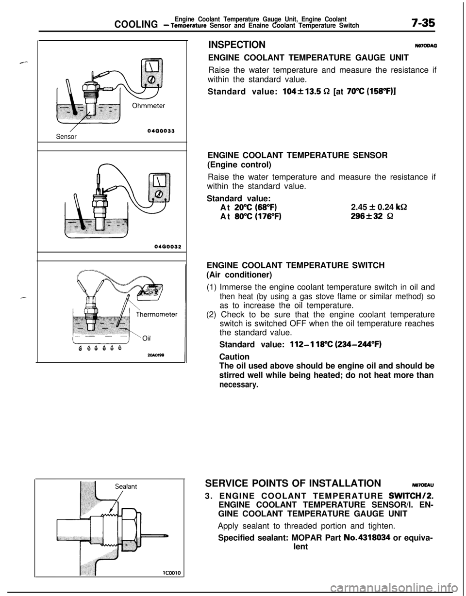
INSPECTIONNomDM3ENGINE COOLANT TEMPERATURE GAUGE UNIT
Raise the water temperature and measure the resistance if
within the standard value.
Standard value:
104213.5 52 [at 70°C (158OF)lENGINE COOLANT TEMPERATURE SENSOR
(Engine control)
Raise the water temperature and measure the resistance if
within the standard value.
Standard value:
At
20°C (68°F)2.45 + 0.24 k&
At
80°C (176°F)296f32 8ENGINE COOLANT TEMPERATURE SWITCH
(Air conditioner)
(1) Immerse the engine coolant temperature switch in oil and
then heat (by using a gas stove flame or similar method) soas to increase the oil temperature.
(2) Check to be sure that the engine coolant temperature
switch is switched OFF when the oil temperature reaches
the standard value.
Standard value:
112-l 18°C (234-244°F)Caution
The oil used above should be engine oil and should be
stirred well while being heated; do not heat more than
necessary.SERVICE POINTS OF INSTALLATION
NO7OEAU3. ENGINE COOLANT TEMPERATURE
SWITCHI2.ENGINE COOLANT TEMPERATURE SENSOR/l. EN-
GINE COOLANT TEMPERATURE GAUGE UNIT
Apply sealant to threaded portion and tighten.
Specified sealant: MOPAR Part No.4318034 or equiva-
lent
Page 285 of 1216
9-1
ENGINE
CONTENTSNOSAA-
ENGINE<1.8L
Engine>..................
24CRANKSHAFT, FLYWHEEL AND
DRIVE PLATE................................................
69
CYLINDER
BLOCK.........................................72
CYLINDERHEADANDVALVE
...................
53CYLINDER HEAD GASKET
...........................
36ENGINE ASSEMBLY
.....................................31ENGINE MOUNTING
....................................
28ENGINE ROLL STOPPER
.............................
30FRONT CASE, OIL PUMP AND
SILENT SHAFT
..............................................
58
OILPANANDOILSCREEN........................34
PISTON AND CONNECTING ROD
..............
65ROCKER ARMS AND ROCKER SHAFTS..
..51ROCKER ARMS, ROCKER ARM SHAFTS
AND CAMSHAFT
..........................................48
SERVICE ADJUSTMENT PROCEDURES..
...24TIMING BELT
................................................41TRANSAXLE MOUNTING
............................
29
ENGINE <2.0L DOHC Engine> . . . . . .
74CAMSHAFTS AND CAMSHAFT
OIL SEALS
. . . . . . . . . . . . . . . . . . . . . . . . . . . . . . . . . . . . . . . . . . . . . . . . . . . . .84CAMSHAFTAND
ROCKERARM. . . . . . . . . . . . . . . .109CRANKSHAFT, FLYWHEEL AND
DRIVE PLATE. . . . . . . . . . . . . . . . . . . . . . . . . . . . . . . . . . . . . . . . . . . . . . . .132
CYLINDERBLOCK. . . . . . . . . . . . . . . . . . . . . . . . . . . . . . . . . . . . . . . . .136
CYLINDERHEADANDVALVE
. . . . . . . . . . . . . . . . . . .112CYLINDER HEAD GASKET
...........................90ENGINE ASSEMBLY
.......................................81ENGINE MOUNTING
......................................77ENGINE ROLL STOPPER
...............................
79FRONT CASE, OIL PUMP AND
SILENT SHAFT
..............................................117OIL PAN AND OIL SCREEN
..........................
87
PISTONANDCONNECTING
ROD..............127SERVICE ADJUSTMENT PROCEDURES..
.....76TIMING BELT
................................................
85TRANSAXLE MOUNTING
............................78
GENERALINFORMATION................2
SPECIAL TOOLS...............................20
SPECIFICATIONS...............................8General Specifications
................................8Sealants and Adhesives
.............................19Service Specifications
.................................8Torque Specifications
.................................18
TROUBLESHOOTING........................23Compression Too Low
Connecting Rod Noise/Main Bearing Noise
Excessive Engine Rolling and Vibration
Noisy Valves
Oil Pressure Drop
Oil Pressure Too High
Timing Belt Noise
Page 288 of 1216
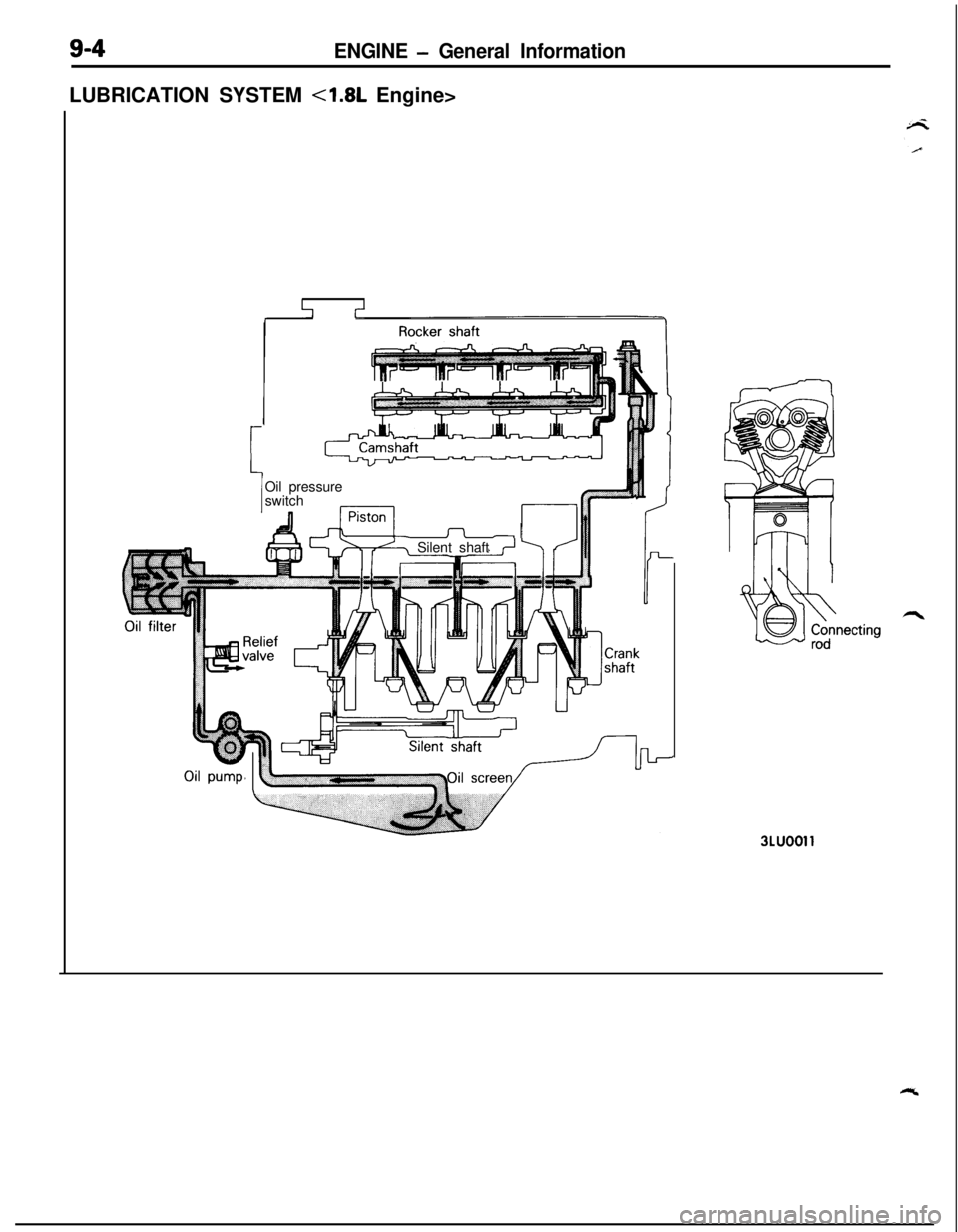
ENGINE - General InformationLUBRICATION SYSTEM <1.8L Engine>
r
A-1Oil pressure
switchIIISilent shaft
3LUOOll
Page 291 of 1216
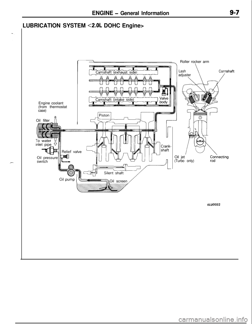
ENGINE - General Information9-7
LUBRICATION SYSTEM <2.0L DOHC Engine>Engine coolant
(from thermostat
case)a
Oil filterRoller rocker arm
LashadjusterCan
/
ILt
K
63
ishaftOil jet
(Turbo only)
Oil pump I y+Oilscreen /6LUOO52
Page 293 of 1216
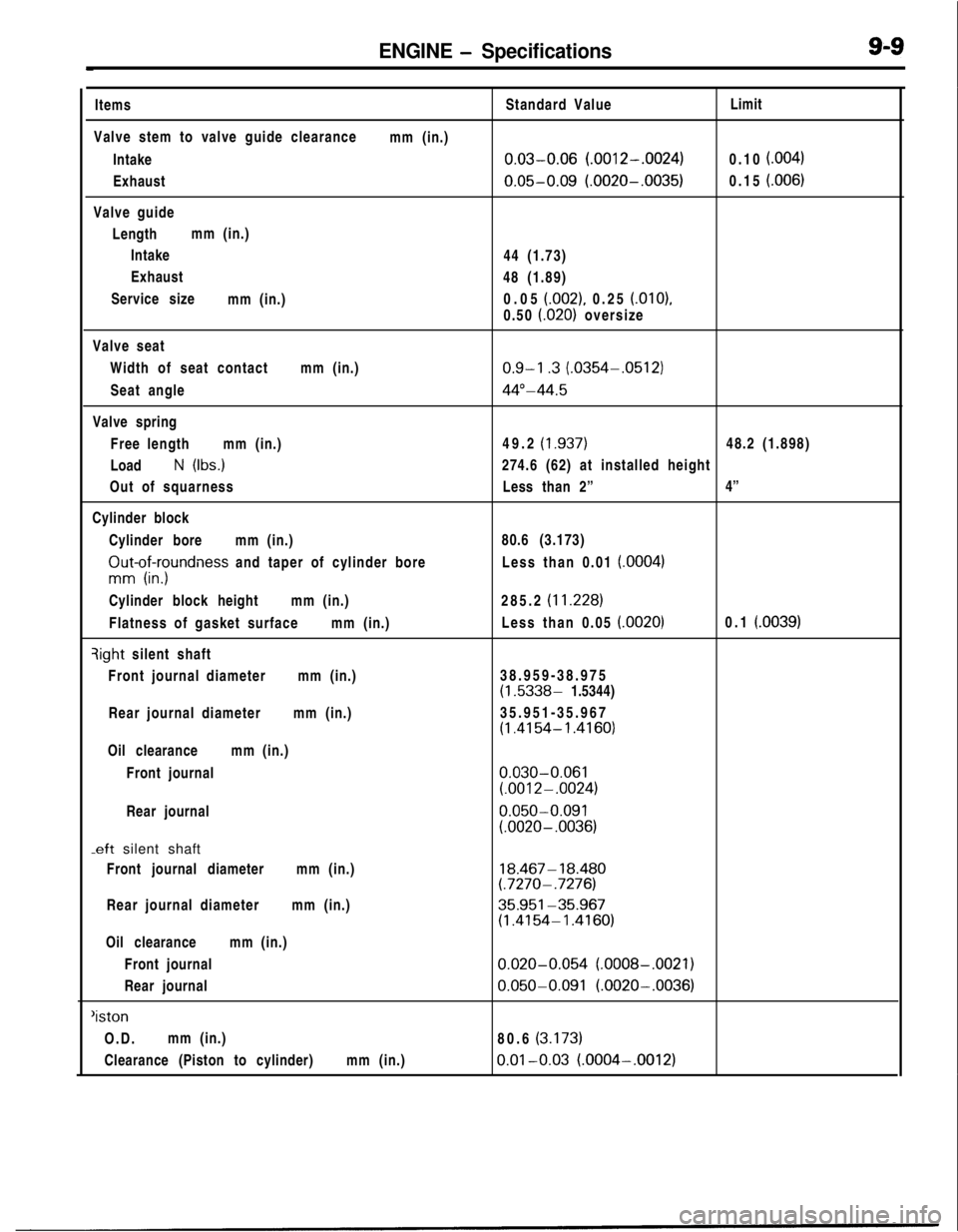
ENGINE - SpecificationsItems
Valve stem to valve guide clearance
Intake
Exhaust
Valve guide
Lengthmm (in.)
Intake
Exhaust
Service size
mm (in.)mm (in.)Standard Value
0.03-0.06 (.0012-.0024)
0.05-0.09 (.0020-.0035)44 (1.73)
48 (1.89)
0.05
(.002), 0.25 (.OlO),
0.50
i.020) oversizeLimit
0.10
f.004)0.15
i.006)Valve seat
Width of seat contactmm (in.)
Seat angle
Valve spring
Free lengthmm (in.)
Load
N (Ibs.)
Out of squarness
Cylinder block
Cylinder boremm (in.)
ZIut-of;yundness and taper of cylinder bore
Cylinder block heightmm (in.)
Flatness of gasket surfacemm (in.)qight silent shaft
Front journal diametermm (in.)
Rear journal diametermm (in.)
Oil clearancemm (in.)
Front journal
Rear journal
-eft silent shaft
Front journal diametermm (in.)
Rear journal diametermm (in.)
Oil clearancemm (in.)
Front journal
Rear journal
‘istonO.D.mm (in.)
Clearance (Piston to cylinder)mm (in.)
0.9-l .3 (.0354-.0512)
44”-44.549.2
(1.937)48.2 (1.898)
274.6 (62) at installed height
Less than 2”4”
80.6 (3.173)
Less than 0.01
(.0004)285.2
(11.228)Less than 0.05
(.0020)0.1 (.0039)38.959-38.975
(1.5338- 1.5344)
35.951-35.967
(1.4154- 1.4160)
0.030-0.061(.0012-.0024)
0.050-0.091(.0020- .0036)
18.467- 18.480(.7270- .7276)
35.951-35.967(1.4154-1.4160)
0.020-0.054 (.0008-.0021)
0.050-0.091 (.0020-.0036)80.6
(3.173)
0.01-0.03 (.0004-.0012)
Page 294 of 1216
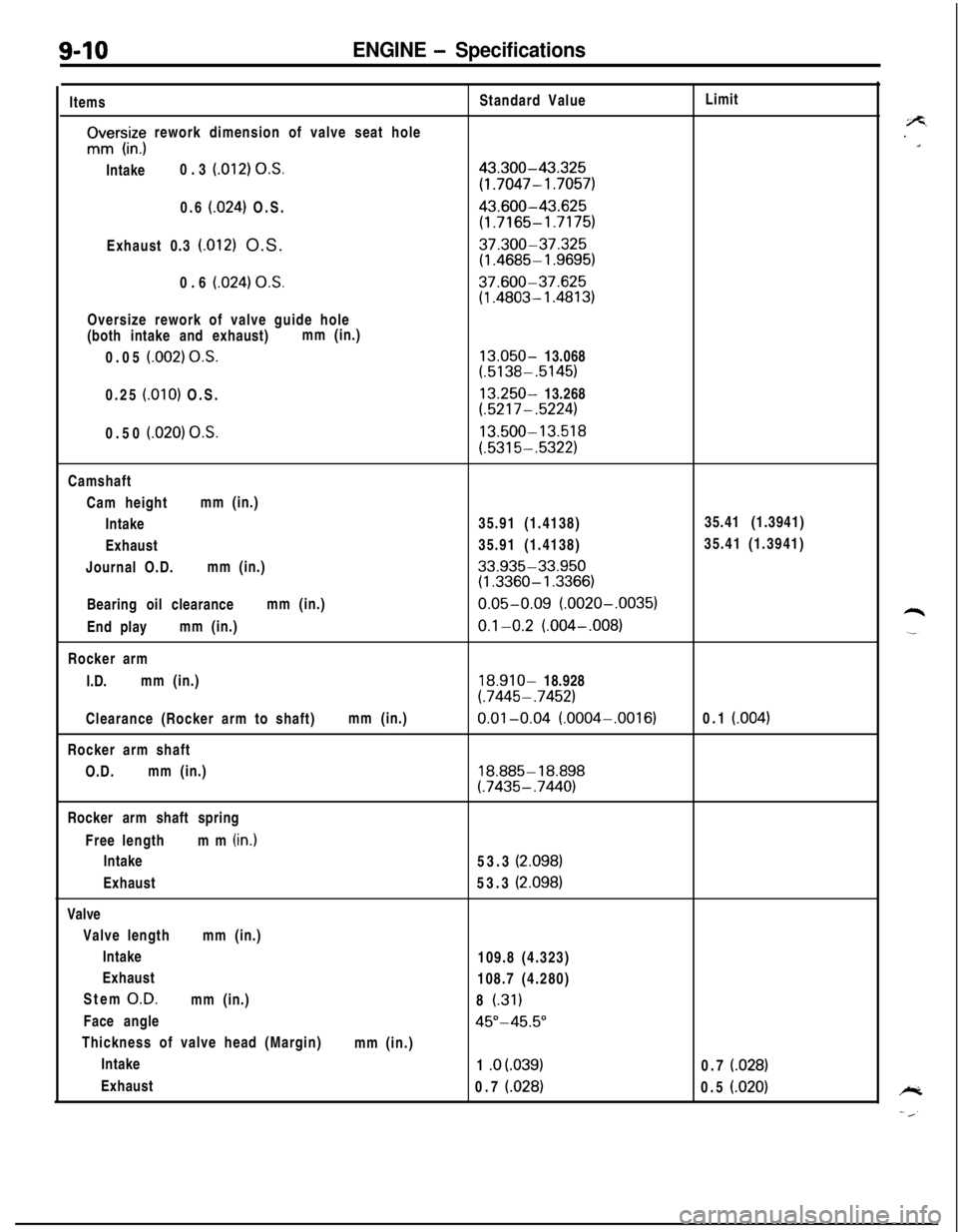
9-10ENGINE - SpecificationsItems
rIvrs,iz; rework dimension of valve seat hole
Intake0.3
(012) O.S.0.6
(024) O.S.
Exhaust 0.3
(.012) O.S.
0.6
(024) OS.Oversize rework of valve guide hole
(both intake and exhaust)mm (in.)
0.05
(.002) O.S.0.25
(.OlO) O.S.
0.50
(.020) O.S.Standard Value
43.300-43.325
(1.7047- 1.7057)
43.600-43.625
(1.7165-1.7175)
37.300-37.325(1.4685- 1.9695)
37.600-37.625(1.4803- 1.4813)
13.050- 13.068(.5138-.5145)
13.250- 13.268(.5217-.5224)
13.500-13.518
(.5315-.5322)Limit
Camshaft
Cam heightmm (in.)
Intake35.91 (1.4138)35.41 (1.3941)
Exhaust35.91 (1.4138)35.41 (1.3941)
Journal O.D.mm (in.)
33.935-33.950(1.3360- 1.3366)Bearing oil clearancemm (in.)
0.05-0.09 (.0020-.0035)End playmm (in.)
0.1-0.2 (.004-,008)Rocker arm
I.D.mm (in.)
18.910- 18.928
(.7445- .7452)Clearance (Rocker arm to shaft)mm (in.)
0.01-0.04 (.0004-.0016)0.1 (004)Rocker arm shaft
O.D.mm (in.)
18.885- 18.898(.7435-.7440)Rocker arm shaft spring
Free lengthmm (in.)
Intake
Exhaust
Valve
Valve lengthmm (in.)
Intake
Exhaust
Stem
O.D.mm (in.)
Face angle
Thickness of valve head (Margin)
Intake
Exhaust53.3
(2.098)53.3
(2.098)109.8 (4.323)
108.7 (4.280)
8
(.31)
45”-45.5”mm (in.)
1 .o
(.039)0.7 (028)0.7
(.028)0.5 (.020)
Page 295 of 1216
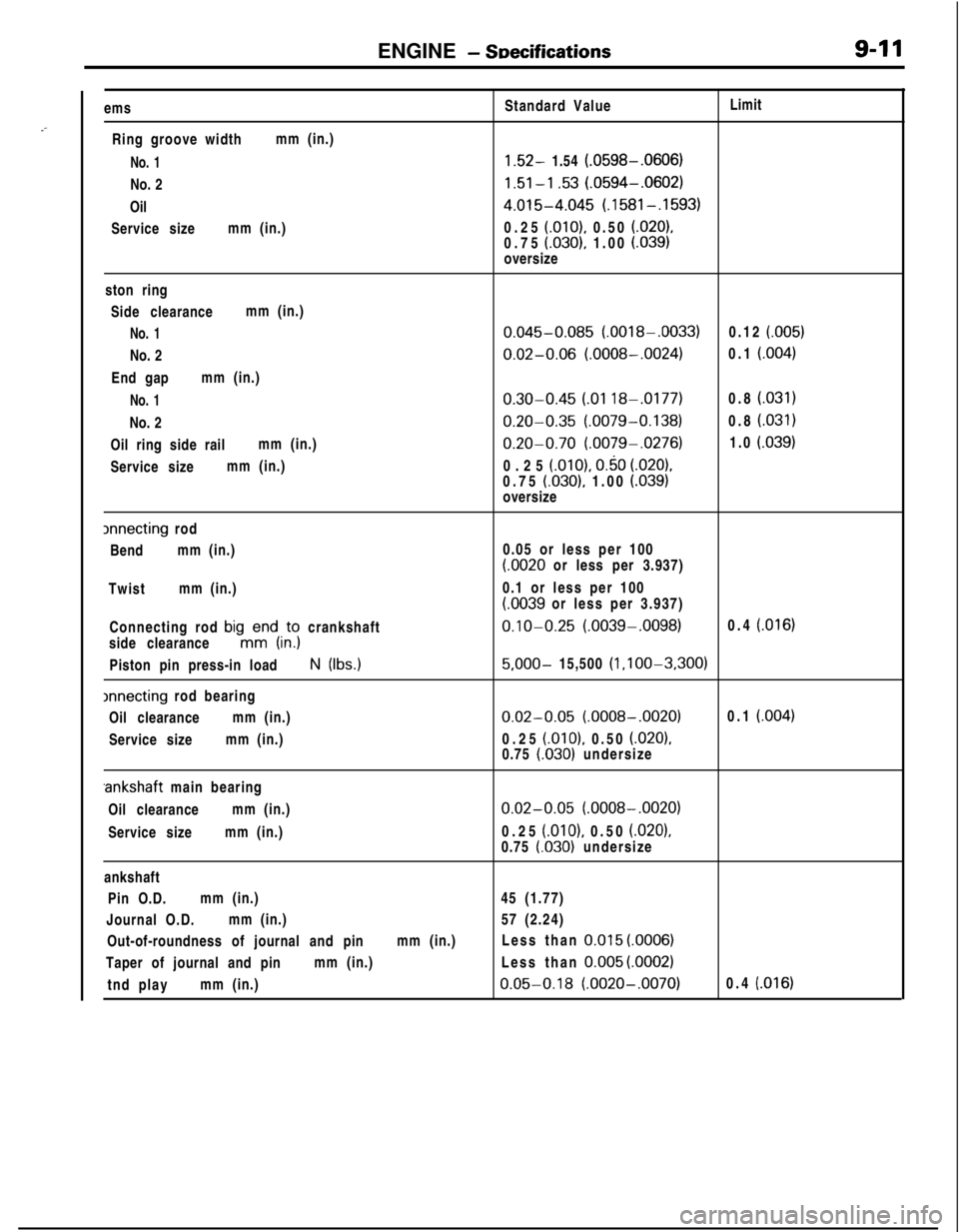
ENGINE - SDecifications9-11
.-ems
Ring groove widthmm (in.)
No. 1No. 2
Oil
Service sizemm (in.)Standard ValueLimit1.52- 1.54 (.0598-.0606)
1.51-l .53 (.0594-.0602)
4.015-4.045 (.1581-.1593)0.25
(.OlO), 0.50 (.020),0.75 (.030), 1.00 (.039)oversize
ston ring
Side clearancemm (in.)
No. 1No. 2
End gapmm (in.)
No. 1No. 2
Oil ring side railmm (in.)
Service sizemm (in.)
0.045-0.085 (.0018-.0033)0.12 (.005)
0.02-0.06 (.0008-.0024)0.1 (.004)
0.30-0.45 LO1 188.0177)0.8 (.031)
0.20-0.35 (.0079-0.138)0.8 i.031)
0.20-0.70 (.0079-.0276)1.0 (.039)0.25
(.OlO), 0.50 (.020).0.75 (.030), 1.00 LO391oversize
lnnecting rod
Bendmm (in.)
Twistmm (in.)
Connecting rod
bigmKdi,;; crankshaft
side clearance
Piston pin press-in loadN (Ibs.)
xrnecting rod bearing
Oil clearancemm (in.)
Service sizemm (in.)0.05 or less per 100
(.0020 or less per 3.937)
0.1 or less per 100
LOO39 or less per 3.937)
0.10-0.25 (.0039-.0098)0.4 (.016)
5,000- 15,500 (l ,l OO-3,300)
0.02-0.05 (.0008-.0020)0.1 (.004)0.25
(.OlO), 0.50 (.020),0.75 (.030) undersize.ankshaft main bearing
Oil clearancemm (in.)
Service sizemm (in.)
0.02-0.05 (.0008-.0020)0.25
(.OlO), 0.50 i.0201,
0.75 l.030) undersize
ankshaft
Pin O.D.mm (in.)45 (1.77)
Journal O.D.mm (in.)57 (2.24)
Out-of-roundness of journal and pinmm (in.)Less than
0.015 (.OOOS)Taper of journal and pinmm (in.)Less than
0.005 (.0002)tnd playmm (in.)
0.05-0.18 (.0020-.0070)0.4 (.016)
Page 296 of 1216
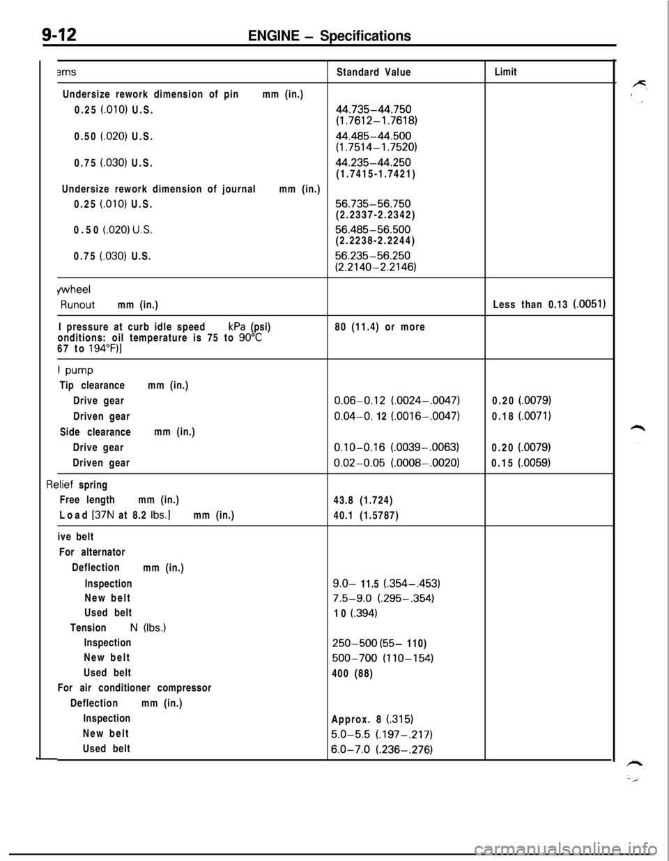
9-12ENGINE - Specifications3msStandard ValueLimit
Undersize rework dimension of pinmm (in.)
0.25
f.010) U.S.44.735-44.750
(1.7612-1.7618)0.50
(.020) U.S.44.485-44.500
(1.7514-1.7520)0.75
(030) U.S.44.235-44.250(1.7415-1.7421)
Undersize rework dimension of journalmm (in.)
0.25
(.OlO) U.S.56.735-56.750(2.2337-2.2342)
0.50
(020) U.S.56.485-56.500(2.2238-2.2244)
0.75
(.030) U.S.56.235-56.250
(2.2140-2.2146)
wheelRunoutmm (in.)Less than 0.13
(0051)I pressure at curb idle speedkPa (psi)80 (11.4) or more
onditions: oil temperature is 75 to
90°C67 to 194”F)l
1 w-wTip clearancemm (in.)
Drive gear
0.06-0.12 (.0024-.0047)0.20 i.0079)Driven gear
0.04-O. 12 (.0016-.0047)0.18 (.0071)Side clearancemm (in.)
Drive gear
0.10-0.16 (.0039-.0063)0.20 (.0079)Driven gear
0.02-0.05 (.0008-.0020)0.15 (.0059)
rlief spring
Free lengthmm (in.)
43.8 (1.724)
Load
[37N at 8.2 Ibs.]mm (in.)
40.1 (1.5787)
ive belt
For alternator
Deflection
mm (in.)
Inspection
9.0- 11.5 (.354-,453)New belt
7.5-9.0 (.295-.354)Used belt
10
i.394)TensionN (Ibs.)
Inspection
250-500 (55- 110)
New belt
500-700 (110-154)Used belt
400 (88)
For air conditioner compressor
Deflectionmm (in.)
Inspection
Approx. 8
(315)New belt
5.0-5.5 (.197-.217)Used belt
6.0-7.0 (.236-.276)