steering wheel adjustment MITSUBISHI ECLIPSE 1991 Service Manual
[x] Cancel search | Manufacturer: MITSUBISHI, Model Year: 1991, Model line: ECLIPSE, Model: MITSUBISHI ECLIPSE 1991Pages: 1216, PDF Size: 67.42 MB
Page 57 of 1216
FRONT SUSPENSION - service Adjustment Procedures/Hub and Knuckle2-9
3.For each half turn of the left and right tie rods, the toe-in willbe adjusted by 6 mm
(24 in.).
4. After making the adjustments, use a turning radius gauge
to confirm that the steering wheel turning angle is within
the standard value range. (Refer to GROUP 19-Service
Adjustment Procedures.)
WHEEL BEARING ADJUSTMENTN02FCM
Bearing preload is pre-set to the specified value by design andtherefore can not be adjusted.
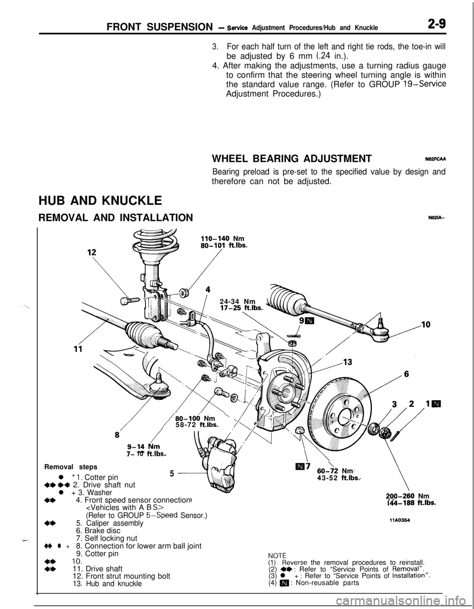
HUB AND KNUCKLE
REMOVAL AND INSTALLATION
NOZIA-
110-140 Nm80-101 ft.lbs.
/24-34 Nm
7- 10ft.lbs.
/80-106 Nm’58-72 ft.lbs.Removal steps
l *
1. Cotter pin5
+w ~~ 2. Drive shaft nutl + 3. Washer
+I)4. Front speed sensor connection
60->2 Nm
43-52 ft.lbs.
-70-260 Nm.A-188 ft.lbs.
(Refer to GROUP 5-Speed
Sensor.)
4*5. Caliper assembly11Ams46. Brake disc
7. Self locking nut
+e l +8. Connection for lower arm ball joint
9. Cotter pin
::
10.ivkeverse the removal procedures to reinstall.
11. Drive shaft
(2) +* : Refer to “Service Points of Removql”.
12. Front strut mounting bolt(3) l + : Refer to “Service Points of Installation”.
13. Hub and knuckle(4) a : Non-reusable parts
Page 92 of 1216
2-44FRONT SUSPENSION -Centermember and Crossmember
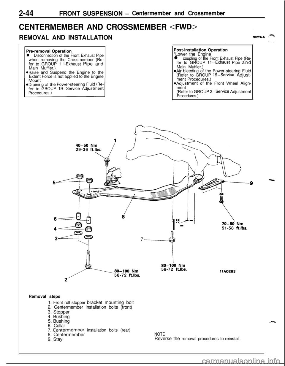
CENTERMEMBER AND CROSSMEMBER
REMOVAL AND INSTALLATION
Pre-removal Operation
l Disconnection of the Front Exhaust Pipewhen removing the Crossmember (Re-
fer to GROUP 1 l-Exhaust Pipe and
Main Muffler.)
@Raise and Suspend the Engine to the
Extent Force is not applied to the EnginePost-installation Operation
*Lower the Enginel coupling of the Front Exhaust Pipe (Re-fer to GROUP ll-Exhaust Pipe and
Main Muffler.)
@Air bleeding of the Power-steering Fluid
(Refer to GROUP 19-Service Adjust-
ment Procedures.)*Adjustment of the Front Wheel Align-
ment
(Refer to GROUP
2-Service AdjustmentProcedures.)
40-50 Nm
29-36 ft.lbs.
! *J
I”---
7
9
80-100 Nm
58-72 ft.lbs.
\80-100 Nm
58-72 ft.lbs.
70-86 Nm
51-58 ft.lbs.llA0283
Removal steps
1. Front roll stopper bracket mounting bolt
2. Centermember installation bolts (front)3. Stopper
4. Bushing
5. Bushing
6. Collar7. Centermember installation bolts (rear)
8. Centermember
9. StayNOTEReverse the removal procedures to reinstall.
4
Page 193 of 1216
BRAKES - Brake Pedal5-53
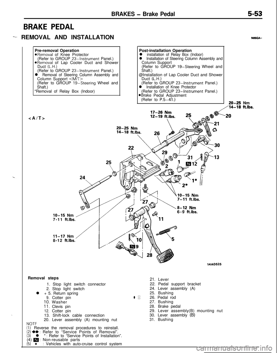
BRAKE PEDAL
-I REMOVAL AND INSTALLATION
.Pre-removal Operation
aRemoval of Knee Protector
(Refer to GROUP 23%Instrument Panel.)
ORemoval of Lap Cooler Duct and Shower
Duct (L.H.)(Refer to GROUP 23-Instrument Panel.)l Removal of Steering Column Assembly andColumn Support
(Refer to GROUP
19-Steering Wheel andShaft.)*Removal of Relay Box (Indoor)
NO5OA--Post-installation Operation
l installation of Relay Box (Indoor)l Installation of Steering Column Assembly andColumn Support
(Refer to GROUP 19-Steering Wheel and
Shaft.)@Installation of Lap Cooler Duct and Shower
Duct
(L.H.)(Refer to GROUP 23-Instrument Panel.)l Installation of Knee Protector(Refer to GROUP 23-Instrument Panel.)aBrake Pedal Adjustment
(Refer to P.5-41.)20-25 Nm
,‘14-18 ft.lbs.
IO-15 Nm /7-11 ft.lbs.
/
11-17 Nm
8-12 ftlbs.6-9
ftlbs.Removal steps
1. Stop light switch connector
2. Stop light switch
l + 5. Return spring
9.Cotter pin10.Washer11.Clevis pin12.Cotter pin
13. Shift-lock cable connection
20. Lever assembly (A) mounting nut
NOTF(i, Reverse the removal procedures to reinstall.(2) 4I) : Refer to “Service Points of Removal”.(3) l * : Refer to “Service Points of Installation”.
(4) m : Non-reusable parts
(5) *: Vehicles with auto-cruise control system
14A0525
l *
21.Lever
22. Pedal support bracket
24. Lever assembly (A)
25.Bushing
26. Pedal rod
27.Bushing
28.Brake pedal
29. Lever assembly(B) mounting nut
30. Lever assembly
(B)31.Bushing
.20
Page 237 of 1216
CLUTCH - Clutch Pedal6-7
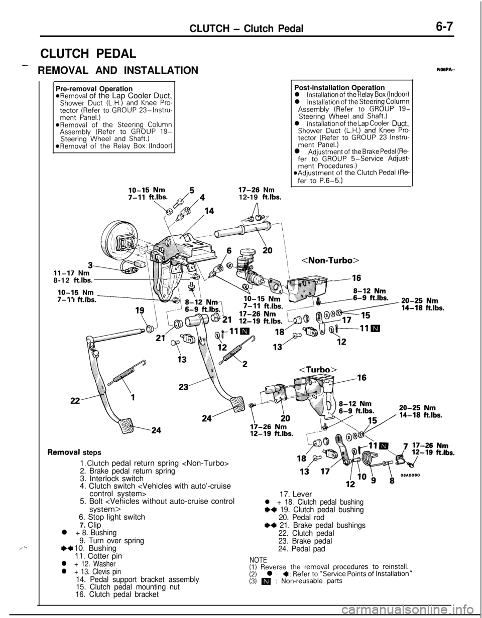
CLUTCH PEDAL
-. REMOVAL AND INSTALLATIONNOSPA-
.“-Pre-removal Operation
*Removal of the Lap Cooler Duct,Shower Duct (L.H.) and Knee Pro-tector (Refer to GROUP 23%lnstru-ment Panel.)*Removal of the Steering ColumnAssembly (Refer to GROUP 19-Steering Wheel and Shaft.)*Removal of the Relay Box (Indoor)
17-26 Nm
12-19 ft.lbs.
11-17 Nm
8-12 ft.lbs.
IO-15 Nm’ tl(i/\:/ Fl/Yv .1-m.---I- I I KIDS.Post-installation Operation
l installation of the Relay Box (Indoor)l installation of the Steering ColumnAssembly (Refer to GROUP 19-Steering Wheel and Shaft.)l installation of the Lap Cooler Duct,Shower Duct (L.H.) and Knee Pro-tector (Refer to GROUP 23 Instru-ment Panel.)l Adjustment of the Brake Pedal (Re-fer to GROUP 5-Service Adjust-ment Procedures.)aAdjustment of the Clutch Pedal (Re-
fer to P.6-5.)
:k -16
20-25 Nm
14-f8 ft.lbs.
Removal steps
I, Clutch pedal return spring
4. Clutch switch
5. Bolt
7. Clip
l + 8. Bushing
9. Turn over spring
e+ IO. Bushing11. Cotter pinl + 12. Washerl + 13. Clevis pin14. Pedal support bracket assembly
15. Clutch pedal mounting nut
16. Clutch pedal bracket17. Lever
l + 18. Clutch pedal bushing~~ 19. Clutch pedal bushing
20. Pedal rod
e+ 21. Brake pedal bushings
22. Clutch pedal
23. Brake pedal
24. Pedal pad
NOTE(1) Reverse the removal procedures to reinstall.(2) l + : Refer to “Service Points of (3) m : Non-reusable parts
Page 309 of 1216
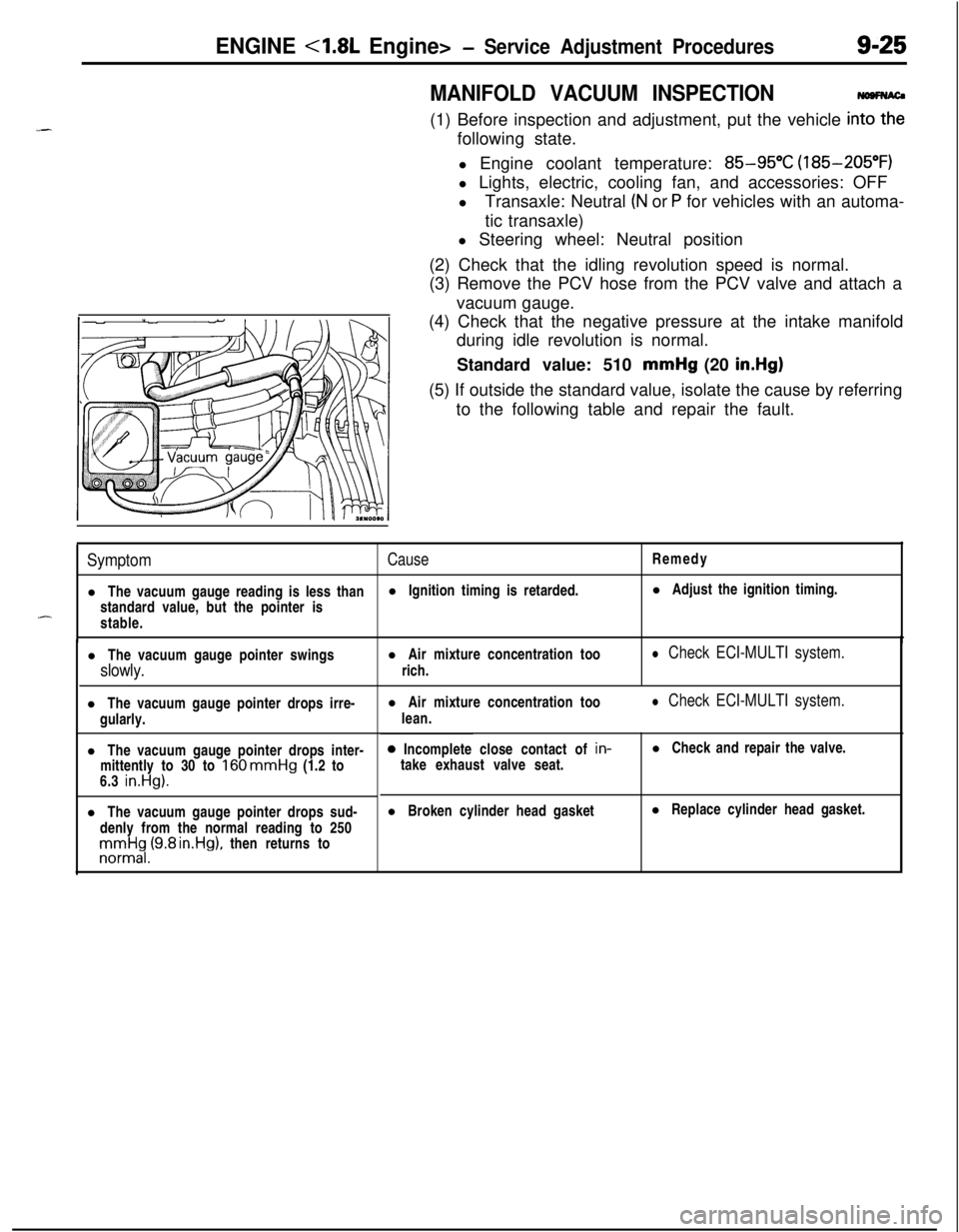
ENGINE <1.8L Engine>- Service Adjustment Procedures9-25
MANIFOLD VACUUM INSPECTION(1) Before inspection and adjustment, put the vehicle
in=following state.
l Engine coolant temperature:
85-95°C (185-205°F)
l Lights, electric, cooling fan, and accessories: OFF
lTransaxle: Neutral
(N or P for vehicles with an automa-
tic transaxle)
l Steering wheel: Neutral position
(2) Check that the idling revolution speed is normal.
(3) Remove the PCV hose from the PCV valve and attach a
vacuum gauge.
(4) Check that the negative pressure at the intake manifold
during idle revolution is normal.
Standard value: 510 mmHg (20
in.Hg)(5) If outside the standard value, isolate the cause by referring
to the following table and repair the fault.
SymptomCauseRemedy
l The vacuum gauge reading is less thanl Ignition timing is retarded.l Adjust the ignition timing.
standard value, but the pointer is
-stable.
l The vacuum gauge pointer swingsl Air mixture concentration too
slowly.rich.
l Check ECI-MULTI system.l The vacuum gauge pointer drops irre-
gularly.
l The vacuum gauge pointer drops inter-
mittently to 30 to
160 mmHg (1.2 to
6.3 in.Hg).l The vacuum gauge pointer drops sud-
denly from the normal reading to 250rronnrt$,(9.8 rn.Hg), then returns tol Air mixture concentration too
lean.
l Check ECI-MULTI system.0 Incomplete close contact of in-
take exhaust valve seat.l Check and repair the valve.
l Broken cylinder head gasketl Replace cylinder head gasket.
Page 310 of 1216
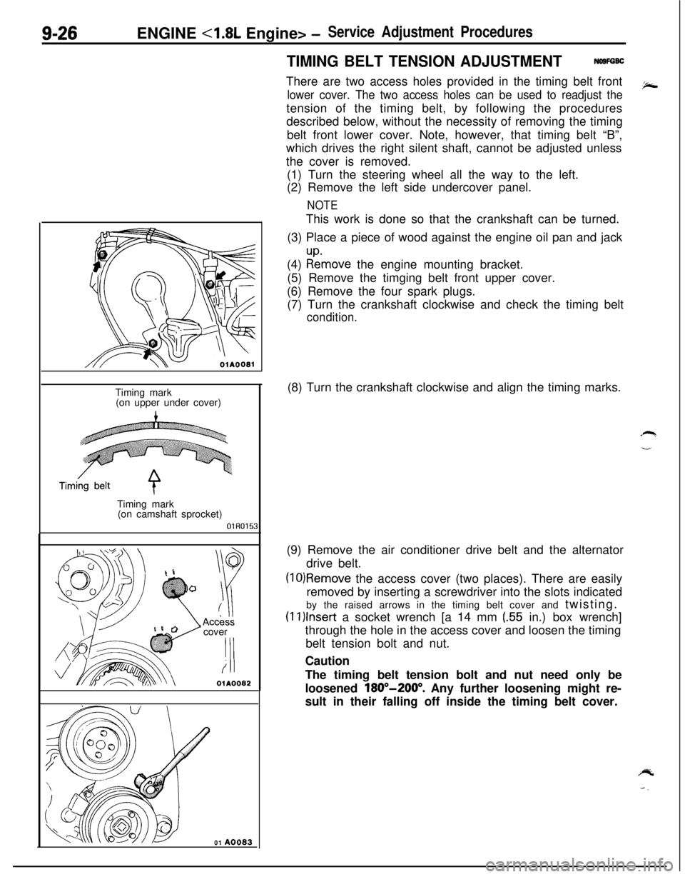
9-26ENGINE <1.8L Engine> -Service Adjustment Procedures
TIMING BELT TENSION ADJUSTMENTNOSFGBCThere are two access holes provided in the timing belt front
lower cover. The two access holes can be used to readjust thetension of the timing belt, by following the procedures
described below, without the necessity of removing the timing
belt front lower cover. Note, however, that timing belt “B”,
which drives the right silent shaft, cannot be adjusted unless
the cover is removed.
(1) Turn the steering wheel all the way to the left.
(2) Remove the left side undercover panel.
NOTEThis work is done so that the crankshaft can be turned.
(3) Place a piece of wood against the engine oil pan and jack
(4)
:tmove the engine mounting bracket.
(5) Remove the timging belt front upper cover.
(6) Remove the four spark plugs.
(7) Turn the crankshaft clockwise and check the timing belt
condition.
OlAOOBlTiming mark
(on upper under cover)
Timing mark
(on camshaft sprocket)
OlR0153cover
‘I!i
OlA0082
01 A0083(8) Turn the crankshaft clockwise and align the timing marks.
(9) Remove the air conditioner drive belt and the alternator
drive belt.
(10)Remove the access cover (two places). There are easily
removed by inserting a screwdriver into the slots indicated
by the raised arrows in the timing belt cover and twisting.
(1l)lnser-t a socket wrench [a 14 mm (.55 in.) box wrench]
through the hole in the access cover and loosen the timing
belt tension bolt and nut.
Caution
The timing belt tension bolt and nut need only be
loosened
180”-200”. Any further loosening might re-
sult in their falling off inside the timing belt cover.
Page 359 of 1216
_-
a--ENGINE
<2.0L DOHC Engine> -Service Adjustment Procedures9-75
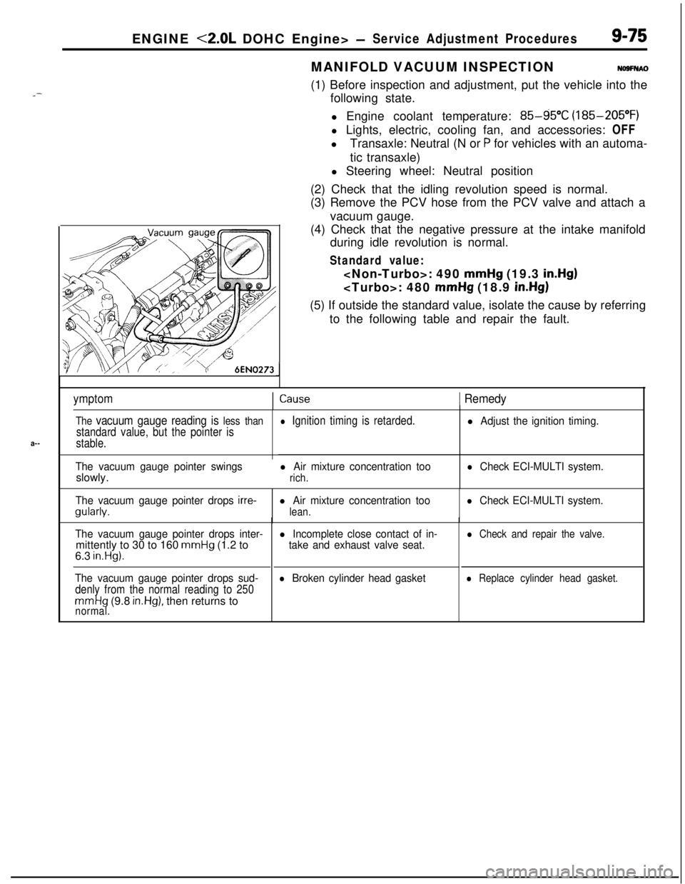
JMANIFOLD VACUUM INSPECTION
NO9FNAO(1) Before inspection and adjustment, put the vehicle into the
following state.
l Engine coolant temperature:
85-g5”C (185-205°F)
l Lights, electric, cooling fan, and accessories: OFF
lTransaxle: Neutral (N or
P for vehicles with an automa-
tic transaxle)
l Steering wheel: Neutral position
(2) Check that the idling revolution speed is normal.
(3) Remove the PCV hose from the PCV valve and attach a
vacuum gauge.
(4) Check that the negative pressure at the intake manifold
during idle revolution is normal.
Standard value:
mmHg (19.3 in.Hg)
mmHg (18.9 in.Hg)(5) If outside the standard value, isolate the cause by referring
to the following table and repair the fault.
ymptomICause1 Remedy
The vacuum gauge reading is less than
standard value, but the pointer is
stable.
The vacuum gauge pointer swingsslowly.
l Ignition timing is retarded.
l Air mixture concentration too
rich.
l Adjust the ignition timing.
l Check ECI-MULTI system.
The vacuum gauge pointer drops
irre-gularly.l Air mixture concentration too
lean.
l Check ECI-MULTI system.
The vacuum gauge pointer drops inter-mittently to 30 to 160
mmHg (1.2 to
6.3 in.Hg).
The vacuum gauge pointer drops sud-
denly from the normal reading to 250
mmHg (9.8 in.Hg), then returns tonormal.
l Incomplete close contact of in-
take and exhaust valve seat.
l Broken cylinder head gasket
l Check and repair the valve.
l Replace cylinder head gasket.
Page 495 of 1216
FUEL SYSTEM - Service Adjustment Procedures <1.8L Engine>l-4-41
SERVICE ADJUSTMENT PROCEDURES
CURB IDLE SPEED INSPECTION
CautionNlIFiiAE
The improper setting (throttle valve opening) will increase
exhaust gas temperature at deceleration, reducing catalystlife greatly and deteriorating exhaust gas cleaning per-
formance. It also has effect on fuel consumption and
engine braking.
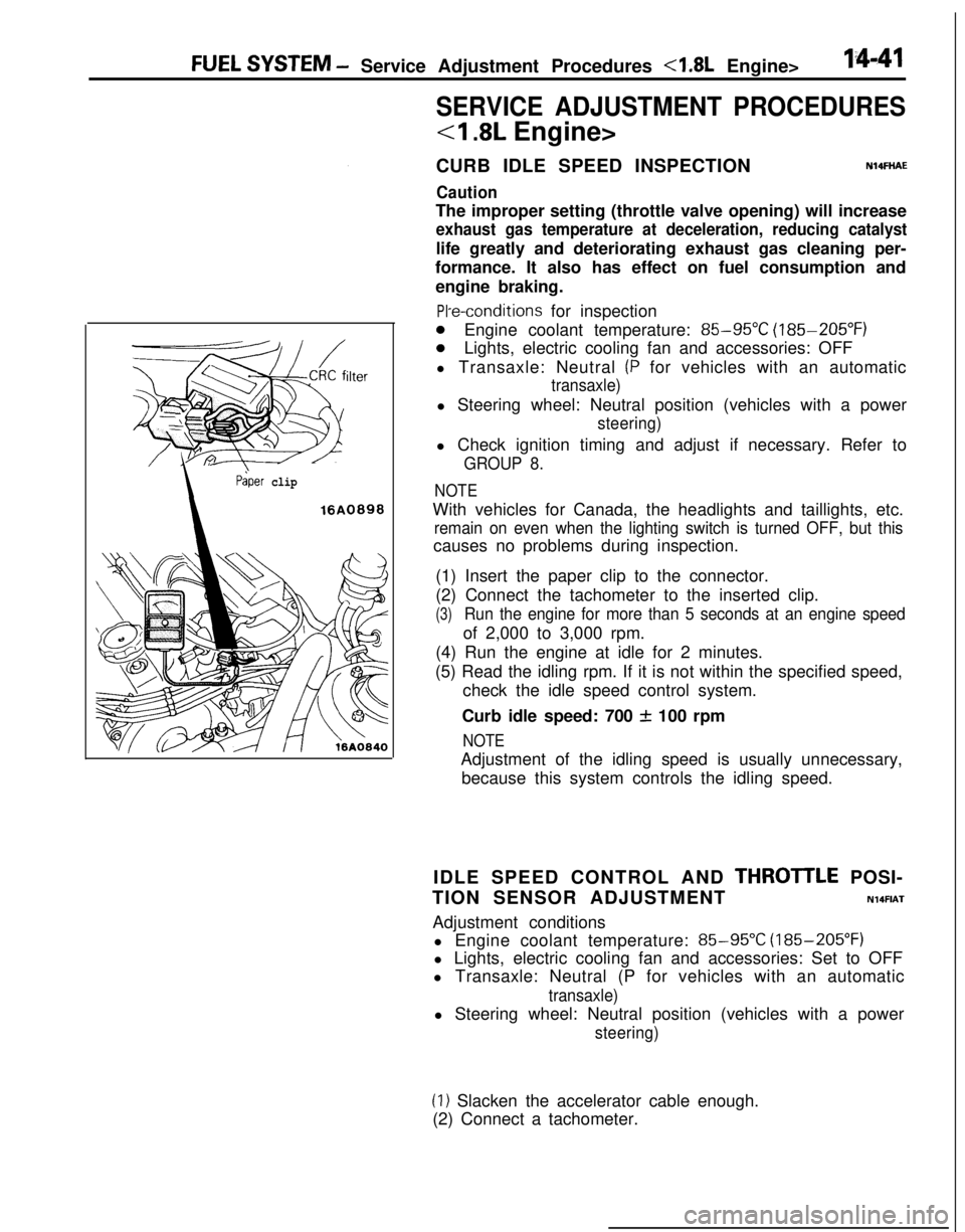
ilter
Paper clip
16A0898
PI-e-conditions for inspection
0Engine coolant temperature: 85-95°C (185-205°F)
0Lights, electric cooling fan and accessories: OFF
l Transaxle: Neutral
(P for vehicles with an automatic
transaxle)l Steering wheel: Neutral position (vehicles with a power
steering)l Check ignition timing and adjust if necessary. Refer to
GROUP 8.
NOTEWith vehicles for Canada, the headlights and taillights, etc.
remain on even when the lighting switch is turned OFF, but thiscauses no problems during inspection.
(1) Insert the paper clip to the connector.
(2) Connect the tachometer to the inserted clip.
(3)Run the engine for more than 5 seconds at an engine speedof 2,000 to 3,000 rpm.
(4) Run the engine at idle for 2 minutes.
(5) Read the idling rpm. If it is not within the specified speed,
check the idle speed control system.
Curb idle speed: 700
f 100 rpm
NOTEAdjustment of the idling speed is usually unnecessary,
because this system controls the idling speed.
IDLE SPEED CONTROL AND
THROTlLE POSI-
TION SENSOR ADJUSTMENT
N14FIATAdjustment conditions
l Engine coolant temperature:
85-95X (185-205°F)
l Lights, electric cooling fan and accessories: Set to OFF
l Transaxle: Neutral (P for vehicles with an automatic
transaxle)l Steering wheel: Neutral position (vehicles with a power
steering)
(1) Slacken the accelerator cable enough.
(2) Connect a tachometer.
Page 502 of 1216
14-48FUEL SYSTEM - Service Adjustment Procedures <2.0L Engine>
SERVICE ADJUSTMENT PROCEDURES
<2.0L DOHC Engine>
CURB IDLE SPEED INSPECTION
Caution
N14FHADThe improper setting (throttle valve opening) will increase
exhaust gas temperature at deceleration, reducing
catalys-tic converter life greatly and deteriorating exhaust gas
cleaning performance. It also has effect on fuel ‘consump-
tion and engine braking.
Pre-conditions for inspection
l Engine coolant temperature:
85-95°C (185-205°F)
l Lights, electric cooling fan and accessories: OFF
lTransaxle: Neutral (P for vehicles with automatic transaxle)l Steering wheel: Neutral position (vehicles with a power-
steering)l Check ignition timing and adjust if necessary. Refer to
GROUP 8.
NOTEWith vehicles for Canada, the headlights and taillights, etc.
remain on even when the lighting switch is turned OFF, but thiscauses no problems during inspection.
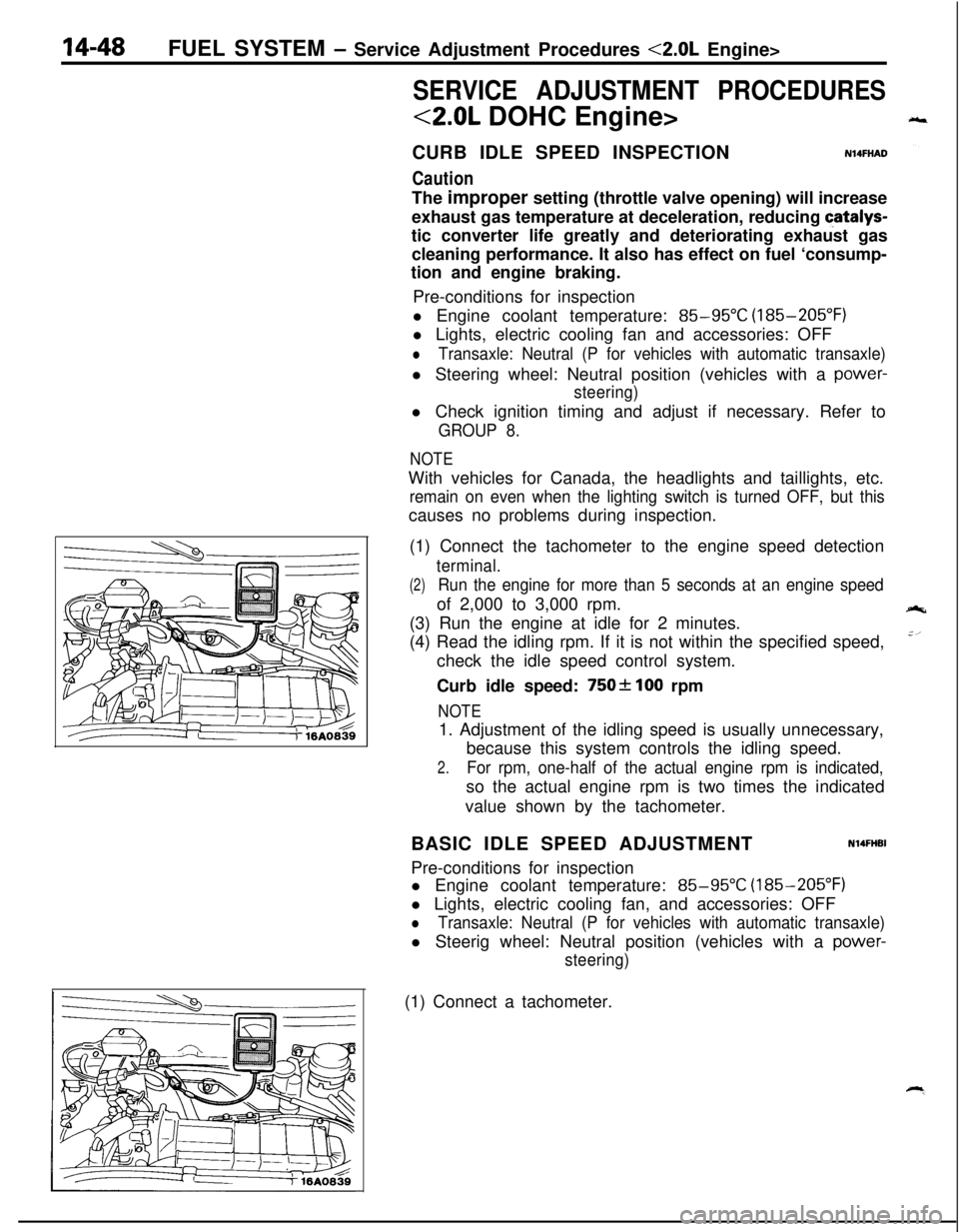
(1) Connect the tachometer to the engine speed detection
terminal.
(2)Run the engine for more than 5 seconds at an engine speedof 2,000 to 3,000 rpm.
(3) Run the engine at idle for 2 minutes.
(4) Read the idling rpm. If it is not within the specified speed,
check the idle speed control system.
Curb idle speed:
750f 100 rpm
NOTE1. Adjustment of the idling speed is usually unnecessary,
because this system controls the idling speed.
2.For rpm, one-half of the actual engine rpm is indicated,so the actual engine rpm is two times the indicated
value shown by the tachometer.
BASIC IDLE SPEED ADJUSTMENT
N14FHBIPre-conditions for inspection
l Engine coolant temperature:
85-95°C (185-205°F)
l Lights, electric cooling fan, and accessories: OFF
lTransaxle: Neutral (P for vehicles with automatic transaxle)l Steerig wheel: Neutral position (vehicles with a
power-
steering)(1) Connect a tachometer.
Page 649 of 1216
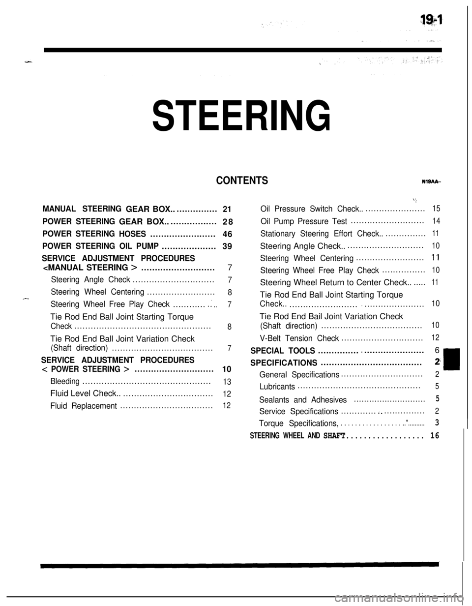
STEERING
CONTENTSNISAA-
MANUAL STEERINGGEAR BOX.................21
POWER STEERINGGEAR BOX...................
28
POWER STEERING
HOSES........................
46
POWER STEERING OIL PUMP....................39
SERVICE ADJUSTMENT PROCEDURES
Steering Angle Check..............................7
Steering Wheel Centering.........................8
Steering Wheel Free Play Check.............:..7Tie Rod End Ball Joint Starting Torque
Check..................................................8Tie Rod End Ball Joint Variation Check
(Shaft direction).....................................7
SERVICE ADJUSTMENT PROCEDURES
< POWER STEERING >.............................
10
Bleeding...............................................13Fluid Level Check...................................
12
Fluid Replacement..................................12
i;,
Oil Pressure Switch Check........................15
Oil Pump Pressure Test...........................14
Stationary Steering Effort Check.................11Steering Angle Check..............................
10
Steering Wheel Centering.........................1 1
Steering Wheel Free Play Check................10Steering Wheel Return to Center Check.......
11Tie Rod End Ball Joint Starting Torque
Check..................................................10Tie Rod End Bail Joint Variation Check
(Shaft direction).....................................10
V-Belt Tension Check..............................12
SPECIAL TOOLS......................................6
SPECIFICATIONS.....................................2;
General Specifications..............................2
Lubricants.............................................5
Sealants and Adhesives............................5
Service Specifications.............‘................2
Torque Specifications,. . . . . . . . . . . . . . . . . ..*..........3
STEERING WHEEL AND SHAFT.................. 16