tow MITSUBISHI ECLIPSE 1991 Service Manual
[x] Cancel search | Manufacturer: MITSUBISHI, Model Year: 1991, Model line: ECLIPSE, Model: MITSUBISHI ECLIPSE 1991Pages: 1216, PDF Size: 67.42 MB
Page 19 of 1216
c
--INTRODUCTION AND MASTER
TROUBLESHOOTtNG - Towing and Hoi&gT9
I-
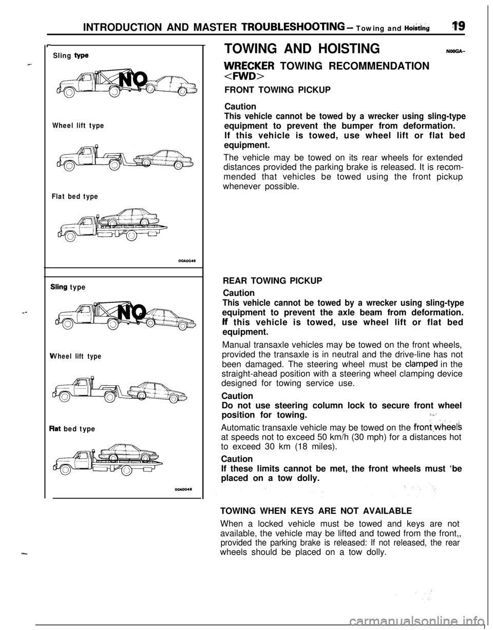
Sling type
Wheel lift type
Flat bed type
iling type
Vheel lift type
lat bed type
TOWING AND HOISTINGNOOGA-
llJ/RE;~R TOWING RECOMMENDATION
FRONT TOWING PICKUP
Caution
This vehicle cannot be towed by a wrecker using sling-typeequipment to prevent the bumper from deformation.
If this vehicle is towed, use wheel lift or flat bed
equipment.
The vehicle may be towed on its rear wheels for extended
distances provided the parking brake is released. It is recom-
mended that vehicles be towed using the front pickup
whenever possible.
REAR TOWING PICKUP
Caution
This vehicle cannot be towed by a wrecker using sling-typeequipment to prevent the axle beam from deformation.lf this vehicle is towed, use wheel lift or flat bed
equipment.
Manual transaxle vehicles may be towed on the front wheels,
provided the transaxle is in neutral and the drive-line has not
been damaged. The steering wheel must be
clam,ped in the
straight-ahead position with a steering wheel clamping device
designed for towing service use.
Caution
Do not use steering column lock to secure front wheel
position for towing.
3,“’Automatic transaxle vehicle may be towed on the
frontwheelsat speeds not to exceed 50 km/h (30 mph) for a distances hot
to exceed 30 km (18 miles).
Caution
If these limits cannot be met, the front wheels must ‘be
placed on a tow dolly.
TOWING WHEN KEYS ARE NOT AVAILABLE
When a locked vehicle must be towed and keys are not
available, the vehicle may be lifted and towed from the front,,
provided the parking brake is released: If not released, the rearwheels should be placed on a tow dolly.
I
Page 20 of 1216
20INTRODUCTION AND MASTER TROUBLESHOOTING - Towing and Hoisting
Frame contact support location
OOAOI 71
I
The following precautions should be taken when
towin the
vehicle.
1.DO NOT LIFT OR TOW THE VEHICLE BY ATTACHING TOOR WRAPPING AROUND THE BUMPER.
2. Any loose or protruding parts of damaged vehicle such as
hoods, doors, fenders, trim, etc., should be secured prior tomoving the vehicle.
3.Operator should refrain from going under a vehicle while it
is lifted by the towing equipment, unless the vehicle in
adequately supported by satefy stands.
4. Never allow passengers to ride in a towed vehicle.
5. State and local rules and regulations must be followed
when towing a vehicle.
Refer to the section “Special Handling Instructions for AWD
Models”.
HOISTING
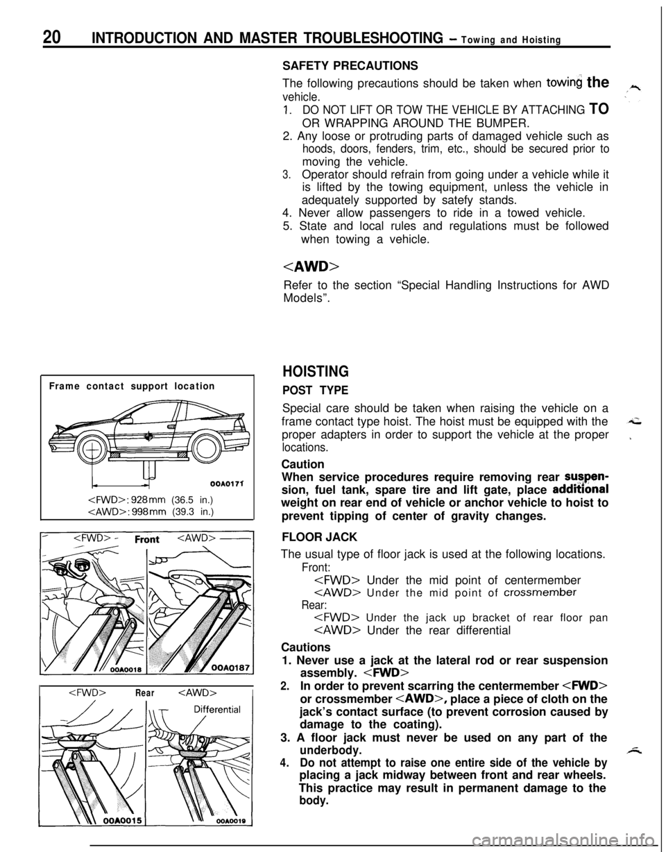
POST TYPESpecial care should be taken when raising the vehicle on a
frame contact type hoist. The hoist must be equipped with the
proper adapters in order to support the vehicle at the proper
locations.Caution
When service procedures require removing rear sutpen-
sion, fuel tank, spare tire and lift gate, place addmonal
weight on rear end of vehicle or anchor vehicle to hoist to
prevent tipping of center of gravity changes.
FLOOR JACK
The usual type of floor jack is used at the following locations.
Front:
Rear:
Cautions
1. Never use a jack at the lateral rod or rear suspension
assembly.
2.In order to prevent scarring the centermember
jack’s contact surface (to prevent corrosion caused by
damage to the coating).
3. A floor jack must never be used on any part of the
underbody.
4.Do not attempt to raise one entire side of the vehicle byplacing a jack midway between front and rear wheels.
This practice may result in permanent damage to the
body.
Page 21 of 1216
--
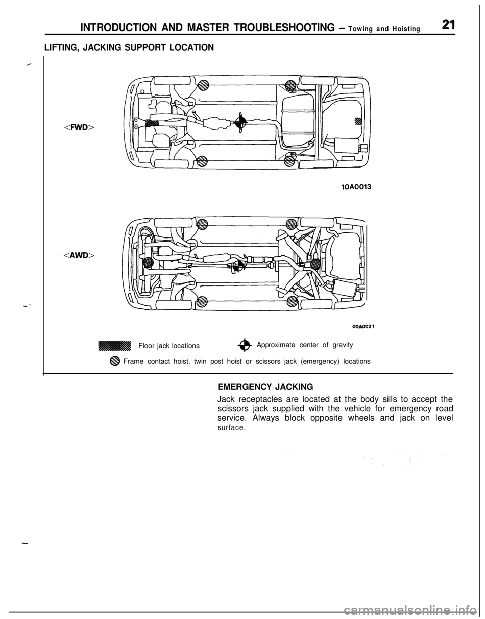
INTRODUCTION AND MASTER TROUBLESHOOTING - Towing and Hoisting2”1LIFTING, JACKING SUPPORT LOCATION
-4WD>
lOAFloor jack locations
OOAOO2 1
*Approximate center of gravity
@ Frame contact hoist, twin post hoist or scissors jack (emergency) locations
EMERGENCY JACKING
Jack receptacles are located at the body sills to accept the
scissors jack supplied with the vehicle for emergency road
service. Always block opposite wheels and jack on level
surface.
Page 22 of 1216
22 INTRODUCTION AND MASTER TROUBLESHOOTING - %%c%:k! ‘nstructions
SPECIAL HANDLING INSTRUCTIONS FOR AWD MODELSNWUAAB
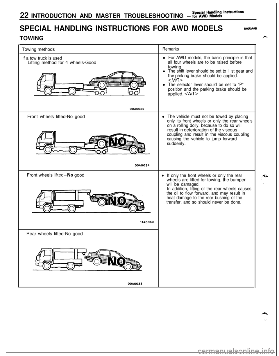
TOWINGTowing methods
If a tow truck is usedLifting method for 4 wheels-Good
Remarks
l For AWD models, the basic principle is that
all four wheels are to be raised beforetowing.
l The shift lever should be set to 1 st gear and
thhrting brake should be applied.
l The selector lever should be set to “P”
position and the parking brake should beapplied.
OOAO032Front wheels lifted-No good
l The vehicle must not be towed by placing
only its front wheels or only the rear wheels
on a rolling dolly, because to do so willresult in deterioration of the viscous
coupling and result in the viscous coupling
causing the vehicle to jump forward
suddenly.OOA0034
Front wheels
IifteddNo goodlIf only the front wheels or only the rearwheels are lifted for towing, the bumper
will be damaged.
In addition, lifting of the rear wheels causes
the oil to flow forward, and may result in
heat damage to the rear bushing of the
transfer, and so should never be done.
llA0060Rear wheels lifted-No goodOOA0033
Page 36 of 1216
o-2LUBRICATION AND MAINTENANCE - General Information
GENERAL INFORMATIONNGQPA--Maintenance and lubrication service recommenda-
tions have been compiled to provide maximum
protection for the vehicle owner’s investment
against all reasonable types of driving conditions.
Since these conditions vary with the individual
vehicle owner’s driving habits, the area in which the
vehicle is operated and the type of driving to which
the vehicle is subjected, it is necessary to prescribe
lubrication and maintenance service on a time
frequency as well as mileage interval basis.
Oils, lubricants and greases are classified and
graded according to standards recommended by theSociety of Automotive Engineers (SAE), the Amer-
ican Petroleum Institute (API) and the National
Lubricating Grease Institute
(NLGI).MAINTENANCE SCHEDULES
Information for service maintenance is provided
under “SCHEDULED MAINTENANCE TABLE”.
Three schedules are provided; one for “Required
Maintenance”, one for “General Maintenance” and
one for “Severe Usage Service”.
Item numbers in the “SCHEDULED MAINTE-
NANCE TABLE” correspond to the item numbers in
the “MAINTENANCE SERVICE” section.
SEVERE SERVICEVehicles operating under severe service conditions
will require more frequent service.
Component service information is included in
appropriate units for vehicles operating under one ormore of the following conditions:
1.Trailer towing or police, taxi, or commercial type
operation2. Operation of Vehicle
(1) Short-trip operation at freezing temperature
(engine not thoroughly warmed up)
(2) More than 50% operation in heavy city
traffic during hot weather above
32°C (90°F)(3) Extensive idling
(4) Driving in sandy areas
(5) Driving in salty areas
(6) Driving in dusty conditions
ENGINE OIL
The SAE grade number indicates the viscosity of
engine oils, for example, SAE 30, which is a single
grade oil. Engine oils are also identified by a dual
number, for example, SAE
lOW-30, which indicates
a multigrade oil.
The API classification system defines oil perform-
ance in terms of engine usage. Only engine oil
designed “For Service SG” or “For Service
SGKD”,when available, should be used. These oils contain
sufficient chemical additives to provide maximum
engine protection. Both the SAE grade and the API
designation can be found on the container.Caution
Test results submitted to EPA have shown thatlaboratory animals develop skin cancer after
prolonged contact with used engine oil. Accor-
dingly, the potential exists for humans
to de-
velop a number of skin disorders, including
cancer, from such exposure to used engine oil.
Care should be’ taken, therefore, when changingengine oil, to minimize the amount and length of
exposure time to used engine
pi! on your skin.
Protective clothing and gloves, that cannot be
penetrated by oil, should be worn. The skin
should be thoroughly washed with soap and
water, or use waterless hand cleaner, to removeany used engine oil. Do not use gasoline,
thinners, or solvents.
GEAR LUBRICANTSThe SAE grade number also indicates the viscosity
of Multi-Purpose Gear Lubricants.
The API classfication system defines gear lubricants
in terms of usage. Typically gear lubricants conform-ing to API
GL-4 or GL-5 with a viscosity of SAE
75W-85W are recommended for manual transaxle.
LUBRICANTS
- GREASES
Semi-solid lubricants, bear the NLGI designation andare further classified as grades 0, 1, 2, 3 etc.
Whenever “Chassis Lubricant” is specified, Multi-
Purpose Grease,
NLGI grade 2 should be used.
MOPAR Multi-Mileage Lubricant, P&t Number
2525035 or equivalent, meets these requirement
and is recommended.
FUEL USAGE STATEMENT
Use gasolines having a minimum anti-knock index
(Octane Value) of 87,
(R + M)/2. This designation is
comparable to a Research Octane Number of 91.
Unleaded gasolines only must be used in vehicles
equipped with catalyst emission control systems.
All vehicles, so equipped, have labels located on the
instrument panel and on the back of fuel filler lid that
state, “UNLEADED GASOLINE ONLY”. These vehi-
cles also have fuel filler tubes especially designed toaccept the smaller diameter unleaded gasoline
dispensing nozzles only.
MATERIALS ADDED
TO FUELIndiscriminate use of fuel system cleanng agents
should be avoided. Many of these materials in-
tended for gum and varnish removal may contain
highly active solvents or similar ingredients that can
be harmful to gasket and diaphragm materials usedin fuel system component parts.
Page 38 of 1216
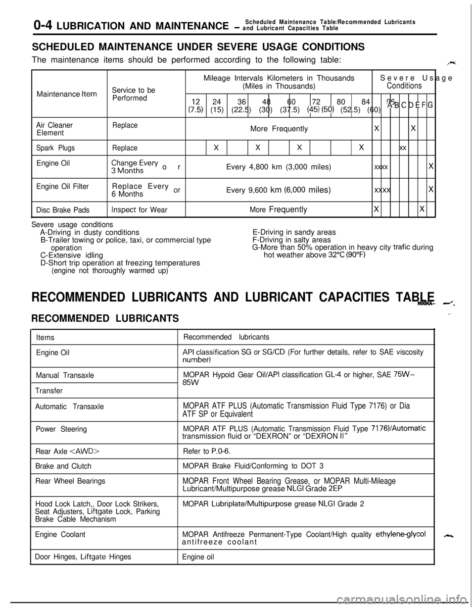
0-4 LUBRICATION AND MAINTENANCEScheduled Maintenance Table/Recommended Lubricants- and Lubricant Capacities TableSCHEDULED MAINTENANCE UNDER SEVERE USAGE CONDITIONS
The maintenance items should be performed according to the following table:
F.Mileage Intervals Kilometers in ThousandsSevere Usage
Service to be(Miles in Thousands)ConditionsMaintenance
Item
Performed24 36 48 60 72 80 84 96
(:,:) (15) (22.5) (30) (37.5) (45) (50) (52.5) (60) * B ’ D E F G
Air CleanerReplaceElementMore FrequentlyXX
Spark PlugsReplace
XXXx xx
Engine Oil$$~~~h~vev orEvery 4,800 km (3,000 miles)xxxx x
Engine Oil FilterReplace Every or6 MonthsEvery 9,600 km (6,000 miles)xxxx x
Disc Brake PadsInspect for WearMore FrequentlyXX
Severe usage conditionsA-Driving in dusty conditionsE-Driving in sandy areas
B-Trailer towing or police, taxi, or commercial typeF-Driving in salty areas
operationG-More than 50% operation in heavy city trafic during
C-Extensive idlinghot weather above 32°C (90°F)D-Short trip operation at freezing temperatures
(engine not thoroughly warmed up)
RECOMMENDED LUBRICANTS AND LUBRICANT CAPACITIES TABLENOONA- --z.
RECOMMENDED LUBRICANTS
Items
Engine Oil
Manual Transaxle
TransferRecommended lubricantskF&cesisification
SG or SG/CD (For further details, refer to SAE viscosity
MOPAR Hypoid Gear
Oil/API classification GL4 or higher, SAE 75W-85W
Automatic TransaxleMOPAR ATF PLUS (Automatic Transmission Fluid Type 7176) or Dia
ATF SP or Equivalent
Power SteeringMOPAR ATF PLUS (Automatic Transmission Fluid Type 7176VAutomatictransmission fluid or “DEXRON” or “DEXRON II”
Rear Axle
Brake and Clutch
Rear Wheel BearingsRefer to
P.O-6.
MOPAR Brake Fluid/Conforming to DOT 3
MOPAR Front Wheel Bearing Grease, or MOPAR Multi-MileageLubricant/Multipurpose grease NLGI Grade 2EP
Hood Lock Latch,, Door Lock Strikers,
Seat Adjusters, Lrftgate Lock, Parking
Brake Cable MechanismMOPAR Lubriplate/Multipurpose grease NLGI Grade 2
Engine CoolantMOPAR Antifreeze Permanent-Type Coolant/High quality
ethylene-glycolantifreeze coolant
Door Hinges, Liftgate Hinges
Engine oil
/
N
Page 56 of 1216
2-8FRONT SUSPENSION - Service Adjustment Procedures
SERVICE ADJUSTMENT PROCEDURES
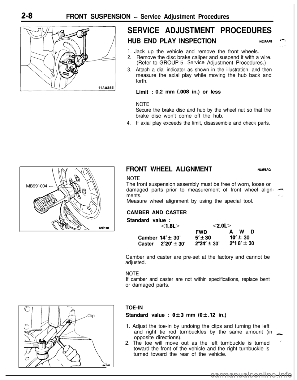
HUB END PLAY INSPECTIONNO2FAAB --- ’
1. Jack up the vehicle and remove the front wheels.
2.Remove the disc brake caliper and suspend it with a wire.
(Refer to GROUP
5-Service Adjustment Procedures.)
3.Attach a dial indicator as shown in the illustration, and thenmeasure the axial play while moving the hub back and
forth.Limit
: 0.2 mm (.008 in.) or less
NOTE
Secure the brake disc and hub by the wheel nut so that thebrake disc won’t come off the hub.
4.If axial play exceeds the limit, disassemble and check parts.
FRONT WHEEL ALIGNMENTNOZFBAQ
NOTEThe front suspension assembly must be free of worn, loose or
damaged parts prior to measurement of front wheel align-
A
ments.--l
Measure wheel alignment by using the special tool.
CAMBER AND CASTER
Standard value
:
<1.8L><2.0L>
FWDAWD
Camber
14’+ 30’5’k3010’f 30
Caster250 + 30’2”24’ + 30’29 8’ f 30Camber and caster are pre-set at the factory and cannot be
adjusted.
NOTE
If camber and caster are not within specifications, replace bentor damaged parts.
TOE-INStandard value
:Of3 mm (Of.12 in.)
1. Adjust the toe-in by undoing the clips and turning the left
and right tie rod turnbuckles by the same amount (in
-opposite directions).
2. The toe will move out as the left turnbuckle is turned
- ,’toward the front of the vehicle and the right turnbuckle is
turned toward the rear of the vehicle.
Page 114 of 1216
3-12REAR AXLE - Drive ShaftTrailing arm
/c-4171
F
MB960931
1 lA0039Trailing arm
M B990799
11 A0040
7
llAO263
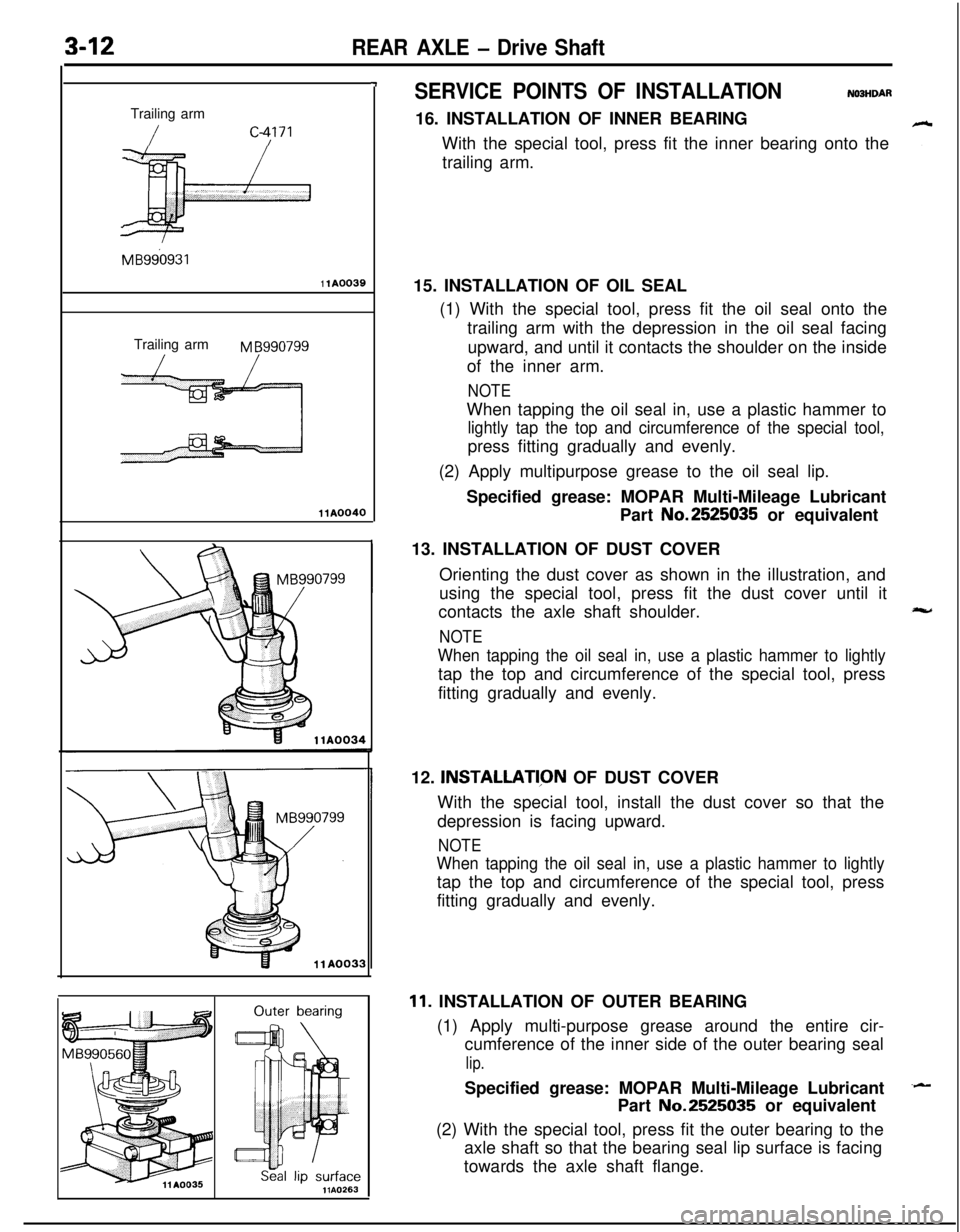
SERVICE POINTS OF INSTALLATIONN03HDAR16. INSTALLATION OF INNER BEARING
With the special tool, press fit the inner bearing onto the
trailing arm.
15. INSTALLATION OF OIL SEAL
(1) With the special tool, press fit the oil seal onto the
trailing arm with the depression in the oil seal facing
upward, and until it contacts the shoulder on the inside
of the inner arm.
NOTEWhen tapping the oil seal in, use a plastic hammer to
lightly tap the top and circumference of the special tool,press fitting gradually and evenly.
(2) Apply multipurpose grease to the oil seal lip.
Specified grease: MOPAR Multi-Mileage Lubricant
Part No.2525035 or equivalent
13. INSTALLATION OF DUST COVER
Orienting the dust cover as shown in the illustration, and
using the special tool, press fit the dust cover until it
contacts the axle shaft shoulder.
NOTE
When tapping the oil seal in, use a plastic hammer to lightlytap the top and circumference of the special tool, press
fitting gradually and evenly.
12.
INSTALLATl,ON OF DUST COVER
With the special tool, install the dust cover so that the
depression is facing upward.
NOTE
When tapping the oil seal in, use a plastic hammer to lightlytap the top and circumference of the special tool, press
fitting gradually and evenly.
11. INSTALLATION OF OUTER BEARING
(1) Apply multi-purpose grease around the entire cir-
cumference of the inner side of the outer bearing seal
lip.Specified grease: MOPAR Multi-Mileage Lubricant
Part No.2525035 or equivalent
(2) With the special tool, press fit the outer bearing to the
axle shaft so that the bearing seal lip surface is facing
towards the axle shaft flange.
Page 115 of 1216
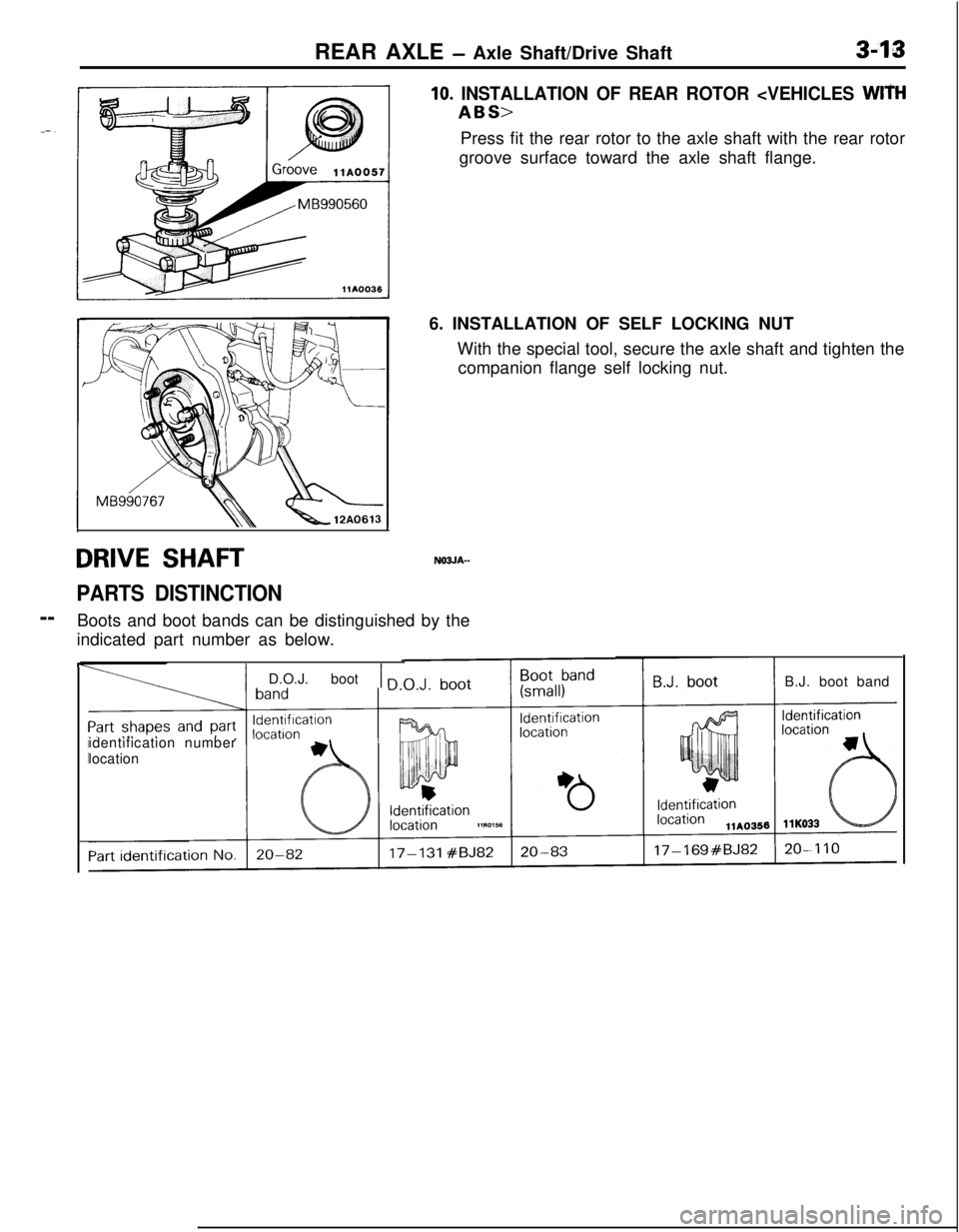
REAR AXLE - Axle Shaft/Drive Shaft3-13
DRIVE SHAFTN03JA--
PARTS DISTINCTION--
Boots and boot bands can be distinguished by the
indicated part number as below.
10. INSTALLATION OF REAR ROTOR
groove surface toward the axle shaft flange.
6. INSTALLATION OF SELF LOCKING NUT
With the special tool, secure the axle shaft and tighten the
companion flange self locking nut.
F
I
IIidentification number
location
1 D.O.J. boot 1 nB.J. boot band
Page 235 of 1216
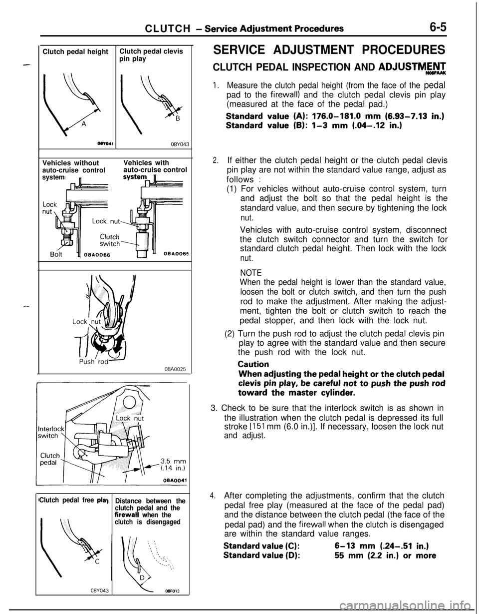
CLUTCH - Service Adjustment Procedures6-5Clutch pedal height
b
AClutch pedal clevis
pin play
08YO43Vehicles without
auto-cruise control
systemVehicles with
auto-cruise control
08A0025I
Clutch pedal free pIa\
08YO43
Distance between the
clutch pedal and thefirewall
when theclutch is disengaged
SERVICE ADJUSTMENT PROCEDURES
CLUTCH PEDAL INSPECTION AND ADJUSTMY’,
1.Measure the clutch pedal height (from the face of the pedalpad to the
firewall) and the clutch pedal clevis pin play
(measured at the face of the pedal pad.)
Standard value (A): 176.0-181.0 mm (6.93-7.13 in.)
Standard value (B): l-3 mm (.04-.12 in.)
2.If either the clutch pedal height or the clutch pedal clevis
pin play are not within the standard value range, adjust as
follows
:(1) For vehicles without auto-cruise control system, turn
and adjust the bolt so that the pedal height is the
standard value, and then secure by tightening the lock
nut.Vehicles with auto-cruise control system, disconnect
the clutch switch connector and turn the switch for
standard clutch pedal height. Then lock with the lock
nut.
NOTE
When the pedal height is lower than the standard value,
loosen the bolt or clutch switch, and then turn the pushrod to make the adjustment. After making the adjust-
ment, tighten the bolt or clutch switch to reach the
pedal stopper, and then lock with the lock nut.
(2) Turn the push rod to adjust the clutch pedal clevis pin
play to agree with the standard value and then secure
the push rod with the lock nut.
CautionWhen adjusting the
pedal height or the clutch pedal
clevis pin play, be careful not to push the push rodtoward the master
cylinder.3. Check to be sure that the interlock switch is as shown in
the illustration when the clutch pedal is depressed its full
stroke
[151 mm (6.0 in.)]. If necessary, loosen the lock nut
and adjust.
4.After completing the adjustments, confirm that the clutch
pedal free play (measured at the face of the pedal pad)
and the distance between the clutch pedal (the face of the
pedal pad) and the
firewall when the clutch is disengaged
are within the standard value ranges.
Standard value (C):6-13 mm (.24-.51 in.)
Standard value (D):55 mm (2.2 in.) or more