cooling MITSUBISHI ECLIPSE 1991 Workshop Manual
[x] Cancel search | Manufacturer: MITSUBISHI, Model Year: 1991, Model line: ECLIPSE, Model: MITSUBISHI ECLIPSE 1991Pages: 1216, PDF Size: 67.42 MB
Page 309 of 1216
ENGINE <1.8L Engine>- Service Adjustment Procedures9-25
MANIFOLD VACUUM INSPECTION(1) Before inspection and adjustment, put the vehicle
in=following state.
l Engine coolant temperature:
85-95°C (185-205°F)
l Lights, electric, cooling fan, and accessories: OFF
lTransaxle: Neutral
(N or P for vehicles with an automa-
tic transaxle)
l Steering wheel: Neutral position
(2) Check that the idling revolution speed is normal.
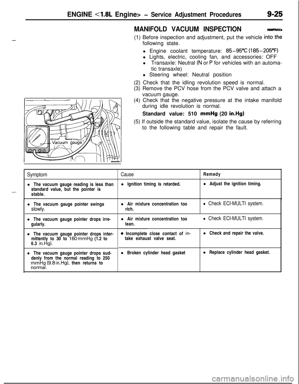
(3) Remove the PCV hose from the PCV valve and attach a
vacuum gauge.
(4) Check that the negative pressure at the intake manifold
during idle revolution is normal.
Standard value: 510 mmHg (20
in.Hg)(5) If outside the standard value, isolate the cause by referring
to the following table and repair the fault.
SymptomCauseRemedy
l The vacuum gauge reading is less thanl Ignition timing is retarded.l Adjust the ignition timing.
standard value, but the pointer is
-stable.
l The vacuum gauge pointer swingsl Air mixture concentration too
slowly.rich.
l Check ECI-MULTI system.l The vacuum gauge pointer drops irre-
gularly.
l The vacuum gauge pointer drops inter-
mittently to 30 to
160 mmHg (1.2 to
6.3 in.Hg).l The vacuum gauge pointer drops sud-
denly from the normal reading to 250rronnrt$,(9.8 rn.Hg), then returns tol Air mixture concentration too
lean.
l Check ECI-MULTI system.0 Incomplete close contact of in-
take exhaust valve seat.l Check and repair the valve.
l Broken cylinder head gasketl Replace cylinder head gasket.
Page 359 of 1216
_-
a--ENGINE
<2.0L DOHC Engine> -Service Adjustment Procedures9-75
JMANIFOLD VACUUM INSPECTION
NO9FNAO(1) Before inspection and adjustment, put the vehicle into the
following state.
l Engine coolant temperature:
85-g5”C (185-205°F)
l Lights, electric, cooling fan, and accessories: OFF
lTransaxle: Neutral (N or
P for vehicles with an automa-
tic transaxle)
l Steering wheel: Neutral position
(2) Check that the idling revolution speed is normal.
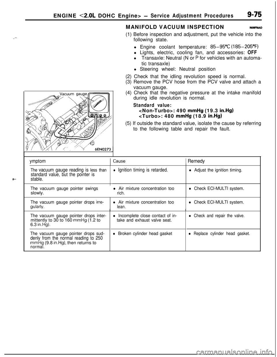
(3) Remove the PCV hose from the PCV valve and attach a
vacuum gauge.
(4) Check that the negative pressure at the intake manifold
during idle revolution is normal.
Standard value:
mmHg (19.3 in.Hg)
mmHg (18.9 in.Hg)(5) If outside the standard value, isolate the cause by referring
to the following table and repair the fault.
ymptomICause1 Remedy
The vacuum gauge reading is less than
standard value, but the pointer is
stable.
The vacuum gauge pointer swingsslowly.
l Ignition timing is retarded.
l Air mixture concentration too
rich.
l Adjust the ignition timing.
l Check ECI-MULTI system.
The vacuum gauge pointer drops
irre-gularly.l Air mixture concentration too
lean.
l Check ECI-MULTI system.
The vacuum gauge pointer drops inter-mittently to 30 to 160
mmHg (1.2 to
6.3 in.Hg).
The vacuum gauge pointer drops sud-
denly from the normal reading to 250
mmHg (9.8 in.Hg), then returns tonormal.
l Incomplete close contact of in-
take and exhaust valve seat.
l Broken cylinder head gasket
l Check and repair the valve.
l Replace cylinder head gasket.
Page 437 of 1216
INTAKE AND EXHAUST - Intake Manifold < 1.8L Engine>1145
SERVICE POINTS OF REMOVALNllMBAI
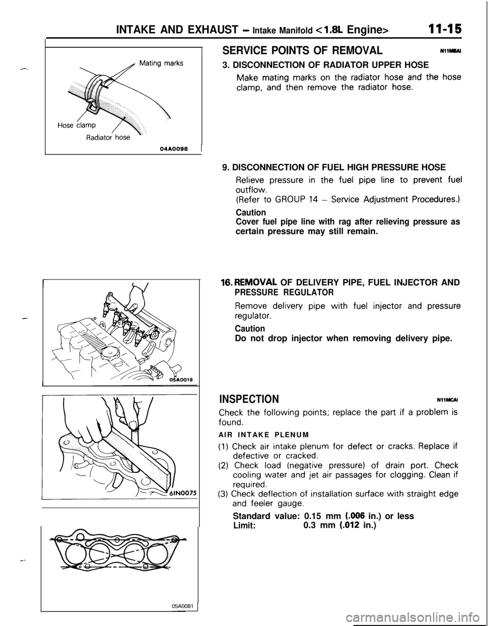
3. DISCONNECTION OF RADIATOR UPPER HOSE
Make mating marks on the radiator hose and the hose
clamp, and then remove the radiator hose.
r
04A0088 19. DISCONNECTION OF FUEL HIGH PRESSURE HOSE
Relieve pressure in the fuel pipe line to prevent fueloutflow.
(Refer to GROUP 14 - Service Adjustment Procedures.)
Caution
Cover fuel pipe line with rag after relieving pressure ascertain pressure may still remain.16.REMOVAL OF DELIVERY PIPE, FUEL INJECTOR AND
PRESSURE REGULATOR
Remove delivery pipe with fuel injector and pressure
regulator.
CautionDo not drop injector when removing delivery pipe.
INSPECTIONNllMCAl
Check the following points; replace the part if a problem isfound.
AIR INTAKE PLENUM
(1) Check air intake plenum for defect or cracks. Replace ifdefective
or cracked.
(2) Check load (negative pressure) of drain port. Check
cooling water and jet air passages for clogging. Clean if
required.
(3) Check deflection of installation surface with straight edge
and feeler gauge.Standard value: 0.15 mm
(.006 in.) or less
Limit:0.3 mm (.012 in.)05AOOB4
Page 438 of 1216
II-16INTAKE AND EXHAUST - Intake Manifold c 1.8L Engine>
05A0033
0580188Mating marksINTAKE MANIFOLD
(1) Check for damage or cracking of any part.+4
(2) Check load (negative pressure) of drain port. Check ,cooling water
and jet air passages for clogging. Clean if
required.
(3) Check deflection of installation surface with straight edge
and feeler gauge.Standard value: 0.15 mm
(006 in.) or less
Limit:
0.3 mm (.012 in.)
SERVICE POINTS OF INSTALLATIONNllMDAXa
29. INSTALLATION OF COVER
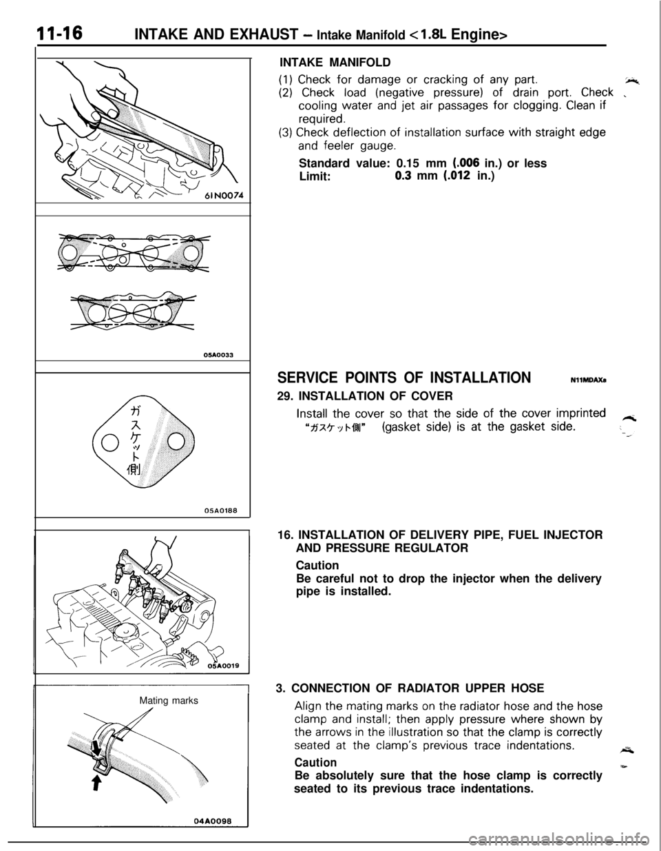
Install the cover so that the side of the cover imprinted
“fj‘x? ‘Y bf4l~(gasket side) is at the gasket side.-T16. INSTALLATION OF DELIVERY PIPE, FUEL INJECTOR
AND PRESSURE REGULATOR
Caution
Be careful not to drop the injector when the delivery
pipe is installed.
3. CONNECTION OF RADIATOR UPPER HOSEAlign the
mating marks on the radiator hose and the hose
clamp and install; then apply pressure where shown bythe
arrows in the illustration so that the clamp is correctly
seated at the clamp’s previous trace indentations.A
Caution
-Be absolutely sure that the hose clamp is correctly
seated to its previous trace indentations.
Page 495 of 1216
FUEL SYSTEM - Service Adjustment Procedures <1.8L Engine>l-4-41
SERVICE ADJUSTMENT PROCEDURES
CURB IDLE SPEED INSPECTION
CautionNlIFiiAE
The improper setting (throttle valve opening) will increase
exhaust gas temperature at deceleration, reducing catalystlife greatly and deteriorating exhaust gas cleaning per-
formance. It also has effect on fuel consumption and
engine braking.
ilter
Paper clip
16A0898
PI-e-conditions for inspection
0Engine coolant temperature: 85-95°C (185-205°F)
0Lights, electric cooling fan and accessories: OFF
l Transaxle: Neutral
(P for vehicles with an automatic
transaxle)l Steering wheel: Neutral position (vehicles with a power
steering)l Check ignition timing and adjust if necessary. Refer to
GROUP 8.
NOTEWith vehicles for Canada, the headlights and taillights, etc.
remain on even when the lighting switch is turned OFF, but thiscauses no problems during inspection.
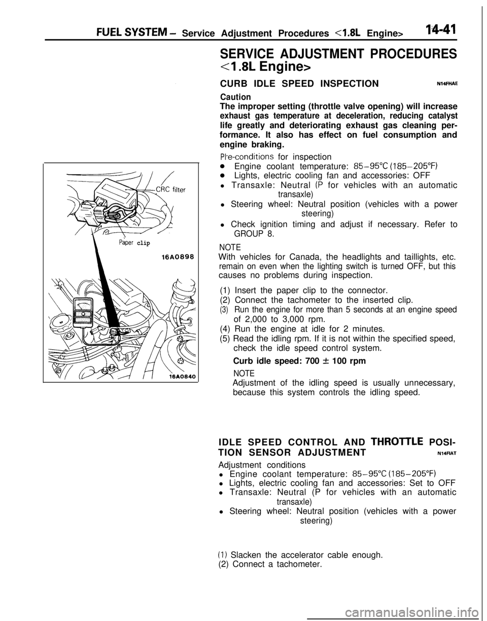
(1) Insert the paper clip to the connector.
(2) Connect the tachometer to the inserted clip.
(3)Run the engine for more than 5 seconds at an engine speedof 2,000 to 3,000 rpm.
(4) Run the engine at idle for 2 minutes.
(5) Read the idling rpm. If it is not within the specified speed,
check the idle speed control system.
Curb idle speed: 700
f 100 rpm
NOTEAdjustment of the idling speed is usually unnecessary,
because this system controls the idling speed.
IDLE SPEED CONTROL AND
THROTlLE POSI-
TION SENSOR ADJUSTMENT
N14FIATAdjustment conditions
l Engine coolant temperature:
85-95X (185-205°F)
l Lights, electric cooling fan and accessories: Set to OFF
l Transaxle: Neutral (P for vehicles with an automatic
transaxle)l Steering wheel: Neutral position (vehicles with a power
steering)
(1) Slacken the accelerator cable enough.
(2) Connect a tachometer.
Page 502 of 1216
14-48FUEL SYSTEM - Service Adjustment Procedures <2.0L Engine>
SERVICE ADJUSTMENT PROCEDURES
<2.0L DOHC Engine>
CURB IDLE SPEED INSPECTION
Caution
N14FHADThe improper setting (throttle valve opening) will increase
exhaust gas temperature at deceleration, reducing
catalys-tic converter life greatly and deteriorating exhaust gas
cleaning performance. It also has effect on fuel ‘consump-
tion and engine braking.
Pre-conditions for inspection
l Engine coolant temperature:
85-95°C (185-205°F)
l Lights, electric cooling fan and accessories: OFF
lTransaxle: Neutral (P for vehicles with automatic transaxle)l Steering wheel: Neutral position (vehicles with a power-
steering)l Check ignition timing and adjust if necessary. Refer to
GROUP 8.
NOTEWith vehicles for Canada, the headlights and taillights, etc.
remain on even when the lighting switch is turned OFF, but thiscauses no problems during inspection.
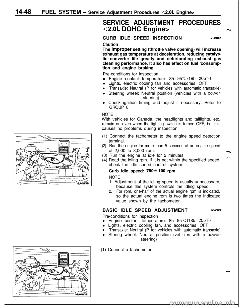
(1) Connect the tachometer to the engine speed detection
terminal.
(2)Run the engine for more than 5 seconds at an engine speedof 2,000 to 3,000 rpm.
(3) Run the engine at idle for 2 minutes.
(4) Read the idling rpm. If it is not within the specified speed,
check the idle speed control system.
Curb idle speed:
750f 100 rpm
NOTE1. Adjustment of the idling speed is usually unnecessary,
because this system controls the idling speed.
2.For rpm, one-half of the actual engine rpm is indicated,so the actual engine rpm is two times the indicated
value shown by the tachometer.
BASIC IDLE SPEED ADJUSTMENT
N14FHBIPre-conditions for inspection
l Engine coolant temperature:
85-95°C (185-205°F)
l Lights, electric cooling fan, and accessories: OFF
lTransaxle: Neutral (P for vehicles with automatic transaxle)l Steerig wheel: Neutral position (vehicles with a
power-
steering)(1) Connect a tachometer.
Page 997 of 1216
AUTOMATIC TRANSAXLE - Front Clutch Assemblv21-303
1750266
MD998337
\
1750264
/TFA0498Clutch
reactior
TFA0424
i
269
SERVICE POINTS OF DISASSEMBLY6. REMOVAL OF SNAP RING
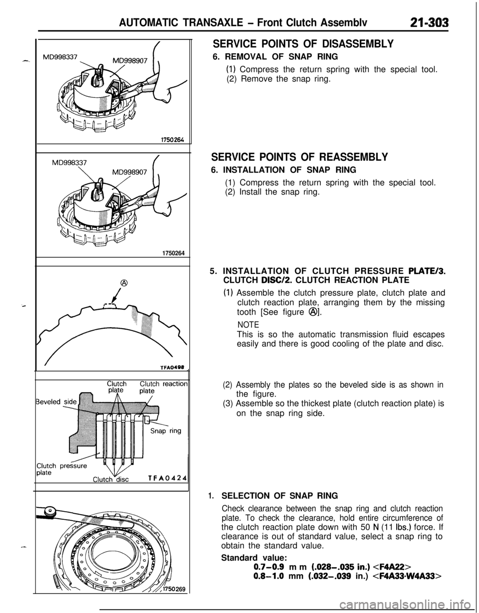
(1) Compress the return spring with the special tool.
(2) Remove the snap ring.
SERVICE POINTS OF REASSEMBLY6. INSTALLATION OF SNAP RING
(1) Compress the return spring with the special tool.
(2) Install the snap ring.
5. INSTALLATION OF CLUTCH PRESSURE
PLATE/3.CLUTCH
DISC/P. CLUTCH REACTION PLATE
(1) Assemble the clutch pressure plate, clutch plate and
clutch reaction plate, arranging them by the missing
tooth [See figure
@I.
NOTEThis is so the automatic transmission fluid escapes
easily and there is good cooling of the plate and disc.
(2) Assembly the plates so the beveled side is as shown inthe figure.
(3) Assemble so the thickest plate (clutch reaction plate) is
on the snap ring side.
1.SELECTION OF SNAP RING
Check clearance between the snap ring and clutch reaction
plate. To check the clearance, hold entire circumference ofthe clutch reaction plate down with 50
N (11 Ibs.) force. If
clearance is out of standard value, select a snap ring to
obtain the standard value.
Standard value:
0.7-0.9 mm (.028-.035 in;)
0.8-1.0 mm (.032-.039 in.)
Page 999 of 1216

AUTOMATIC TRANSAXLE - Rear Clutch Assemblv
MD998337Shear droop
Clutch disc
TFA0501
\1750275
SERVICE POINTS OF DISASSEMBLY12. REMOVAL OF WAVE SPRING
(1) Compress the return spring with the special tool.
(2) Using a screwdriver, remove the wave spring.
SERVICE POINTS OF REASSEMBLY12. INSTALLATION OF WAVE SPRING
(1) Compress return spring with the special tool.
(2) Install the wave spring.
11. INSTALLATION OF CLUTCH PRESSURE
PLATE/IO.CLUTCH
PLATE/8. CLUTCH REACTION PLATE
(1) Install the clutch pressure plate, clutch plates and clutchreaction plate with their missing tooth portions
(@ in
the illustration) in alignment.
NOTE
This design is to facilitate escape of automatic transmis-sion fluid and improve the cooling efficiency of the
plates and disc.
(2) Install the clutch reaction plate with its shear droop
directed as shown in the illustration.
7. SELECTION OF SNAP RING
Check clearance between the snap ring and clutch reaction
plate. To check the clearance, hold entire circumference ofthe clutch reaction plate down with 50
N (11 Ibs.) force. If
clearance is out of standard value, select a snap ring to
obtain the standard value.
Standard value:
0.3-0.5 mm (.012-.020 in.)
Page 1002 of 1216
21-308 AUTOMATIC TRANSAXLE - Rear Clutch Assembly
@
/
(
TFAO240SERVICE POINTS OF
DISASSEM.BLY12. REMOVAL OF SNAP RING
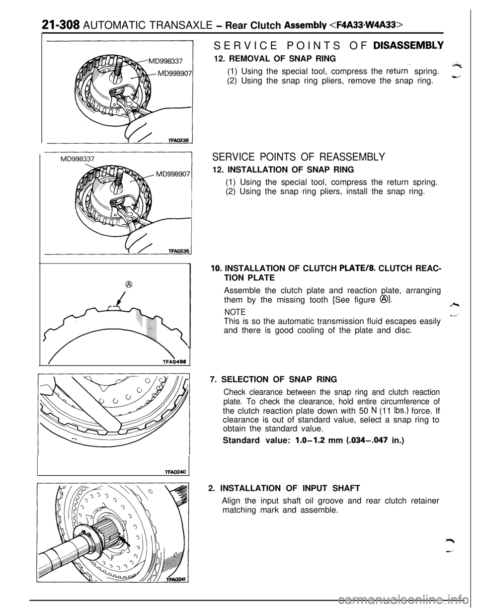
(1) Using the special tool, compress the
returns spring.
(2) Using the snap ring pliers, remove the snap ring.
SERVICE POINTS OF REASSEMBLY12. INSTALLATION OF SNAP RING
(1) Using the special tool, compress the return spring.
(2) Using the snap ring pliers, install the snap ring.
10. INSTALLATION OF CLUTCH PLATE/*. CLUTCH REAC-
TION PLATE
Assemble the clutch plate and reaction plate, arranging
them by the missing tooth [See figure
@I.
NOTEThis is so the automatic transmission fluid escapes easily
and there is good cooling of the plate and disc.
7. SELECTION OF SNAP RING
Check clearance between the snap ring and clutch reaction
plate. To check the clearance, hold entire circumference ofthe clutch reaction plate down with 50
N (11 Ibs.) force. If
clearance is out of standard value, select a snap ring to
obtain the standard value.
Standard value:
1.0-1.2 mm (.034-.047 in.)
2. INSTALLATION OF INPUT SHAFT
Align the input shaft oil groove and rear clutch retainer
matching mark and assemble.
Page 1157 of 1216
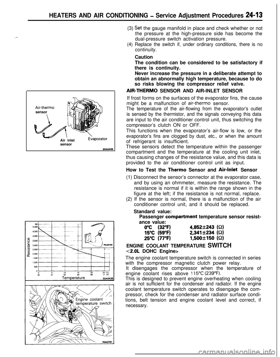
HEATERS AND AIR CONDITIONING - Service Adjustment Procedures 249*I3
--Air-therm0
sensor
Air inlet
sensor
E>aporator(3)
Set the gauge manifold in place and check whether or not
the pressure at the high-pressure side has become the
dual-pressure switch activation pressure.
(4) Replace the switch if, under ordinary conditions, there is no
continuity.Caution
The condition can be considered to be satisfactory if
there is continuity.
Never increase the pressure in a deliberate attempt to
obtain an abnormally high temperature, because to do
so risks blowing the compressor relief valve.AIR-THERM0 SENSOR AND AIR-INLET SENSOR
If frost forms on the surfaces of the evaporator fins, the cause
might be a malfunction of
air-therm0 sensor.
The temperature of the air-flowing from the evaporator’s outlet
is sensed by the thermistor, and the signals conveying this dataare input to the air conditioner control unit, thus switching the
compressor’s clutch ON or OFF.
This functions when the evaporator’s air-flow is low, or the
evaporator’s fins are clogged by dust, etc., or when the amountof refrigerant is insufficient.
These sensors detect the temperature within the passenger
compartment and the temperature at the cooling unit inlet,
thus causing changes of the resistance value, and this data is
provided to the air conditioner control unit as input.
How to Test the Therm0 Sensor and Air-Inlet Sensor
(1) Disconnect the sensor’s connector at the evaporator case,
and by using an ohmmeter, measure the resistance. The
resistance is normal if it is within the range shown in the
figure at the left; if the resistance is not normal, replace.
(2) If the sensor is normal, there is a malfunction of the air
conditioner control unit, and it should be replaced.
Standard value:
Passenger compartment temperature sensor resist-
ance value:
0°C (32°F)4,852+243 (S-2)
15°C (59°F)2,341+234 (S-2)
25°C (77°F)1,500+150 (52)
ENGINE COOLANT TEMPERATURE SWITCH
<2.0L DOHC Engine>
The engine coolant temperature switch is connected in series
with the compressor magnetic clutch power relay.
It disengages the compressor when the temperature of
engine coolant rises above
115°C (239°F).This is designed to prevent engine overheating when cooling
air is not sufficient for the condenser and radiator. If the enginecoolant temperature switch operates to disengage the com-
pressor, check for the condenser and radiator surface condi-
tions, belt tension and engine coolant level and correct, if
necessary.