cooling MITSUBISHI ECLIPSE 1991 Workshop Manual
[x] Cancel search | Manufacturer: MITSUBISHI, Model Year: 1991, Model line: ECLIPSE, Model: MITSUBISHI ECLIPSE 1991Pages: 1216, PDF Size: 67.42 MB
Page 1160 of 1216

24-16 HEATERS AND AIR CONDITIONING - Service Adjustment Procedures
PERFORMANCE TESTN24FWAFa(1) Park the tested vehicle at the area which is not exposed to
the direct sunlight.
(2) Connect a tachometer and manifold gauge set.
(3) Set the controls of the air conditioner as follows:
Air conditioning switch: A/C-ON position
Mode selection lever: Face position
Temperature control lever: Max. cooling position
Air selection lever: Recirculation position
Blower switch: HI (Fast) position
(4) Start engine and adjust rpm to 1,000 with air conditioner
clutch engaged.
(5) Engine should be warmed up with doors, windows close
and hood open.
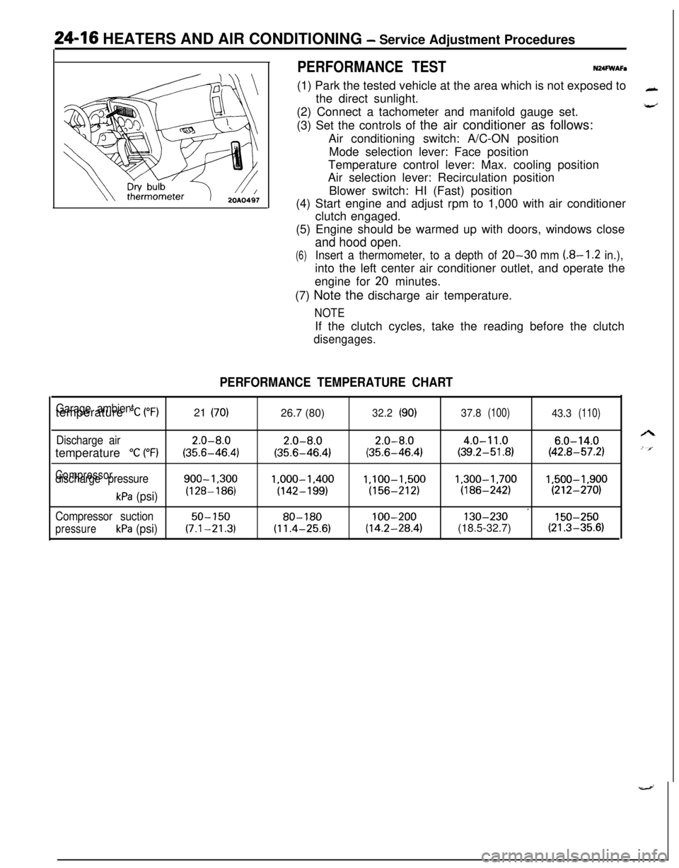
(6)Insert a thermometer, to a depth of 20-30 mm (8-I .2 in.),into the left center air conditioner outlet, and operate the
engine for
20 minutes.
(7) Note the discharge air temperature.
NOTEIf the clutch cycles, take the reading before the clutch
disengages.
PERFORMANCE TEMPERATURE CHART
Garage ambienttemperature “C (“F)21 (70)26.7 (80)32.2(90)37.8(100)43.3(110)
Discharge air2.0-8.02.0-8.02.0-8.04.0-11.06.0-14.0temperature
“C (“F)(35.6-46.4)(35.6-46.4)(35.6-46.4)(39.2-51.8)(42.8-57.2)
Compressordischarge pressure900-1.3001.000-1.400l,lOO-1,5001,300-1,7001,500-1,900
kPa (psi)(128-186)(142-199)(156-212)(186-242)(212-270)
’Compressor suction50-15080-180100-200130-230150-250
pressurekPa (psi)(7.1-21.3)(11.4-25.6)(14.2-28.4)(18.5-32.7)(21.3-35.6)
Page 1169 of 1216

HEATERS AND AIR CONDITIONING - Service Adjustment Procedures 24-25
16A1077
20AO499
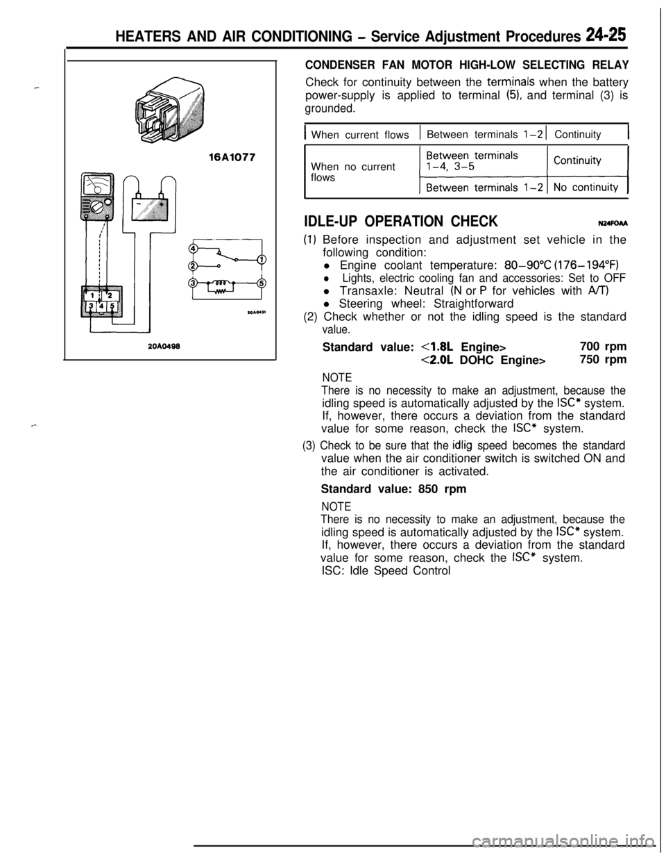
CONDENSER FAN MOTOR HIGH-LOW SELECTING RELAYCheck for continuity between the
term,inals when the battery
power-supply is applied to terminal
(5), and terminal (3) is
grounded.
IWhen current flows1 Between terminals l-2 1 Continuity1When no current
flows
IDLE-UP OPERATION CHECKN24FoAA
(I) Before inspection and adjustment set vehicle in the
following condition:
l Engine coolant temperature:
80-90°C (176-194°F)
lLights, electric cooling fan and accessories: Set to OFFl Transaxle: Neutral
(N or P for vehicles with A/T)l Steering wheel: Straightforward
(2) Check whether or not the idling speed is the standard
value.Standard value:
4.8L Engine>700 rpm
<2.0L DOHC Engine>750 rpm
NOTE
There is no necessity to make an adjustment, because theidling speed is automatically adjusted by the
ISC” system.
If, however, there occurs a deviation from the standard
value for some reason, check the
ISC” system.
(3) Check to be sure that the idlig speed becomes the standardvalue when the air conditioner switch is switched ON and
the air conditioner is activated.
Standard value: 850 rpm
NOTE
There is no necessity to make an adjustment, because theidling speed is automatically adjusted by the
ISC” system.
If, however, there occurs a deviation from the standard
value for some reason, check the
ISC” system.
ISC: Idle Speed Control
Page 1183 of 1216

HEATERS AND AIR CONDITIONING - Compressor24-39
\/20A0400
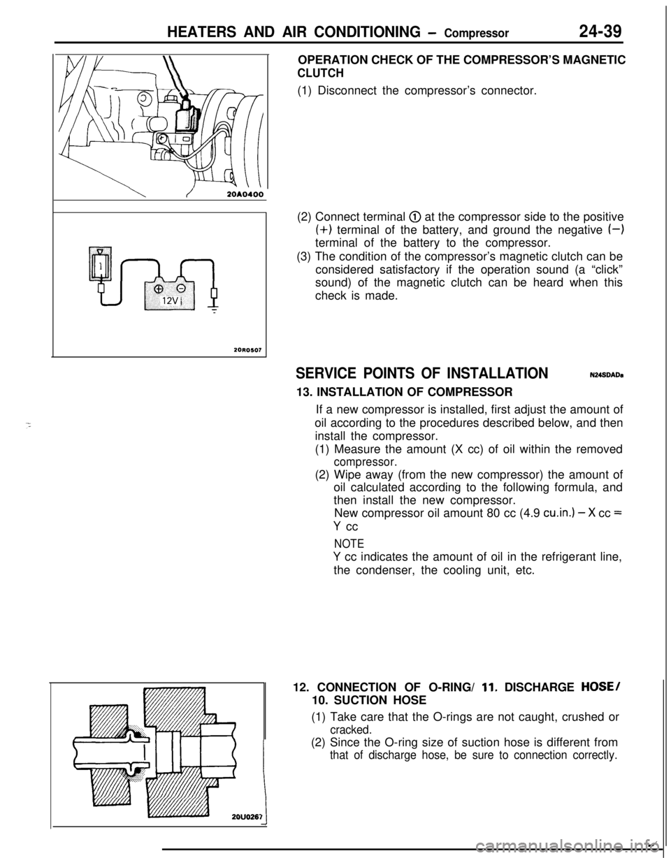
20R0507OPERATION CHECK OF THE COMPRESSOR’S MAGNETIC
CLUTCH(1) Disconnect the compressor’s connector.
(2) Connect terminal
@ at the compressor side to the positive(+) terminal of the battery, and ground the negative
(-)terminal of the battery to the compressor.
(3) The condition of the compressor’s magnetic clutch can be
considered satisfactory if the operation sound (a “click”
sound) of the magnetic clutch can be heard when this
check is made.
SERVICE POINTS OF INSTALLATIONN248DADa13. INSTALLATION OF COMPRESSOR
If a new compressor is installed, first adjust the amount of
oil according to the procedures described below, and then
install the compressor.
(1) Measure the amount (X cc) of oil within the removed
compressor.(2) Wipe away (from the new compressor) the amount of
oil calculated according to the following formula, and
then install the new compressor.
New compressor oil amount 80 cc (4.9
cu.in.) - X cc =
Y cc
NOTE
Y cc indicates the amount of oil in the refrigerant line,
the condenser, the cooling unit, etc.
12. CONNECTION OF O-RING/
11. DISCHARGE HOSE/
10. SUCTION HOSE
(1) Take care that the O-rings are not caught, crushed or
cracked.(2) Since the O-ring size of suction hose is different from
that of discharge hose, be sure to connection correctly.
1t
/