cooling MITSUBISHI ECLIPSE 1991 Owner's Manual
[x] Cancel search | Manufacturer: MITSUBISHI, Model Year: 1991, Model line: ECLIPSE, Model: MITSUBISHI ECLIPSE 1991Pages: 1216, PDF Size: 67.42 MB
Page 264 of 1216
7-16COOLING - Thermostat
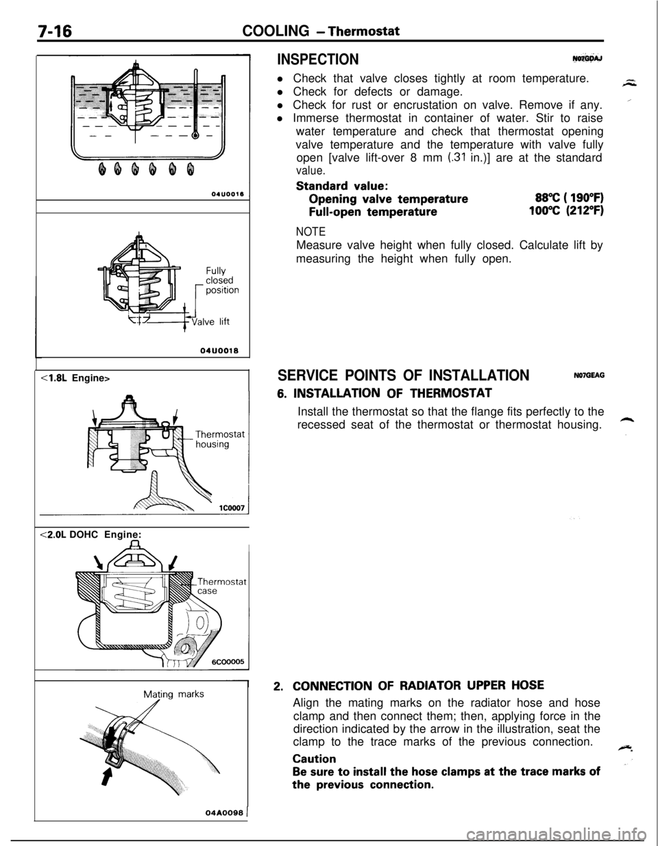
INSPECTIONy+w
l Check that valve closes tightly at room temperature.
l Check for defects or damage.
l Check for rust or encrustation on valve. Remove if any.
l Immerse thermostat in container of water. Stir to raise
water temperature and check that thermostat opening
valve temperature and the temperature with valve fully
open [valve lift-over 8 mm
(.31 in.)] are at the standard
value.Standard
value:Opening
valve temperature
Full-open temperature
88°C ( 190°F)
100°C (212°F)
Fullyclosedpositionve lift
04UOO18<1.8L Engine><2.0L DOHCEngine:
IMating
marks
NOTEMeasure valve height when fully closed. Calculate lift by
measuring the height when fully open.
SERVICE POINTS OF INSTALLATIONNOlGEAG
6. INSTALLATION OF THERMOSTAT
Install the thermostat so that the flange fits perfectly to the
recessed seat of the thermostat or thermostat housing.
2.CONNECTION OF RADIATOR UPPER HOSEAlign the mating marks on the radiator hose and hose
clamp and then connect them; then, applying force in the
direction indicated by the arrow in the illustration, seat the
clamp to the trace marks of the previous connection.
Caution
Be sure to install the hose clamps at the trace marks ofthe
previous connection.
04A0099 )
Page 265 of 1216
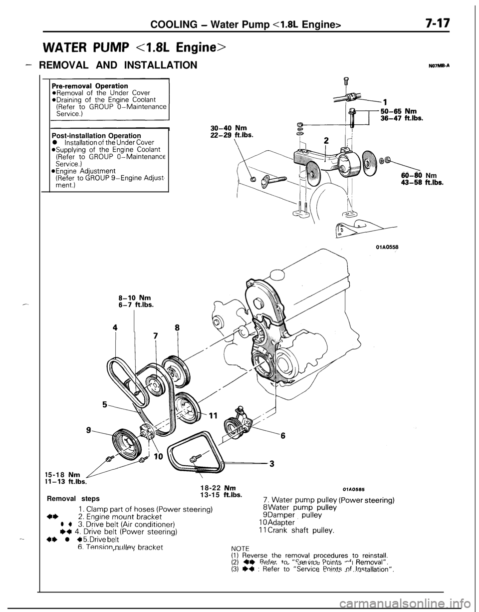
COOLING - Water Pump <1.8L Engine>
WATER PUMP 4.8L Engine>
7-17
- REMOVAL AND INSTALLATION
c.
-_*Draining of
the Engine Coolant(Refer to GROUP O-Maintenance
Post-installation Operation
l installation of the Under Cover@Supplying of the Engine Coolant(Refer to GROUP O-MaintenanceService.)@Engine Adjustment(RR:; to GROUP g-Engine Adjust-
8-10 Nm6-7 ftlbs.
48NOlMB-A
30-40 Nm
22-2g Fbs.
0
60-80 Nm43-58 ft.lbs.5-18
Nm1-13 ft.lbs.18-22 NmRemoval steps13-15 ft.lbs.
1. Clamp part of hoses (Power steering)4+2. Engine mount bracketl +3. Drive belt (Air conditioner)I)+ 4. Drive belt (Power steering)
4+ l + 5. Drive belt
7. Water pump pulleyWater pump pulleyDamper pullevAdapter. ’Crank shaft pulley.
OlAO566
(Powersteering)
6. Tension tx~llev bra&&I\lnTFr--‘--I -‘--‘.--I.VIL(I) Reverse the removal procedures to reinstall.I?\ CI Refer tn “Smvirr rh:-*- -‘ D---./al”,\-, --. I.VIw, .”..-..,u; r”llllb “I “allI”\(3) +4 : Refer to “Service Points nf Instalk_ - .,.__ -. _.._ .-Jion”.
Page 266 of 1216
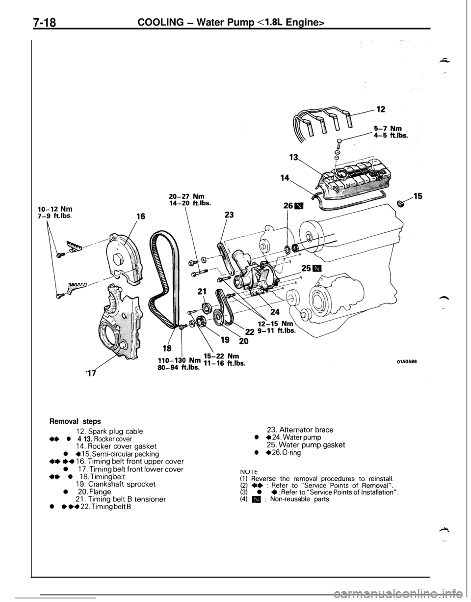
7-18COOLING - Water Pump <1.8L Engine>
lo-12 Nm7-9 ft.lbs.OlA05813
17
Removal steps
12. Spark plug cable+e l 4 13. Rocker cover14. Rocker cover gasket
l + 15. Semi-circular packing~~ e+ 16. Timing belt front upper coverl
17. Timing belt front lower cover+e l 18. Timing belt19. Crankshaft sprocketl 20. Flange21.
Timing belt B tensionerl I) ~~ 22. Timing belt B23.
Alternator bracel + 24. Water pump25.
Water pump gasketl + 26. O-ring
NUlt(I) Reverse the removal procedures to reinstall.(2) ** : Refer to “Service Points of Removal”.(3) l 4 : Refer to “Service Points of Installation”.(4) m : Non-reusable parts
Page 267 of 1216
COOLING - Water Pump <1.8L Engine>749SERVICE POINTS OF REMOVAL
NO’IMCAG
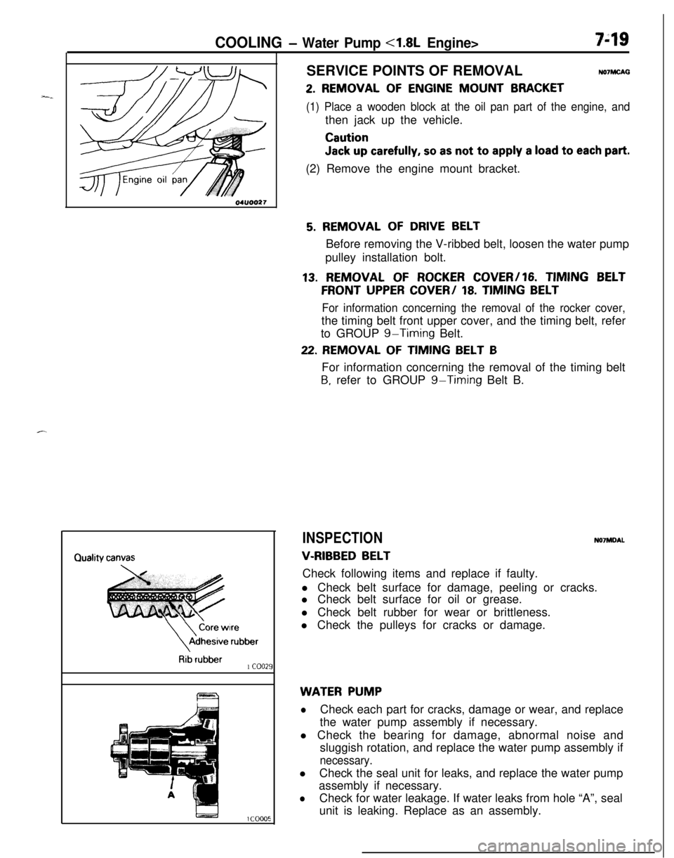
2. REMOVAL OF ENGINE MOUNT BRACKET
(1) Place a wooden block at the oil pan part of the engine, andthen jack up the vehicle.
Caution
Jack up carefully, so as not to apply a load to each part.(2) Remove the engine mount bracket.
\
\
Core wireAdhesive
rubber
Rib rubber1 coo21
5. REMOVAL OF DRIVE BELTBefore removing the V-ribbed belt, loosen the water pump
pulley installation bolt.
13. REMOVAL OF ROCKER COVER/16. TIMING BELT
FRONT UPPER COVER/ 18. TIMING BELT
For information concerning the removal of the rocker cover,the timing belt front upper cover, and the timing belt, refer
to GROUP
g-Timing Belt.
22. REMOVAL OF TIMING BELT BFor information concerning the removal of the timing belt
B, refer to GROUP g-Timing Belt B.
INSPECTIONN07MDAL
V-RIBBED BELTCheck following items and replace if faulty.
l Check belt surface for damage, peeling or cracks.
l Check belt surface for oil or grease.
l Check belt rubber for wear or brittleness.
l Check the pulleys for cracks or damage.
WATER PUMP
lCheck each part for cracks, damage or wear, and replace
the water pump assembly if necessary.
l Check the bearing for damage, abnormal noise and
sluggish rotation, and replace the water pump assembly if
necessary.lCheck the seal unit for leaks, and replace the water pump
assembly if necessary.
lCheck for water leakage. If water leaks from hole “A”, seal
unit is leaking. Replace as an assembly.
Page 268 of 1216
7-20COOLING - Water Pump <1.8L Engine>
aWater pump*<
l-----r,//
O-ringWater
pipe
04ROO24Identification
mark04lJoo25Alternater
brace
404uoo22
J
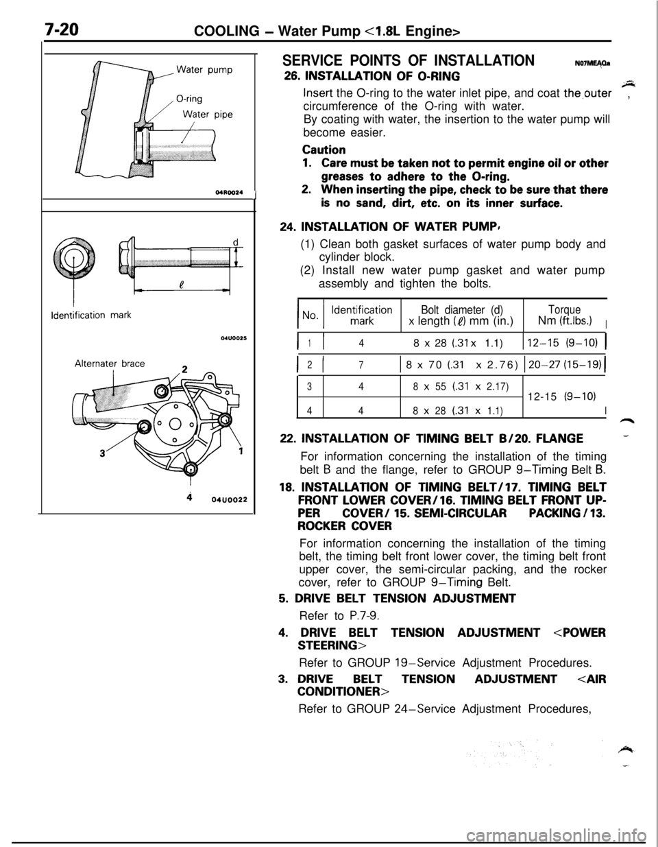
SERVICE POINTS OF INSTALLATIONN07ME40a
26. INSTALLATION OF O-RINGsInsert the O-ring to the water inlet pipe, and coat the,buter
circumference of the O-ring with water.,
By coating with water, the insertion to the water pump will
become easier.
Caution
1.Care must be taken not to permit engine oil or other
greases to adhere to the O-ring.
2.When inserting the pipe, check to be sure,that there
is no sand, dirt, etc. on its inner surface.
24. INSTALLATION OF WATER PUMP,
(1) Clean both gasket surfaces of water pump body and
cylinder block.
(2) Install new water pump gasket and water pump
assembly and tighten the bolts.
Bolt diameter (d)Torque
x length (e) mm (in.)Nm (ftlbs.)I
I I148 x 28 (.31 x 1.1)112-15 (9-10) 1
I I2
71 8 x 70 (.31 x 2.76) 120-27 (15-19)(
348x55(.31x2.17)12-15(9-10)
448x28(.31x1.1)I
22. INSTALLATION OF TIMING BELT B/20. FLANGE-For information concerning the installation of the timing
belt
B and the flange, refer to GROUP g-Timing Belt B.
18. INSTALLATION OF TIMING BELT/l7. TIMING BELT
FRONT LOWER COVER/lG. TIMING BELT FRONT UP-
PERCOVER/ 15. SEMI-CIRCULARPACKING / 13.
ROCKER COVERFor information concerning the installation of the timing
belt, the timing belt front lower cover, the timing belt front
upper cover, the semi-circular packing, and the rocker
cover, refer to GROUP
g-Timing Belt.
5. DRIVE BELT TENSION ADJUSTMENT
Refer to
P.7-9.
4. DRIVE BELT TENSION ADJUSTMENT
Refer to GROUP
19-Service Adjustment Procedures.
3. DRIVEBELTTENSIONADJUSTMENT
Refer to GROUP
24-Service Adjustment Procedures,
Page 269 of 1216
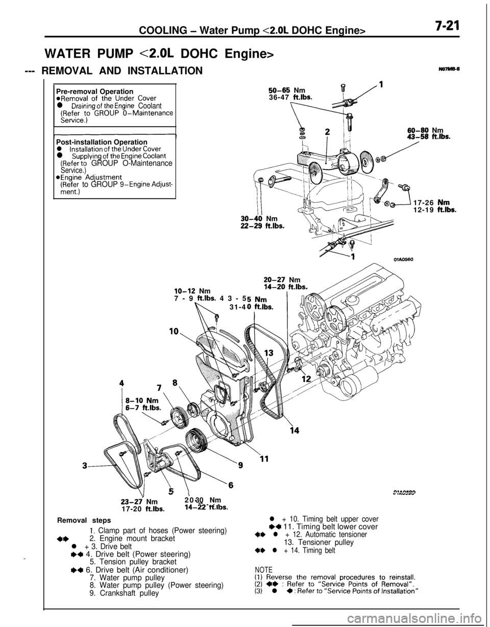
COOLING - Water Pump <2.0L DOHC Engine>7-21WATER PUMP <2.0L DOHC Engine>
--- REMOVAL AND INSTALLATION
No7Ms-B
_Pre-removal Operation
@Removal of the Under Coverl Draining of the Engine Coolant(Refer to GROUP O-MaintenanceService.)
50-65 Nm136-47 ft.lbs.
60-60 Nm
Post-installation Operation
l installation of the Under Coverl supplying of the Engine Coolant(Refer to GROUP O-MaintenanceService.)*Engine Adjustment
(Ri+&; to GROUP g-Engine Adjust-
lo-12 Nm
7-9 ft.lbs. 43-5
31-4
III-40 Nm!-29 ft.lbs.17-26
12-19OlAO560
20-27 Nm14-20 ft.lbs.
23-27 Nm
17-20 ft.lbs.
”20-’ 30 Nm” .““*wY--
-~ . .14-22 ft.ll3s.Removal steps
I. Clamp part of hoses (Power steering)
+*2. Engine mount bracket
l + 3. Drive belte+ 4. Drive belt (Power steering)5. Tension pulley bracket
I)4 6. Drive belt (Air conditioner)7. Water pump pulley
8. Water pump pulley (Power steering)
9. Crankshaft pulley
l + 10. Timing belt upper coverI)4 11. Timing belt lower cover+I) l + 12. Automatic tensioner13. Tensioner pulley
+I) l + 14. Timing belt
NOTE(1) Reverse the removal procedures to reinstall.(2) +e : Refer to “Service Points of Removal”.(3) l 4 : Refer to “Service Points of Installation”
,“k.
Page 270 of 1216
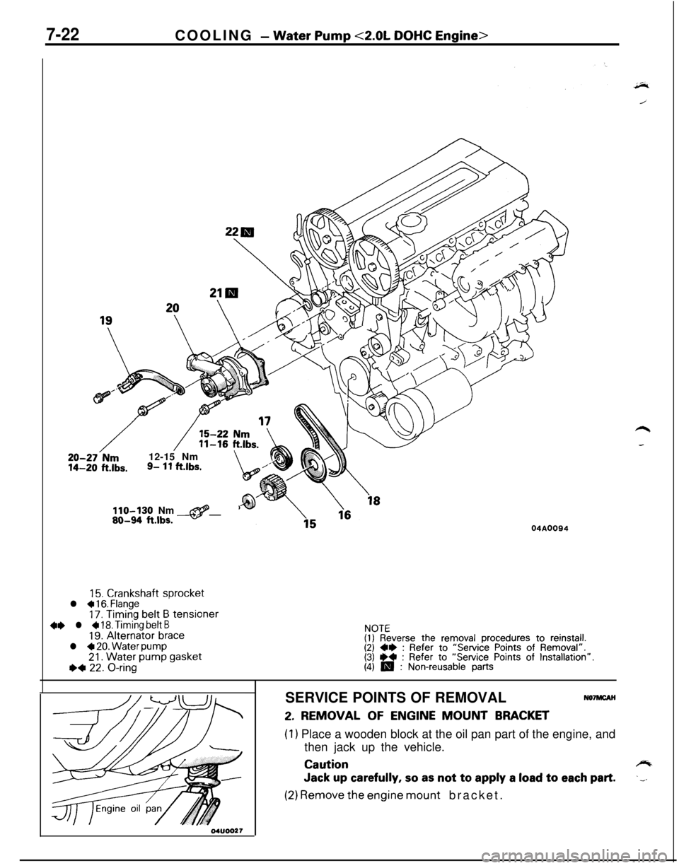
7-22COOLING - Water Pump <2.0L DOHC Engine>
20-27-Nm12-15 Nm14-20 ft.lbs.9- 11 ftlbs.\,/”
110-130 Nm@80-94 ftlbs. -04A0094
15. Crankshaft sprocketl a 16. Flange17. Timing belt B tensioner4e l + 18. Timing belt B19. Alternator bracel 4 20. Water pump21. Water pump gasketI)* 22. O-ring
NOTE(I) Reverse the removal procedures to reinstall.(2) 4* : Refer to “Service Points of Removal”.(3) ** : Refer to “Service Points of Installation”.(4) m : Non-reusable partsSERVICE POINTS OF REMOVAL
NO’IMCAH
2. REMOVAL OF ENGINE MOUNT BRACKET
(1) Place a wooden block at the oil pan part of the engine, and
then jack up the vehicle.
Cautioncylb
Jack up carefully, so as not to apply a load to each part..__
(2) Remove the engine mount bracket.
Page 271 of 1216
COOLING - Water Pump <2.0L DOHC Engine>7-2’3
12. REMOVAL OF AUTOMATIC TENSIONERI14. TIMING
BELTFor information concerning removal of the automatic
tensioner and the timing belt, refer to GROUP
g-Timing
Belt.
18. REMOVAL OF TIMING BELT BFor information concerning the removal of timing belt
6,refer to GROUP
g-Timing Belt B.Quality
canvas
\
\
Core wireAdhesive
rubber
Rib rubberlCOO2I
MRM2.
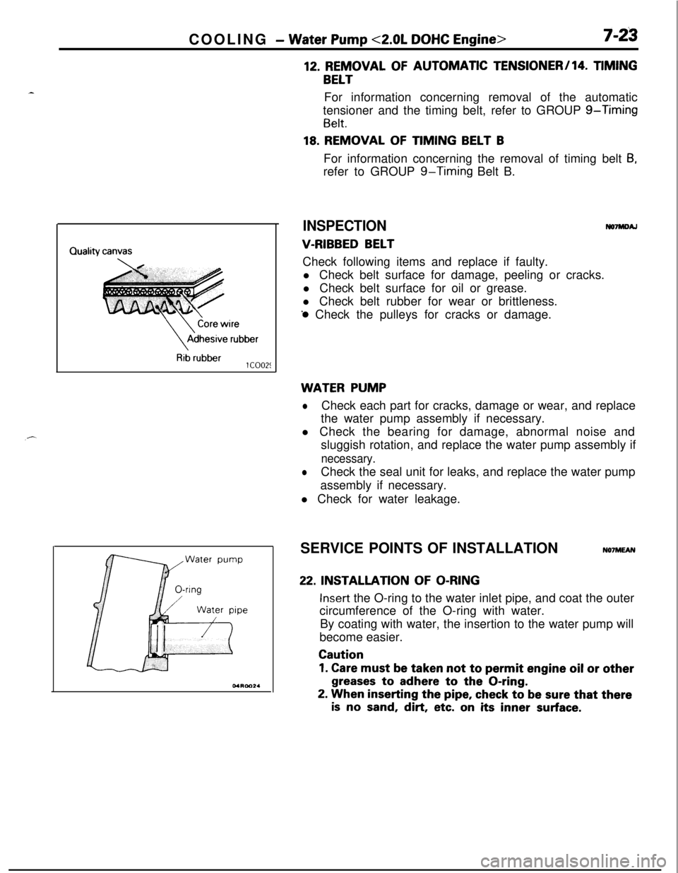
INSPECTION
V-RIBBED BELT
No7mDA.lCheck following items and replace if faulty.
l Check belt surface for damage, peeling or cracks.
l Check belt surface for oil or grease.
l Check belt rubber for wear or brittleness.
‘0 Check the pulleys for cracks or damage.
WATER PUMP
lCheck each part for cracks, damage or wear, and replace
the water pump assembly if necessary.
l Check the bearing for damage, abnormal noise and
sluggish rotation, and replace the water pump assembly if
necessary.
lCheck the seal unit for leaks, and replace the water pump
assembly if necessary.
l Check for water leakage.
SERVICE POINTS OF INSTALLATION
N07MEAN
22. INSTALLATION OF O-RING
Insert the O-ring to the water inlet pipe, and coat the outer
circumference of the O-ring with water.
By coating with water, the insertion to the water pump will
become easier.
Caution
1. Care must be taken not to permit engine oil or other
greases to adhere to the O-ring.
2. When inserting the pipe, check to be sure that there
is no sand, dirt, etc. on its inner surface.
Page 272 of 1216
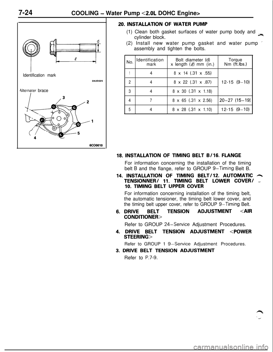
7-24COOLING - Water Pump <2.0L DOHC Engine>
Identification mark
4lternater brace
6COOOlO
20. INSTALLATION OF WATER PUMP
(1) Clean both gasket surfaces of water pump body and
jir,cylinder block.
(2) Install new water pump gasket and water pump ’
assembly and tighten the bolts.
No, IdentificationBolt diameter (d)Torquemarkx length (I?) mm (in.)Nm (ft.lbs.1
148x14(.31x.55)
248x22(.31x.87)12-15(g-10)
348x30(.31x1.18)
4
78x65(.31x2.56)20-27(15-191
548x28(.31x1.10)12-15(g-10)
18. INSTALLATION OF TIMING BELT B/16. FLANGEFor information concerning the installation of the timing
belt
B and the flange, refer to GROUP g-Timing Belt B.
14. INSTALLATION OF TIMING BELT/lZ. AUTOMATIC 6TENSlONNER/
11. TIMING BELT LOWER COVER/ -
10. TIMING BELT UPPER COVERFor information concerning installation of the timing belt,
the automatic tensioner, the timing belt lower cover, and
the timing belt upper cover, refer to GROUP g-Timing Belt.
6. DRIVEBELT TENSIONADJUSTMENT
Refer to GROUP
24-Service Adjustment Procedures.
4. DRIVE BELT TENSION ADJUSTMENT
Refer to GROUP 1
g-Service Adjustment Procedures.
3. DRIVE BELT TENSION ADJUSTMENT
Refer to
P.7-9.
Page 273 of 1216
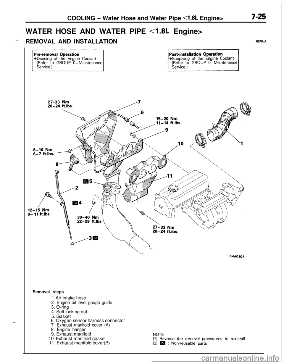
COOLING - Water Hose and Water Pipe <1.8L Engine>
WATER HOSE AND WATER PIPE
<1.8L Engine>
_-REMOVAL AND INSTALLATIONNO’IIA-A27-33 Nm
20-24 ftlbs.
12-15 Nms- 11 ft.lbs.Removal steps
1 Air intake hose
2. Engine oil level gauge guide3. O-ring
4. Self locking nut
5. Gasket
6. Oxygen sensor harness connector
7. Exhaust manifold cover (A)
8. Engine hanger9. Exhaust manifold
IO. Exhaust manifold gasket
11. Exhaust manifold cover(B)NOTE(1) Reverse the removal procedures to reinstall.(2) m : Non-reusable parts