Mpi MITSUBISHI ECLIPSE 1991 Workshop Manual
[x] Cancel search | Manufacturer: MITSUBISHI, Model Year: 1991, Model line: ECLIPSE, Model: MITSUBISHI ECLIPSE 1991Pages: 1216, PDF Size: 67.42 MB
Page 533 of 1216
FUEL SYSTEM - MPI System Inspection <2.0L QOHC Engine>14-79EGR TEMPERATURE SENSOR
N14RCHAaRefer to GROUP 25
- Exhaust Gas Recirculation System.
VEHICLE SPEED SENSOR
Refer to GROUP 8
- Meters and Gauges.
N140EBBaAIR CONDITIONER SWITCH
Nl4QQAEaRefer to GROUP 8
- Column Switch.
POWER STEERING OIL PRESSURE SWITCH
N14RCJBRefer to GROUP 19 for power steering system inspection.
INJECTORS
NWXAHCHECKING OPERATION SOUND
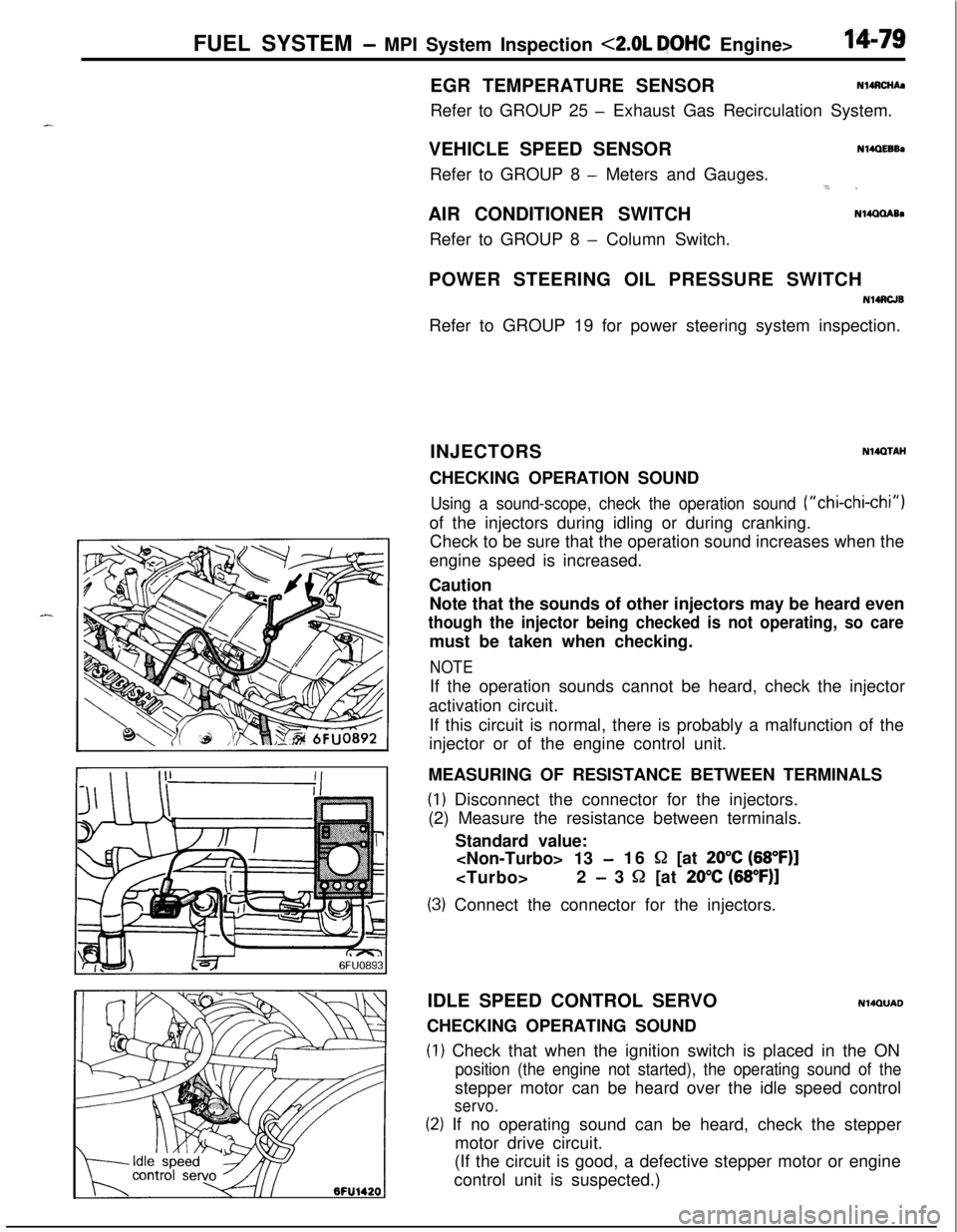
Using a sound-scope, check the operation sound (“chi-chi-chi”)of the injectors during idling or during cranking.
Check to be sure that the operation sound increases when the
engine speed is increased.
Caution
Note that the sounds of other injectors may be heard even
though the injector being checked is not operating, so caremust be taken when checking.
NOTEIf the operation sounds cannot be heard, check the injector
activation circuit.
If this circuit is normal, there is probably a malfunction of the
injector or of the engine control unit.
MEASURING OF RESISTANCE BETWEEN TERMINALS
(1) Disconnect the connector for the injectors.
(2) Measure the resistance between terminals.
Standard value:
-16 S2 [at 20°C (68”F)]
- 3 52 [at 20% (68”F)]
(3) Connect the connector for the injectors.
IDLE SPEED CONTROL SERVO
N14QUADCHECKING OPERATING SOUND
(1) Check that when the ignition switch is placed in the ON
position (the engine not started), the operating sound of thestepper motor can be heard over the idle speed control
servo.
(2) If no operating sound can be heard, check the stepper
motor drive circuit.
(If the circuit is good, a defective stepper motor or engine
control unit is suspected.)
Page 534 of 1216
14-80FUEL SYSTEM - MPI System Inspection <2.0L DOHC Enginh
7FUOOlO6FU1426
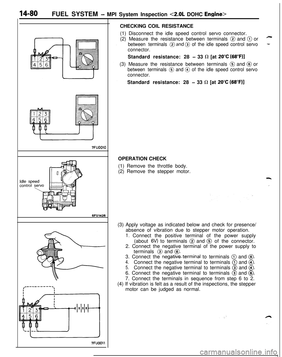
7FUOOllCHECKING COIL RESISTANCE
(1) Disconnect the idle speed control servo connector.
(2) Measure the resistance between terminals
@ and @ or
between terminals @and @ of the idle speed control servo
connector.Standard resistance: 28
- 33 fl [at 20°C (68”F)l(3) Measure the resistance between terminals
@ and @ or
between terminals @ and @ of the idle speed control servo
connector.Standard resistance: 28
- 33 LR [at 20°C (68”F)]OPERATION CHECK
(1) Remove the throttle body.
(2) Remove the stepper motor.
(3) Apply voltage as indicated below and check for presence/
absence of vibration due to stepper motor operation.
1. Connect the positive terminal of the power supply
(about
6V) to terminals @ and @ of the connector.
2. Connect the negative terminal of the power supply to
terminals @ and
@.3. Connect the negativeterminal to terminals
@ and @.
4.Connect the negative terminal to terminals @ and @.
5.Connect the negative terminal to terminals @ and @.6. Connect the negative terminal to terminals
@ and @.7. Connect the terminals in sequence from step 6 to 2.
(4) If vibration is felt as a result of the inspections, the stepper
motor can be judged as normal.
Page 535 of 1216
_-
FUEL SYSTEM - MPI System Inspection <2.0L DOHC Engine>'I4181
OlLO22Z
CONTROL RELAY
INSPECTIONNWWAC
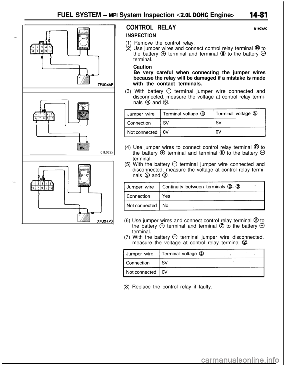
(1) Remove the control relay.
(2) Use jumper wires and connect control relay terminal
@I to
the battery
@ terminal and terminal @ to the battery 0
terminal.Caution
Be very careful when connecting the jumper wires
because the relay will be damaged if a mistake is made
with the contact terminals.
(3) With battery
0 terminal jumper wire connected and
disconnected, measure the voltage at control relay termi-
nals
@I and 0.(4) Use jumper wires to connect control relay terminal
@ to
the battery
@ terminal and terminal @ to the battery 0
terminal.(5) With the battery
@ terminal jumper wire connected and
disconnected, measure the voltage at control relay termi-
nals
@I and 0.
Continuity between terminals 0-0
)(6) Use jumper wires and connect control relay terminal
@ to
the battery
@ terminal and terminal @ to the battery 0
terminal.(7) With the battery
0 terminal jumper wire disconnected,
measure the voltage at control relay terminal
0.
31(8) Replace the control relay if faulty.
Page 536 of 1216
14-82FUEL SYSTEM - MPI System Inspection <2.0L DOHC Engine>
\ \\I \3FUO352
,\ \
\I \3FUO353
,\ ‘\R/
\ \\I \3FUo354
POWER TRANSISTORRefer to GROUP 8
- Ignition System
NlIAcQAl
a-4
AIR CONDITIONER POWER RELAYN14NCl.a -Refer to GROUP 24
- Air Conditioner.
PURGE CONTROL SOLENOID VALVEN14RCKARefer to GROUP 25
- Evaporative Emission Control System.
EGR CONTROL SOLENOID VALVE
N14NCURefer to GROUP 25
- Exhaust Gas Recirculation System.
FUEL PRESSURE CONTROL VALVE
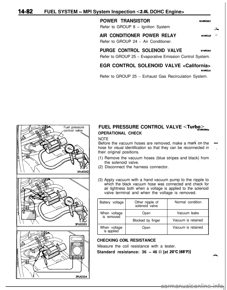
NOTEBefore the vacuum hoses are removed, make a mark’on the
-
hose for visual identification so that they can be reconnected in,their original positions.
(1) Remove the vacuum hoses (blue stripes and black) from
the solenoid valve.
(2) Disconnect the harness connector.
(3) Apply vacuum with a hand vacuum pump to the nipple to
which the black vacuum hose was connected and check for
air tightness both when a voltage is applied to the solenoidvalve terminal and when the voltage is removed.
Battery voltageOther nipple of
solenoid valveNormal condition
When voltage
is removed
When voltage
is applied
OpenVacuum leaks
Blocked by fingerVacuum is retained
OpenVacuum is retainedCHECKING
COIL RESISTANCE
Measure the coil resistance with a tester.
Standard resistance: 36
- 46 R [at 20°C (68”F)]
Page 574 of 1216
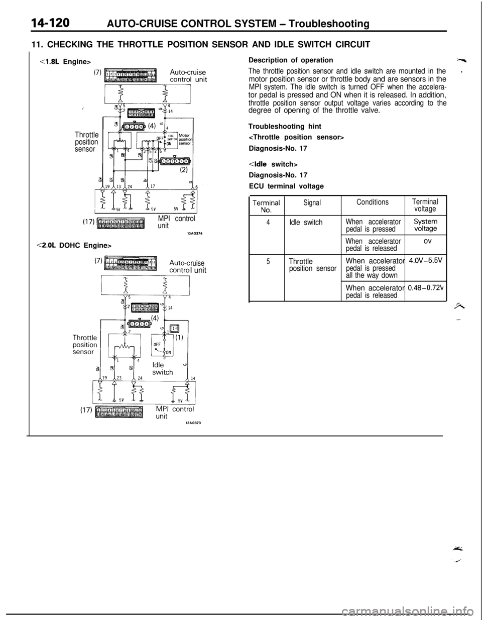
14-120AUTO-CRUISE CONTROL SYSTEM - Troubleshooting
11. CHECKING THE THROTTLE POSITION SENSOR AND IDLE SWITCH CIRCUIT<1.8L Engine>
Throttle
position
sensor
MPI controlunitnw374<2.0L DOHC Engine>
ruiseI unitDescription of operation
“s
The throttle position sensor and idle switch are mounted in the,
motor position sensor or throttle body and are sensors in theMPI system. The idle switch is turned OFF when the accelera-
tor pedal is pressed and ON when it is released. In addition,
throttle position sensor output voltage varies according to thedegree of opening of the throttle valve.Troubleshooting hint
Diagnosis-No. 17
Diagnosis-No. 17
ECU terminal voltageTeKlna’
SignalConditionsTerminal
voltage
4Idle switchWhen accelerator
pedal is pressedXFgr
When acceleratorovpedal is released
5ThrottleWhen accelerator 4.OV-5.5V
position sensorpedal is pressedall the way down
When accelerator 0.48-0.72Vpedal is released
Page 579 of 1216
AUTO-CRUISE CONTROL SYSTEM - Troubleshooting
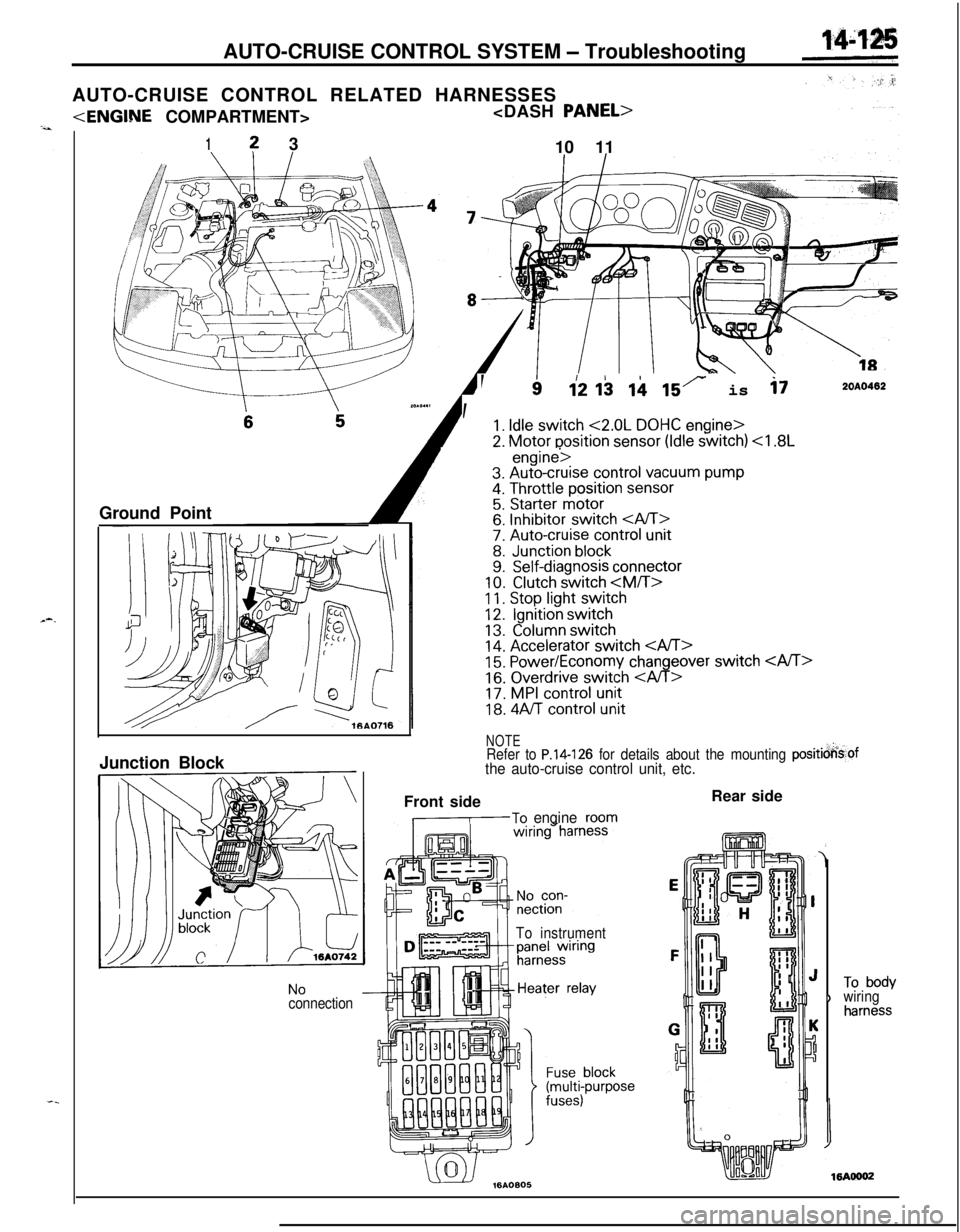
AUTO-CRUISE CONTROL RELATED HARNESSES
1? 3
10 11
Ground Point
--
, ’
112 I$ ii 15r is i72OAO402
1. Idle switch <2.0L DOHC engine>
2. Motor position sensor (Idle switch)
11. Stop light switch12.Ignition switch
13.Column switch14. Accelerator switch 15. Power/Economy changeover switch
16. Overdrive switch
18. 4Aff control unit
NOTERefer to P.14-126 for details about the mounting positicjkof
the auto-cruise control unit, etc.Junction Block
NoconnectionFront side
,-To engineroom
To instrumentRear side
)To bodywiringharness
Page 580 of 1216
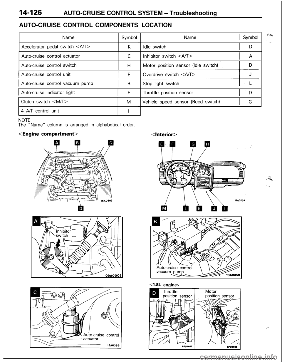
14-126AUTO-CRUISE CONTROL SYSTEM - Troubleshooting
AUTO-CRUISE CONTROL COMPONENTS
Name
Accelerator pedal switch
Symbol
K
Auto-cruise control actuator
Auto-cruise control switch
C
H
IAuto-cruise control unitIE
IAuto-cruise control vacuum pumpIB
IAuto-cruise indicator lightIF
Clutch switch
4 A/T control unit
M
I
NOTE
The “Name” column is arranged in alphabetical order.
LOCATION
1 Symbol
Idle switchIDInhibitor switch
Motor position
sensor (Idle switch)
ziz&Gy+Throttle position
sensor
Vehicle speed sensor (Reed switch)IG
Motor1position sensor
I.F”l.O,VUUW
Page 584 of 1216
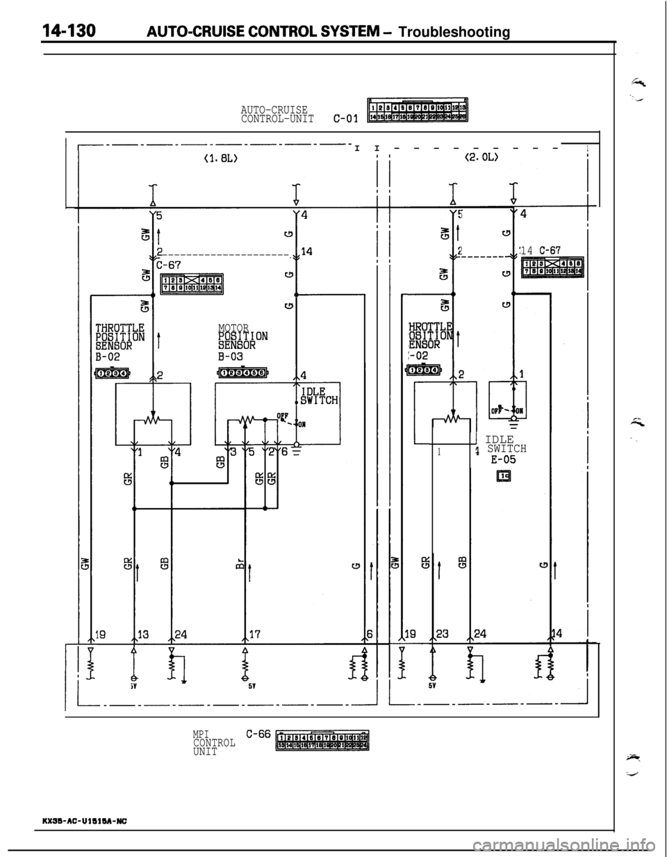
14-130AUTO-CRUISE CONTROL SYSTEM - Troubleshooting
AUTO-CRUISE
CONTROL-UNITc-01
1 I_-_-_-_-_-_-__II---------lI
i
t
---------------------C-67s
I I
I II I
%Ic!Y
MOTOR;iW'O;;ON
B-03
5
8t
2
i
r!
__------
5c!
ec!
14 C-67
rHROTTLE;gj&ON
t
3-02
19
r
!4
L
%iV
1 IDLE1 SWITCH
E-051
MPICONTROLC-66
UNIT
KXW-AC-UllllM-NC
Page 587 of 1216
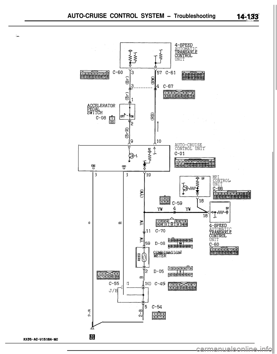
AUTO-CRUISE CONTROL SYSTEM - Troubleshooting1:4;;1$~”
*,,,’
4-SPEED
AUTOMATIC
;&V&'~;LE
UNIT
--------
JF
rAUTO-CRUISEY5v 9CONTROL UNIT
GNI"
4clmc-55
,J/B
'
r10 c-45=I75 c-54
7
‘pcu1234
m667.3
GNDn
MPICONTROL
UNIT
C-66
4-SPEED
AUTOMATIC
-&$$$)ELE
UNIT
C-60
COMBINATIONKXJS-AC-UlSlBh-NC
El
Page 588 of 1216
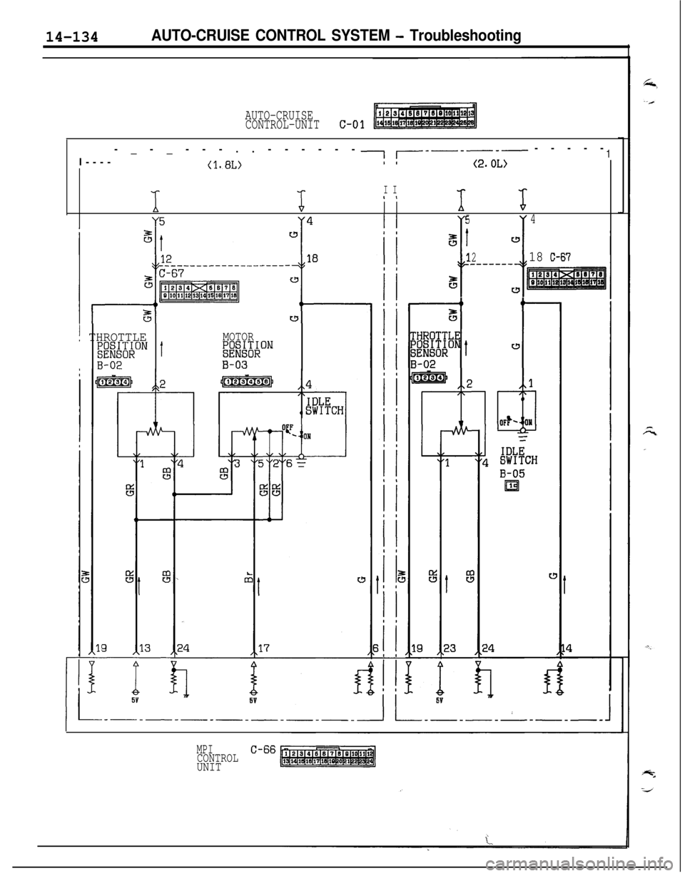
14-134AUTO-CRUISE CONTROL SYSTEM - Troubleshooting
AUTO-CRUISE
CONTROL-UNITc-01I-----_-_---..------
II------ -----1
(l.BL)(2.0L)1
‘6
I II I
‘h‘s
Y5Y4
"
54
5Iw
I I
1218 C-67_------
eww
16
-L
w
w
! THROTTLE;g;E&ONt
B-02
MOTOR;;iEX;&ON
B-03
MPICONTROLC-66
UNIT