Mpi MITSUBISHI ECLIPSE 1991 Repair Manual
[x] Cancel search | Manufacturer: MITSUBISHI, Model Year: 1991, Model line: ECLIPSE, Model: MITSUBISHI ECLIPSE 1991Pages: 1216, PDF Size: 67.42 MB
Page 612 of 1216
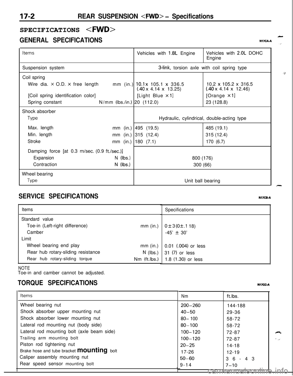
17-2REAR SUSPENSION
GENERAL SPECIFICATIONS
LN17CAA
ItemsVehicles with 1.8L EngineVehicles with 2.0L DOHC
Engine
jSuspension system
3-link, torsion axle with coil spring type
Coil spring
Wire dia.
x O.D. x free length
mm (in.) 10.1 x 105.1 x 336.510.2 x 105.2 x 316.5
(40 x 4.14 x 13.25)(40 x 4.14 x 12.46)
[Coil spring identification color]
[Light Blue
x 11[Orange x 11Spring constant
N/mm
(Ibs./in.) 20 (112.0)23 (128.8)
Shock absorber
TypeHydraulic, cylindrical, double-acting type
Max. length
mm (in.) 495 (19.5)485 (19.1)
Min. length
mm (in.) 315 (12.4)315 (12.4)
Strokemm (in.) 180 (7.1)170 (6.7)Damping force [at 0.3 m/set. (0.9
ft./set.)]
ExpansionN (Ibs.)800 (176)
ContractionN (Ibs.)300 (66)
Wheel bearing
TypeUnit ball bearing
SERVICE SPECIFICATIONS
Items
Standard valueToe-in (Left-right difference)
Camber
LimitWheel bearing end play
Rear hub rotary-sliding resistance
Rear hub rotary-sliding torque
NOTEToe-in and camber cannot be adjusted.mm (in.)
mm (in.)
N (Ibs.)
Nm
(ftlbs.)
TORQUE SPECIFICATIONS
Specifications
0+3 (Of.1 18)
-45’
f 30’
0.01 (004) or less
31
(7) or less
1.8
(1.30) or lessNI’ICB-A
ItemsNmft.lbs.
Wheel bearing nut
Shock absorber upper mounting nut
Shock absorber lower mounting nut
Lateral rod mounting nut (body side)
Lateral rod mounting bolt (axle beam side)
Trailing arm mounting bolt
Piston rod tightening nut
Brake hose and tube bracket mounting bolt
Caliper assembly mounting nut
Rear speed sensor mounting bolt
200-260
40-50
80- 100
80-100
100-120
100-120
20-2517-26
50-609-14144-188
29-36
58-72
58-72
72-87
72-87
14-18
12-19
36-43
I7-10
Nl7CGA
Page 626 of 1216

17-16REAR SUSPENSION
SPECIFICATIONS
GENERAL SPECIFICATIONSNl’ICA-B jG
ItemsSpecifications
Suspension systemDouble wishbone suspension type
Coil spring
Wire dia. x O.D.
x free lengthmm (in.)11.0 x 106.0 x 332.5 (.43 x 4.17 x 13.1)Coil spring identification colorPurple
x 1Spring constantN/mm
(Ibs./in.) 25.0 (140)
Shock absorber
TypeHydraulic, cylindrical, double-acting type
Max. lengthmm (in.) 568
(22.4)Min. lengthmm (in.) 380
(15.0)
Strokemm (in.) 188 (7.4)
Damping force [at 0.3 m/set. (0.9
ft./set.)]
ExpansionN (Ibs.) 900 (198)
ContractionN (Ibs.) 300 (66)
SERVICE SPECIFICATIONS
Items
Standard value
Toe-in
CamberSpecificationsmm (in.) 3.6+3 (.14f.l18)
-1"33'f30'
Nl7CEB
:&
Page 901 of 1216
AUTOMATIC TRANSAXLE - Troubleshooting21-207
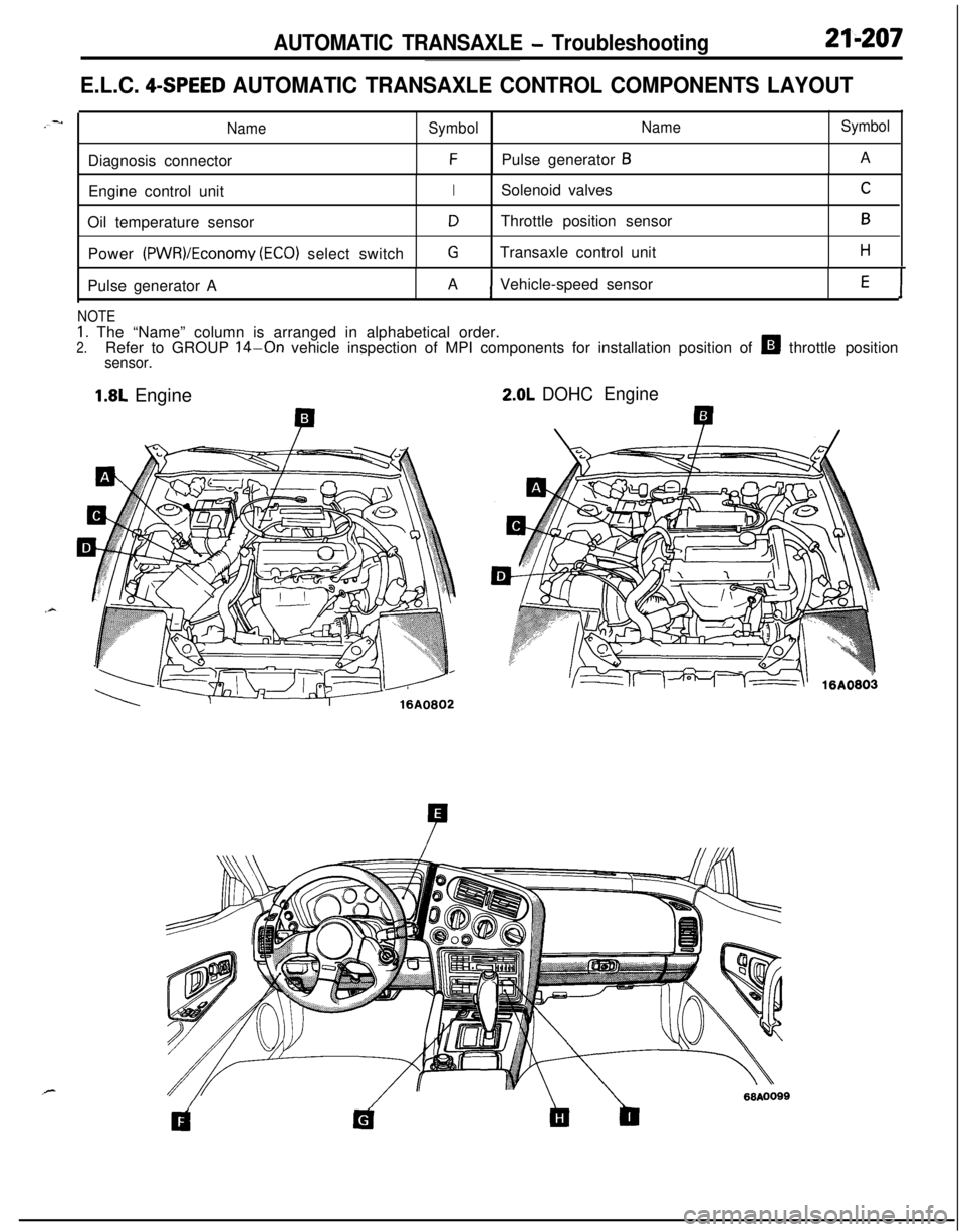
E.L.C. 4-SPEED AUTOMATIC TRANSAXLE CONTROL COMPONENTS LAYOUT
NameSymbolNameSymbolDiagnosis connector
FPulse generator BA
Engine control unit
ISolenoid valvesCOil temperature sensor
DThrottle position sensorBPower
(PWR)/Economy (ECO) select switchGTransaxle control unitHPulse generator AAVehicle-speed sensor
E1
NOTE
1. The “Name” column is arranged in alphabetical order.2.Refer to GROUP 14-On vehicle inspection of MPI components for installation position of H throttle positionsensor.
1.8L Engine2.0L DOHCEngine
Page 1149 of 1216
HEATERS AND AIR CONDITIONING - Troubleshooting24-5
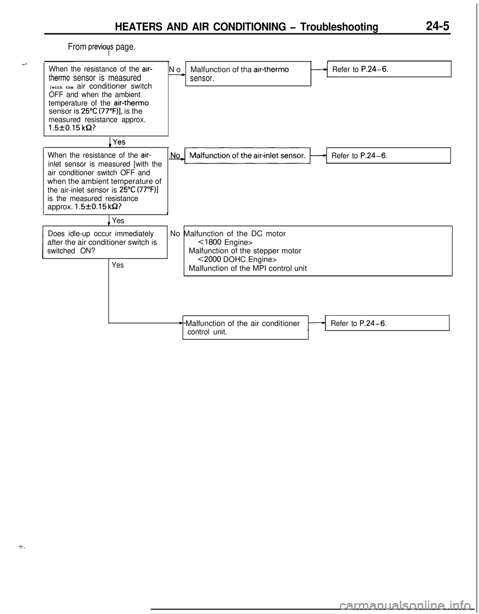
From previoys page.
When the resistance of the air-
therm0 sensor is measured[with the air conditioner switch
OFF and when the ambient
temperature of the
air-therm0sensor is
25°C (77“F)], is the
measured resistance approx.
1.5f0.15 kP?
INoMalfunction of tha air-therm0Refer to P.24-6.-sensor.
Refer to P.24-6.
1Yes
When the resistance of the air-
inlet sensor is measured [with the
air conditioner switch OFF andwhen the ambient temperature of
the air-inlet sensor is 25°C (77”F)l
is the measured resistanceapprox.
1.5f0.15 k&2?I
1 Yes
Does idle-up occur immediatelyNo Malfunction of the DC motor
after the air conditioner switch is
cl800 Engine>
switched ON?Malfunction of the stepper motor
Yes~2000 DOHC Engine>
Malfunction of the MPI control unit
* Malfunction of the air conditioner
control unit.Refer to P.24-6.
Page 1150 of 1216
24-6HEATERS AND AIR CONDITIONING - TroubleshootingAIR CONDITIONER CONTROL
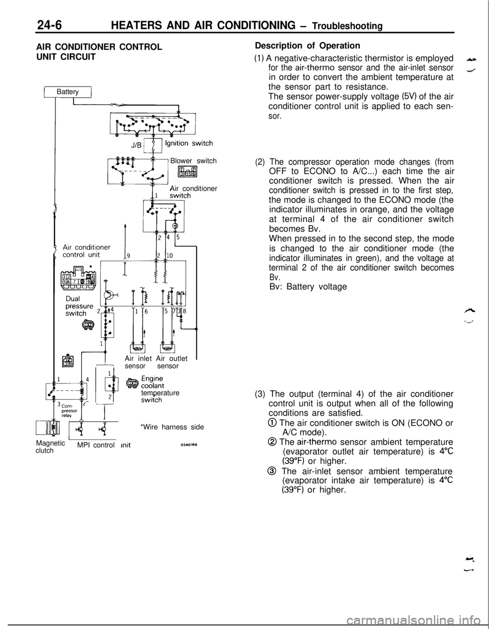
UNIT CIRCUIT
1 Battery IBlower switch
litalAir conditioner
IAir inlet Air outlet1-isensorsensor
temperature
Corn- L Tpressor
relayI IMagnetic
AclutchMPI control*Wire harness sideDescription of Operation
(1) A negative-characteristic thermistor is employed
for the air-therm0 sensor and the air-inlet sensorin order to convert the ambient temperature at
the sensor part to resistance.
The sensor power-supply voltage
(5V) of the air
conditioner control unit is applied to each sen-
sor.
(2) The compressor operation mode changes (fromOFF to ECONO to A/C...) each time the air
conditioner switch is pressed. When the air
conditioner switch is pressed in to the first step,the mode is changed to the ECONO mode (the
indicator illuminates in orange, and the voltage
at terminal 4 of the air conditioner switch
becomes Bv.
When pressed in to the second step, the mode
is changed to the air conditioner mode (the
indicator illuminates in green), and the voltage at
terminal 2 of the air conditioner switch becomes
Bv.Bv: Battery voltage
(3) The output (terminal 4) of the air conditioner
control unit is output when all of the following
conditions are satisfied.
@ The air conditioner switch is ON (ECONO or
A/C mode).
@ The air-therm0 sensor ambient temperature
(evaporator outlet air temperature) is
4°C
(39°F) or higher.
@ The air-inlet sensor ambient temperature
(evaporator intake air temperature) is
4°C
(39°F) or higher.
Page 1187 of 1216
HEATERS AND AIR CONDITIONING - Compiessor24-43
2OW660
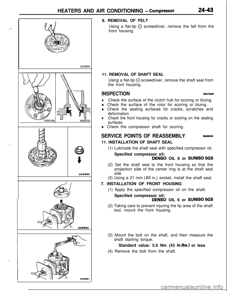
2OW8628. REMOVAL OF FELT
Using a flat-tip
0 screwdriver, remove the felt from the
front housing.
11. REMOVAL OF SHAFT SEAL
Using a flat-tip
0 screwdriver, remove the shaft seal from
the front housing.
INSPECTIONN24TGAH
lCheck the surface of the clutch hub for scoring or bluing.
l Check the surface of the rotor for scoring or bluing.
l Check the sealing surfaces for cracks, scratches and
deformation.
lCheck the front housing for cracks or scoring on the sealing
surfaces.l Check the compressor shaft for scoring.
SERVICE POINTS OF REASSEMBLYN24StiAC11. INSTALLATION OF SHAFT SEAL
(1) Lubricate the shaft seal with specified compressor oil.
Specified compressor oil:
DENS0 OIL 6 or SUNISO 5GS(2) Set the shaft seal to the front housing so that the
projection side of the center ring is at the shaft seal
side.(3) Using a 21 mm
(.83 in,) socket, install the shaft seal.
7. INSTALLATION OF FRONT HOUSING
(1) Apply the specified compressor oil on the shaft.
Specified compressor oil:
DENS0 OIL 6 or SUNISO 5GS(2) Taking care to prevent injuring the lip area of the shaft
tool, mount the front housing.
(3) Mount the bolt on the shaft, and then measure the
shaft starting torque.
Standard value: 5.0 Nm (43
in.lbs.) or less
(4) Remove the bolt from the shaft.
Page 1191 of 1216
HEATERS AND AIR CONDITIONING - Refrigerant Line24-47
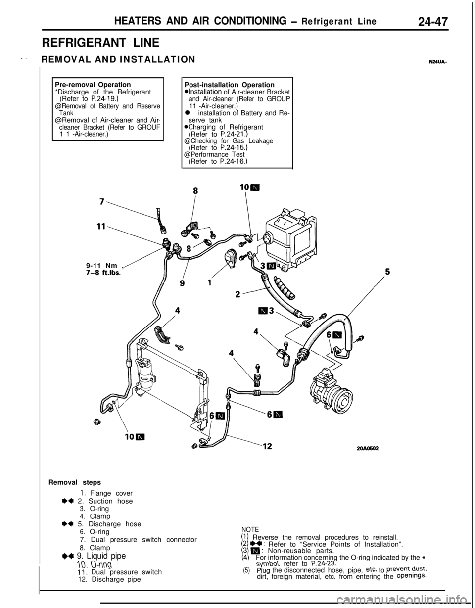
REFRIGERANT LINE
- -REMOVAL AND INSTALLATIONN24UA-Pre-removal Operation
*Discharge of theRefrigerant
(Refer to
P.24-19.)@Removal of Battery and ReserveTank@Removal of Air-cleaner and Aircleaner Bracket (Refer to GROUF
1 1 -Air-cleaner.)Post-installation Operation
@Installation of Air-cleaner Bracketand Air-cleaner (Refer to GROUP11 -Air-cleaner.)
l installation of Battery and Re-
serve tank
Kharging of Refrigerant
(Refer to P.24-21.)@Checking for Gas(Refer to P.24-15.)Leakage
@Performance Test(Refer to
P.24-16.)9-11 Nm ,
7-8 ft.lbs.
20AO502Removal steps
I. Flange cover
I)+ 2. Suction hose3.O-ring
4.ClampI)* 5. Discharge hose6.O-ring
7. Dual pressure switch connector
8.Clamp
e+ 9. Liquid pipe
10.O-ring11, Dual pressure switch12.Dischargepipe
NOTE(1) Reverse the removal procedures to reinstall.(2) I)4 : Refer to “Service Points of Installation”.(3) N : Non-reusable parts.(4)For information concerning the O-ring indicated by the *symbo\. refer to P.24.23.(5)plug the disconnected hose, pipe, etc, to Prevent dust.dirt, foreign material, etc. from entering the Openings.
Page 1197 of 1216
.^
EMISSION CONTROL
SYSTEMS
CONTENTSN25AA-
CATALYTICCONVERTER...............................20CRANKCASE EMISSION CONTROL
SYSTEM...........................................................7Components Location
...................................7Crankcase Ventilation System
Inspection......................................................8Positive Crankcase Ventilation Valve
...........8EVAPORATIVE EMISSION CONTROL
SYSTEM...........................................................9
AirConditionerSwitch.................................14Air Flow Sensor, Engine Coolant
Temperature Sensor and Intake Air
Temperature Sensor
.....................................14
Canister.........................................................14Components Location
...................................9
FuelFillerCapInspection............................14Overfill Limiter (Two-way Valve)
..................14
PurgeControlSolenoidValve......................13Purge Control
SystemInspection................11
PurgeControlValve
SYSTEM...........................................................15Air-fuel Ratio Control (MPI) System
............20Components Location
...................................15EGR Control Solenoid Valve
.................................................19
EGR
SystemInspection...............................17EGR Temperature Sensor
......19
EGR Valve.....................................................18
Therm0 Valve
SPECIFICATIONS.............................................2General Specifications
..................................2
Sealant..........................................................2Service Specifications
...................................2
TorqueSpecifications...................................2
TROUBLESHOOTING......................................3
VACUUMHOSES...........................................4
VacuumHosesRouting...............................4
Page 1210 of 1216
![MITSUBISHI ECLIPSE 1991 Repair Manual 25-14EMISSION CONTROL SYSTEMS- Evaporative Emission Control System
(5) Measure the resistance between the terminals of the
solenoid valve.
Standard value: 36-44
Q [at 20°C (68OF)]_
6EM137
AIR FLOW S MITSUBISHI ECLIPSE 1991 Repair Manual 25-14EMISSION CONTROL SYSTEMS- Evaporative Emission Control System
(5) Measure the resistance between the terminals of the
solenoid valve.
Standard value: 36-44
Q [at 20°C (68OF)]_
6EM137
AIR FLOW S](/img/19/57104/w960_57104-1209.png)
25-14EMISSION CONTROL SYSTEMS- Evaporative Emission Control System
(5) Measure the resistance between the terminals of the
solenoid valve.
Standard value: 36-44
Q [at 20°C (68OF)]_
6EM137
AIR FLOW SENSOR, ENGINE COOLANT TEMPER-
ATURE SENSOR AND INTAKE AIR TEMPERA-
TURE SENSORTo inspect these parts, refer to GROUP
14-MPI System
Components.‘.
AIR CONDITIONER SWITCHTo inspect the air conditioner switch, refer to GROUP
24’--AirConditioner Switch.
OVERFILL LIMITER (TWO-WAY VALVE)N2BlBE&To inspect the overfill limiter (two-way valve), refer to GROUP
14-Fuel Tank.
CANISTERNzslBmTo inspect the canister, refer to GROUP
14-Fuel Line and
Vapor Line.
FUEL FILLER CAP INSPECTIONNZSIBJACheck the gasket of the fuel filler cap, and, the filler cap itself,
for damage or deformation; replace the cap if necessary.
Page 1216 of 1216
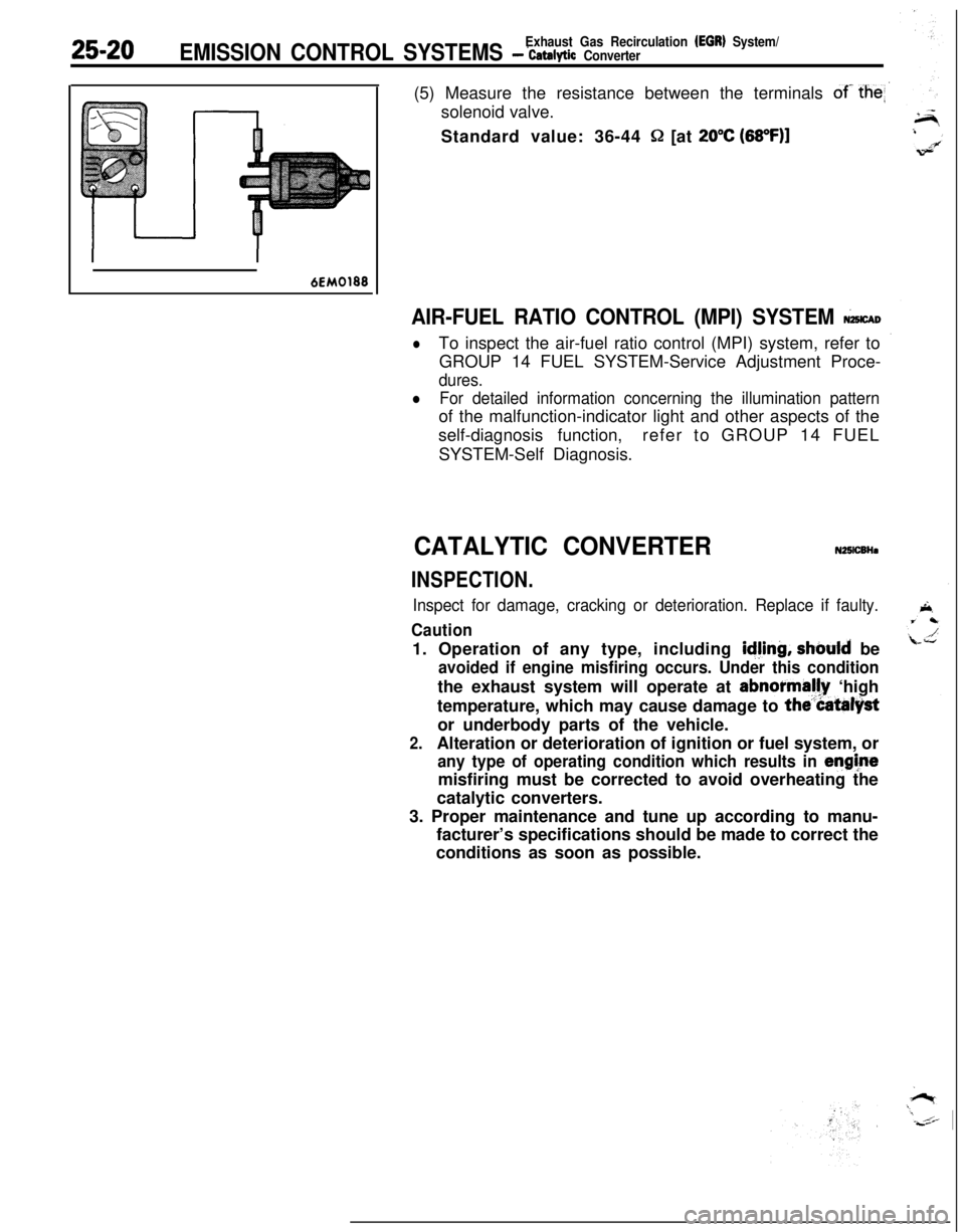
25-20Exhaust Gas Recirculation (EGR) System/EMISSION CONTROL SYSTEMS - ‘catalytic Converter(5) Measure the resistance between the terminals
of- the
Q [at 20°C (68OF)l
6EM0188
AIR-FUEL RATIO CONTROL (MPI) SYSTEM &CAD
lTo inspect the air-fuel ratio control (MPI) system, refer to
GROUP 14 FUEL SYSTEM-Service Adjustment Proce-
dures.
lFor detailed information concerning the illumination patternof the malfunction-indicator light and other aspects of the
self-diagnosis function,refer to GROUP 14 FUEL
SYSTEM-Self Diagnosis.
CATALYTIC CONVERTERN25lCBHa
INSPECTION.
Inspect for damage, cracking or deterioration. Replace if faulty.
Caution1. Operation of any type, including
idjing, should be
avoided if engine misfiring occurs. Under this conditionthe exhaust system will operate at abnormally ‘high
temperature, which may cause damage to
the”Catalystor underbody parts of the vehicle.
2.Alteration or deterioration of ignition or fuel system, or
any type of operating condition which results in enghtemisfiring must be corrected to avoid overheating the
catalytic converters.
3. Proper maintenance and tune up according to manu-
facturer’s specifications should be made to correct the
conditions as soon as possible.