checking oil MITSUBISHI ECLIPSE 1991 Service Manual
[x] Cancel search | Manufacturer: MITSUBISHI, Model Year: 1991, Model line: ECLIPSE, Model: MITSUBISHI ECLIPSE 1991Pages: 1216, PDF Size: 67.42 MB
Page 13 of 1216
INTRODUCTION AND MASTER TROUBLESHOOTING - Precautions befdre Service‘1 S
OOV663OOY192
FOOO 1.
FOOO18
0
OOD511
J7
PRECAUTIONS BEFORE SERVICE wxww
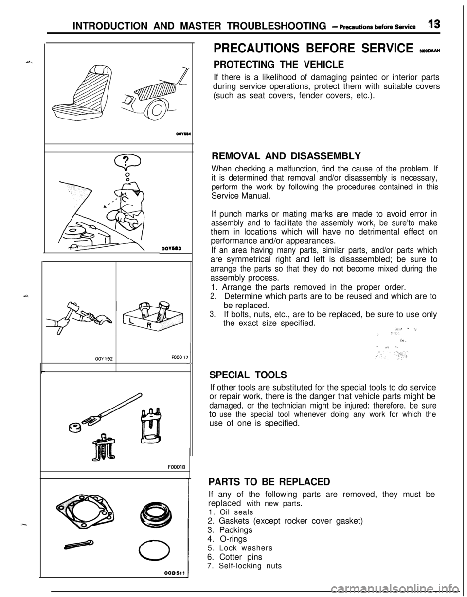
PROTECTING THE VEHICLEIf there is a likelihood of damaging painted or interior parts
during service operations, protect them with suitable covers
(such as seat covers, fender covers, etc.).
REMOVAL AND DISASSEMBLY
When checking a malfunction, find the cause of the problem. If
it is determined that removal and/or disassembly is necessary,
perform the work by following the procedures contained in thisService Manual.
If punch marks or mating marks are made to avoid error in
assembly and to facilitate the assembly work, be sure’to makethem in locations which will have no detrimental effect on
performance and/or appearances.
If an area having many parts, similar parts, and/or parts whichare symmetrical right and left is disassembled; be sure to
arrange the parts so that they do not become mixed during theassembly process.
1. Arrange the parts removed in the proper order.
2.Determine which parts are to be reused and which are to
be replaced.
3.If bolts, nuts, etc., are to be replaced, be sure to use only
the exact size specified.
i:c ” -,.> ‘..“i,. i” ,,‘. 5,
SPECIAL TOOLSIf other tools are substituted for the special tools to do service
or repair work, there is the danger that vehicle parts might be
damaged, or the technician might be injured; therefore, be sureto use the special tool whenever doing any work for which the
use of one is specified.
PARTS TO BE REPLACEDIf any of the following parts are removed, they must be
replaced with new parts.
1. Oil seals
2. Gaskets (except rocker cover gasket)
3. Packings
4. O-rings
5. Lock washers
6. Cotter pins
7. Self-locking nuts
Page 129 of 1216
REAR AXLE - Differential Carrier3-27
llK010
71
llY181llY182
.MB990836(MB990835)
llrm3
V223
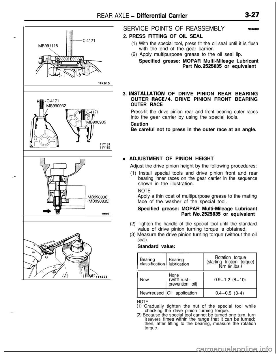
SERVICE POINTS OF REASSEMBLYNOJUBD2. PRESS FITTING OF OIL SEAL
(1) With the special tool, press fit the oil seal until it is flushwith the end of the gear carrier.
(2) Apply multipurpose grease to the oil seal lip.
Specified grease: MOPAR Multi-Mileage Lubricant
Part No.2525035 or equivalent
3. lNSTALLATlON OF DRIVE PINION REAR BEARING
OUTER RACE/4. DRIVE PINION FRONT BEARING
OUTER RACE
Press-fit the drive pinion rear and front bearing outer racesinto the gear carrier by using the special tools.
CautionBe careful not to press in the outer race at an angle.
l ADJUSTMENT OF PINION HEIGHT
Adjust the drive pinion height by the following procedures:
(1) Install special tools and drive pinion front and rear
bearing inner races on the gear carrier in the sequenceshown in the illustration.
NOTEApply a thin coat of multipurpose grease to the mating
face of the washer of the special tool.
Specified grease: MOPAR Multi-Mileage Lubricant
Part No.2525035 or equivalent
(2) Tighten the handle of the special tool until the standardvalue of drive pinion turning torque is obtained.
(3) Measure the drive pinion turning torque (without the oil
seal).Standard value:
Rotation torque
(starting friction torque)Nm
(in.lbs.)
I
NoneNew(with rust-I0.9-1.2 (8-10)prevention oil)New/reused Oil application
NOTE
0.4-0.5 (3-4)(I) Gradually tighten the nut of the special tool while
checking the drive pinion turning torque.
(2) Because the special tool cannot be turned one turn, turnit several times within the range that it can be turned;then, after fitting to the bearing, measure the rotation
torque.
Page 136 of 1216
3-34REAR AXLE - Differential Carrier (Limited Slip Differential)
DIFFERENTIAL CARRIER (LIMITED SLIP DIFFERENTIAL)
DISASSEMBLY AND REASSEMBLYNO31K--
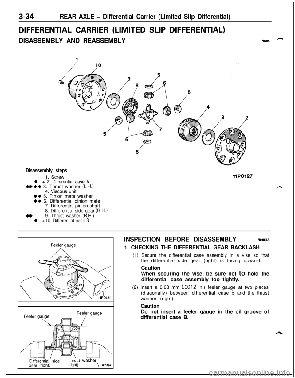
Disassembly steps
1. Screwl + 2. Differential case A+e I)+ 3. Thrust washer (L.H.)4. Viscous unit
llP0127
I)+ 5. Pinion mate washer
M 6. Differential pinion mate
7. Differential pinion shaft
8. Differential side gear
(R.H.)
4+9. Thrust washer (R.H.)
l +
10. Differential case 6Feeler gauge-eeler gauge
\Feeler gauge/
’ IL4l\’IIDifferential sideThrkt washer
aear (riaht)(right)\llPO139
INSPECTION BEFORE DISASSEMBLYNO3IEBA1. CHECKING THE DIFFERENTIAL GEAR BACKLASH
(1) Secure the differential case assembly in a vise so that
the differential side gear (right) is facing upward.
Caution
When securing the vise, be sure not to hold the
differential case assembly too tightly.
(2) Insert a 0.03 mm (.0012 in.) feeler gauge at two places
(diagonally) between differential case
B and the thrust
washer (right).
CautionDo not insert a feeler gauge in the oil groove of
differential case B.
Page 260 of 1216
7-12COOLING - Radiator
RADIATORPre-removal Operation
@Draining of the Engine Coolant(Refer to GROUP O-Maintenance(Refer to GROUP II-Air Cleaner.)
Service.)
I I
9-14 Nm
_
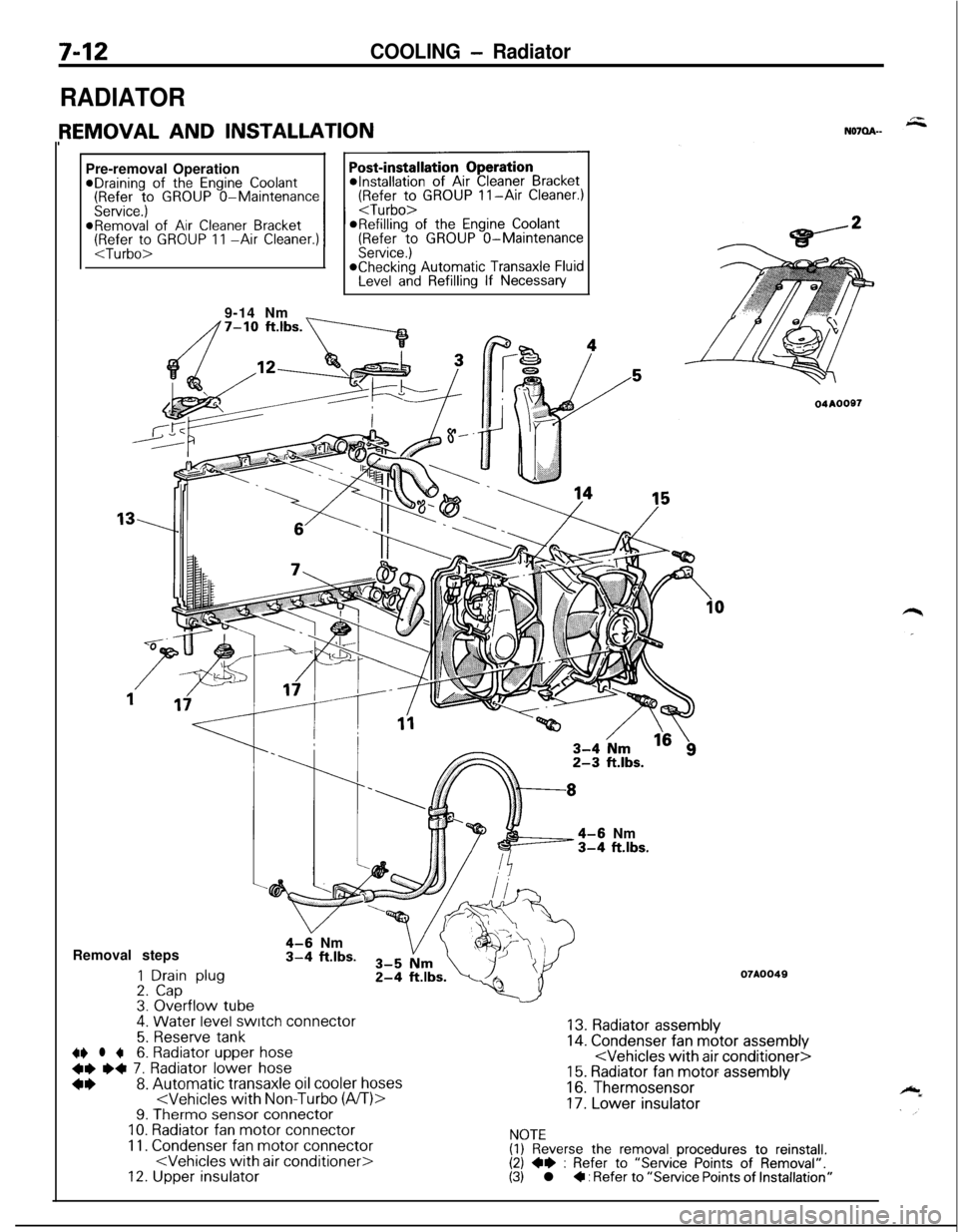
4-6 Nm3-4 ft.lbs.Removal steps
1 Drain plug2. Cap3. Overflow tube.
4-9 Nm3-4 ft.lbs.
4. Water level switch connector
5. Reserve tank~~ l +6. Radiator upper hose
+e e+ 7. Radiator lower hose
*I)8. Automatic transaxle oil cooler hoses
11. Condenser fan motor connector
04AOOS7
07A0049
13. Radiator assembly14. Condenser fan motor assembly
16. Thermosensor
17. Lower insulator
NOTE(1) Reverse the removal procedures to reinstall.(2) +e : Refer to “Service Points of Removal”.(3) l + : Refer to “Service Points of Installation”
Page 308 of 1216
9-24ENGINE - Service Adjustment Procedures
ENGINE 4.8L Engine>
SERVICE ADJUSTMENT PROCEDURES -
CHECKING COMPRESSION PRESSURENOSFFAI
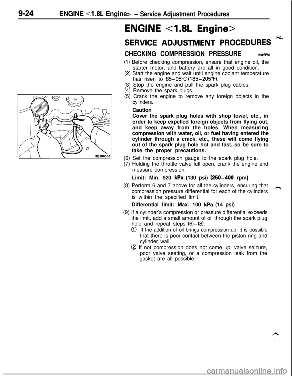
(1) Before checking compression, ensure that engine oil, the
starter motor, and battery are all in good condition.
(2) Start the engine and wait until engine coolant temperature
has risen to
85-95°C (185-205°F).
(3) Stop the engine and pull the spark plug cables.
(4) Remove the spark plugs.
(5) Crank the engine to remove any foreign objects in the
cylinders.Caution
Cover the spark plug holes with shop towel, etc., in
order to keep expelled foreign objects from flying out,
and keep away from the holes. When measuring
compression with water, oil, or fuel having entered the
cylinder through a crack, etc., these will come flying
out of the spark plug hole hot and fast, so be sure to
take the proper precautions.
(6) Set the compression gauge to the spark plug hole.
(7) Holding the throttle valve full open, crank the engine and
measure compression.
Limit: Min. 920
kPa (130 psi) [250-400 rpm]
(8) Perform 6 and 7 above for all the cylinders, ensuring that
compression pressure differential for each of the cylinders
/Iis within the specified limit.
__Differential limit: Max. 100
kPa (14 psi)
(9) If a cylinder’s compression or pressure differential exceeds
the limit, add a small amount of oil through the spark plug
hole and repeat steps (6)-(8).
0If the addition of oil brings compression up, it is possiblethat there is poor contact between the piston ring and
cylinder wall.
@ If not compression does not come up, valve seizure,
poor valve seating, or a compression leak from the
gasket are all possible.
/y
-
Page 352 of 1216
9-68ENGINE <1.8L Engine> - Piston and Connecting Rod
r-Size and maker marks
No. 1Barrel
faced
1
1 Size and maker marks
L
INo.2
ti2zza
Tapered
Barrelfaced
1 EN064
-1 No. 1 rina aarGap of
upper8. INSTALLATION OF
NO.2 PISTON RING/7. NO. 1
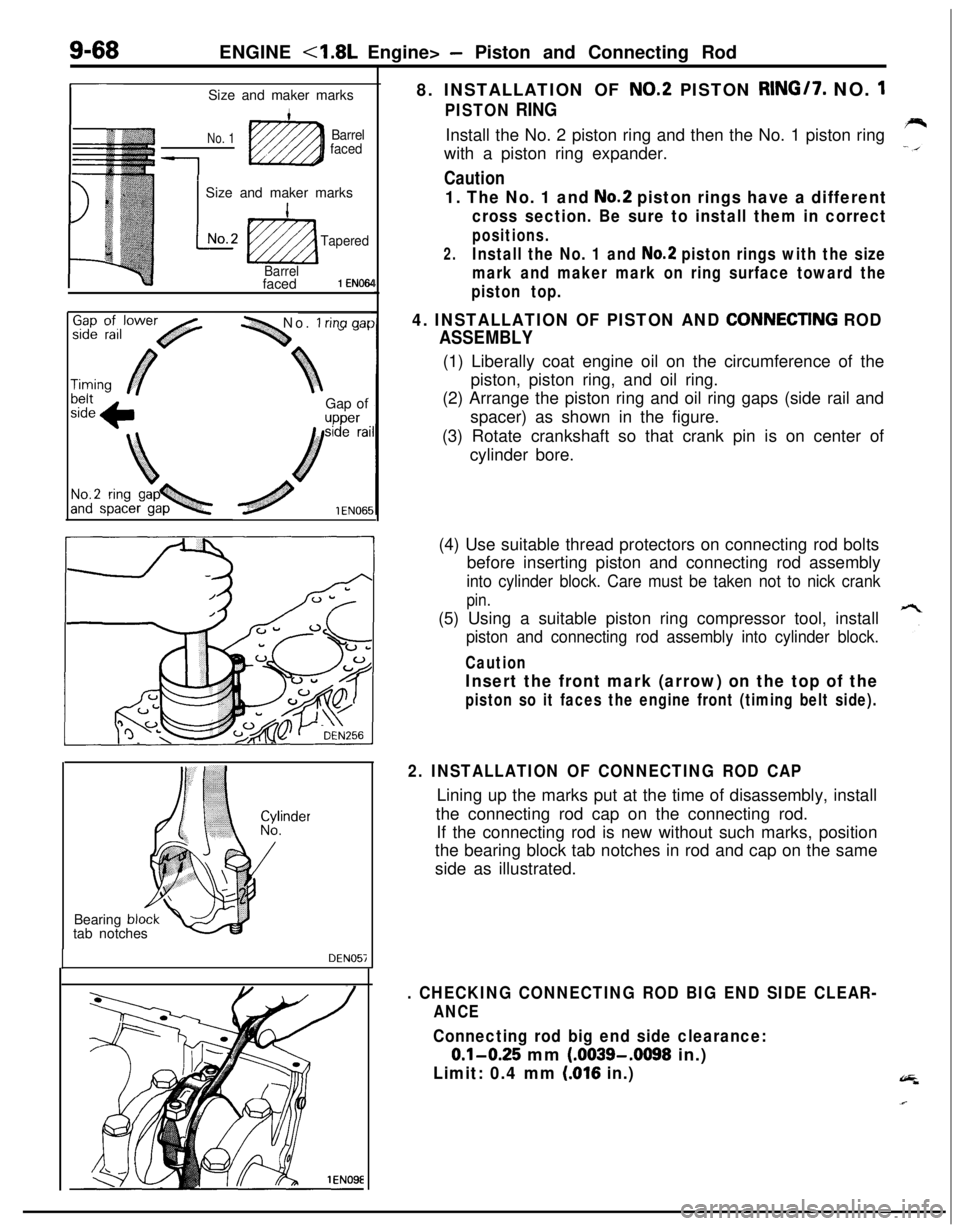
PISTON RINGInstall the No. 2 piston ring and then the No. 1 piston ring
with a piston ring expander.
Caution
1. The No. 1 and No.2 piston rings have a different
cross section. Be sure to install them in correct
positions.
2.Install the No. 1 and No.2 piston rings with the size
mark and maker mark on ring surface toward the
piston top.
4. INSTALLATION OF PISTON AND CONNECTlNG ROD
ASSEMBLY(1) Liberally coat engine oil on the circumference of the
piston, piston ring, and oil ring.
(2) Arrange the piston ring and oil ring gaps (side rail and
spacer) as shown in the figure.
(3) Rotate crankshaft so that crank pin is on center of
cylinder bore.
Bearing
bltab notches
DEN057(4) Use suitable thread protectors on connecting rod bolts
before inserting piston and connecting rod assembly
into cylinder block. Care must be taken not to nick crank
pin.(5) Using a suitable piston ring compressor tool, install
piston and connecting rod assembly into cylinder block.
Caution
Insert the front mark (arrow) on the top of the
piston so it faces the engine front (timing belt side).
2. INSTALLATION OF CONNECTING ROD CAPLining up the marks put at the time of disassembly, install
the connecting rod cap on the connecting rod.
If the connecting rod is new without such marks, position
the bearing block tab notches in rod and cap on the same
side as illustrated.
. CHECKING CONNECTING ROD BIG END SIDE CLEAR-
ANCE
Connecting rod big end side clearance:
0.1-0.25 mm (.0039-.0098 in.)
Limit: 0.4 mm (016 in.)
Page 355 of 1216
ENGINE - Crankshaft, Flwvheel and Drive Plate9-71
3EN30’lrrow mark toward
cap No,
I
RING GEAR (Engine with a manual transaxle)Check the ring gear for worn, damaged or broken teeth.
Replace the ring gear if teeth are faulty, and also check the
starter motor pinion.
Ring Gear Replacement Procedure(1) Strike outer circumference of ring gear at several points.
Caution
The ring gear cannot be removed if it is heated.(2) Install the ring gear on flywheel after heating the ring gear
to
260-280°C (500-536°F) for shrink fit.
FLYWHEEL (Engine with a manual transaxle)
(1) Visually check the clutch disc friction surface of flywheel forridge wear, streaks and seizure. Replace as necessary.
(2) If the flywheel
runout exceeds the limit, replace it.
Limit: 0.13 mm (0051 in.)
DRIVE PLATE (Engine with an automatic transaxle)Replace if deformed, damaged or cracked.
SERVICE POINTS OF REASSEMBLY
NOSUDAA
15. INSTALLATION OF UPPER BEARINGWhen reusing the main bearings, install them in their
original positions by referring to location marking made at
the time of removal.
Be sure that oil holes in bearings align with those in cylinder
block.
13. INSTALLATION OF LOWER BEARINGMake sure that a bearing without oil groove is used as
lower bearing.
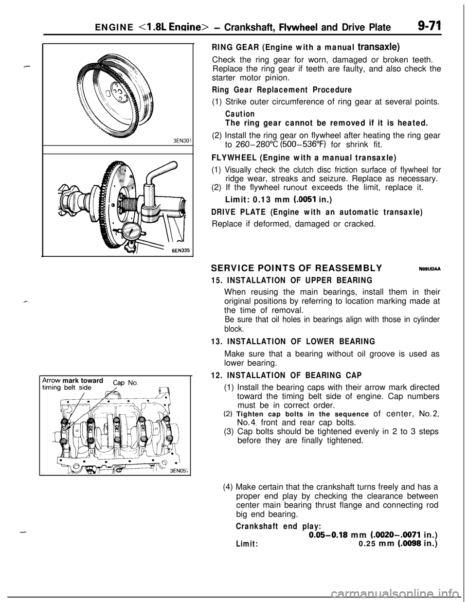
12. INSTALLATION OF BEARING CAP(1) Install the bearing caps with their arrow mark directed
toward the timing belt side of engine. Cap numbers
must be in correct order.(2) Tighten cap bolts in the sequence of center,
No.2,
No.4. front and rear cap bolts.
(3) Cap bolts should be tightened evenly in 2 to 3 steps
before they are finally tightened.
(4) Make certain that the crankshaft turns freely and has a
proper end play by checking the clearance between
center main bearing thrust flange and connecting rod
big end bearing.
Crankshaft end play:
0.05-0.18 mm (.0020-.0071 in.)
Limit:0.25 mm (.0098 in.)
Page 358 of 1216
9-74ENGINE <2.0L DOHC Engine>- Service Adjustment Procedures
ENGINE <2.0L DOHC Engine>
SERVICE ADJUSTMENT PROCEDURES pi
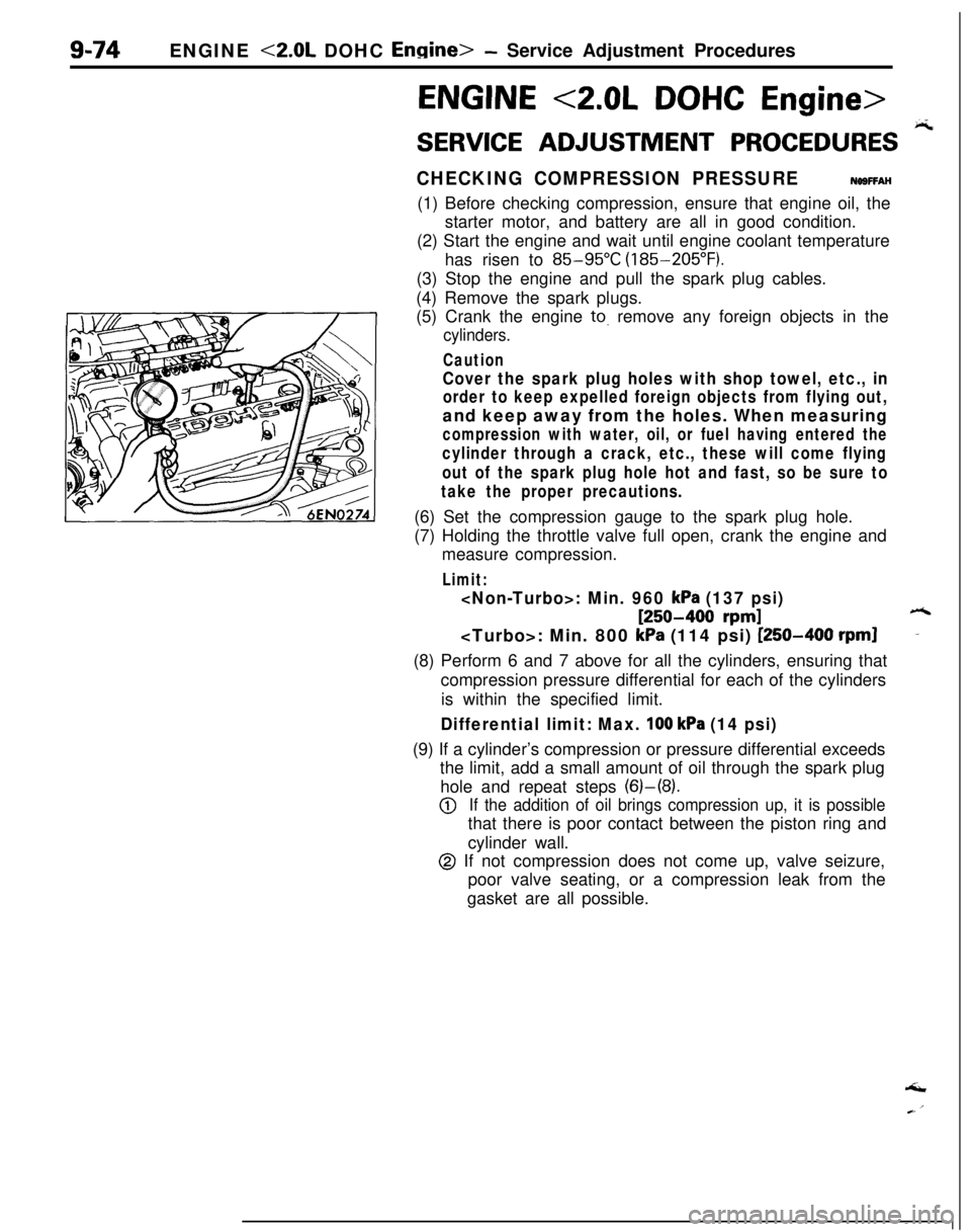
CHECKING COMPRESSION PRESSURENOSFFAH(1) Before checking compression, ensure that engine oil, the
starter motor, and battery are all in good condition.
(2) Start the engine and wait until engine coolant temperature
has risen to
85-95°C (185-205°F).
(3) Stop the engine and pull the spark plug cables.
(4) Remove the spark plugs.
(5) Crank the engine
to. remove any foreign objects in the
cylinders.
Caution
Cover the spark plug holes with shop towel, etc., in
order to keep expelled foreign objects from flying out,and keep away from the holes. When measuring
compression with water, oil, or fuel having entered the
cylinder through a crack, etc., these will come flying
out of the spark plug hole hot and fast, so be sure to
take the proper precautions.(6) Set the compression gauge to the spark plug hole.
(7) Holding the throttle valve full open, crank the engine and
measure compression.
Limit:
[250-400 rpm]6
kPa (114 psi) [250-400 rpml-(8) Perform 6 and 7 above for all the cylinders, ensuring that
compression pressure differential for each of the cylinders
is within the specified limit.
Differential limit: Max. 100 kPa (14 psi)(9) If a cylinder’s compression or pressure differential exceeds
the limit, add a small amount of oil through the spark plug
hole and repeat steps (6)-(8).
@If the addition of oil brings compression up, it is possiblethat there is poor contact between the piston ring and
cylinder wall.
@ If not compression does not come up, valve seizure,
poor valve seating, or a compression leak from the
gasket are all possible.‘I
Page 367 of 1216
r-.ENGINE <2.0L DOHC Engine>
- Engine AssemblyS-83
OlA0177
-mpp.-/- --OlA0553
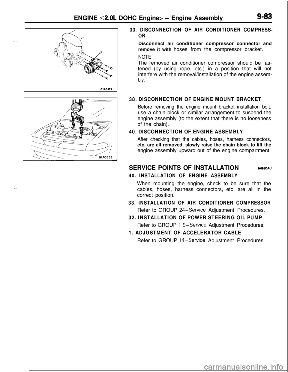
33. DISCONNECTION OF AIR CONDITIONER COMPRESS-
ORDisconnect air conditioner compressor connector and
remove it with hoses from the compressor bracket.
NOTEThe removed air conditioner compressor should be fas-
tened (by using rope, etc.) in a position that will not
interfere with the removal/installation of the engine assem-
bly.
38. DISCONNECTION OF ENGINE MOUNT BRACKET
Before removing the engine mount bracket installation bolt,use a chain block or similar arrangement to suspend the
engine assembly (to the extent that there is no looseness
of the chain).
40. DISCONNECTION OF ENGINE ASSEMBLY
After checking that the cables, hoses, harness connectors,etc. are all removed, slowly raise the chain block to lift the
engine assembly upward out of the engine compartment.
SERVICE POINTS OF INSTALLATION
NOSSDAU
40. INSTALLATION OF ENGINE ASSEMBLYWhen mounting the engine, check to be sure that the
cables, hoses, harness connectors, etc. are all in the
correct position.
33. INSTALLATION OF AIR CONDITIONER COMPRESSORRefer to GROUP
24-Service Adjustment Procedures.
32. INSTALLATION OF POWER STEERING OIL PUMPRefer to GROUP 1
g-service Adjustment Procedures.
1. ADJUSTMENT OF ACCELERATOR CABLERefer to GROUP 14-Service Adjustment Procedures.
Page 369 of 1216
ENGINE <2.0L DOHC Engine> -Camshafts and Camshaft Oil Seals9-85Plastic hammer
Intake side
Exhaust side
Jzzl
(22
Slits
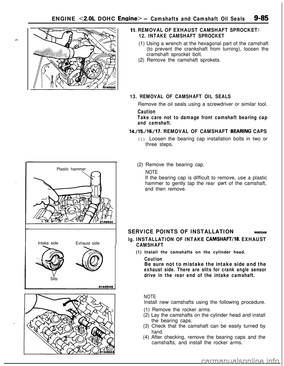
11. REMOVAL OF EXHAUST CAMSHAFT SPROCKET/
12. INTAKE CAMSHAFT SPROCKET(1) Using a wrench at the hexagonal part of the camshaft
(to prevent the crankshaft from turning), loosen the
cramshaft sprocket bolt.
(2) Remove the camshaft sprokets.
13. REMOVAL OF CAMSHAFT OIL SEALSRemove the oil seals using a screwdriver or similar tool.
Caution
Take care not to damage front camshaft bearing cap
and camshaft.
14./15./16./17. REMOVAL OF CAMSHAFT BEARfNG CAPS(1) Loosen the bearing cap installation bolts in two or
three steps.
(2) Remove the bearing cap.
NOTEIf the bearing cap is difficult to remove, use a plastic
hammer to gently tap the rear
.part of the camshaft,
and then remove.
SERVICE POINTS OF INSTALLATIONNO92DAB
lg. INSTALLATION OF INTAKE CAMSHAFT/18. EXHAUST
CAMSHAFT(1) Install the camshafts on the cylinder head.
Caution
Be sure not to mistake the intake side and the
exhaust side. There are slits for crank angle sensor
drive in the rear end of the intake camshaft.
NOTEInstall new camshafts using the following procedure.
(1) Remove the rocker arms.
(2) Lay the camshafts on the cylinder head and install
the bearing caps.
(3) Check that the camshaft can be easily turned by
hand.(4) After checking, remove the bearing caps and the
camshafts, and install the rocker arms.