alarm MITSUBISHI ECLIPSE 1991 Service Manual
[x] Cancel search | Manufacturer: MITSUBISHI, Model Year: 1991, Model line: ECLIPSE, Model: MITSUBISHI ECLIPSE 1991Pages: 1216, PDF Size: 67.42 MB
Page 571 of 1216
i-._AUTO-CRUISE CONTROL SYSTEM
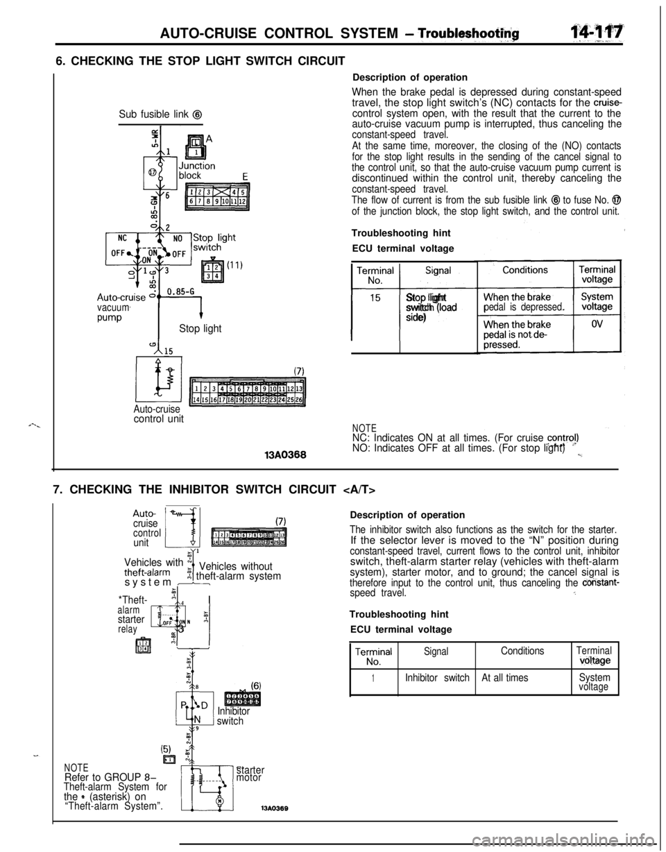
- Troubltyshootf$6. CHECKING THE STOP LIGHT SWITCH CIRCUIT
Sub fusible link @
vacuum
w-vStop light
Auto-cruisecontrol unit13A0366Description of operation
When the brake pedal is depressed during constant-speedtravel, the stop light switch’s (NC) contacts for the cruise-control system open, with the result that the current to the
auto-cruise vacuum pump is interrupted, thus canceling the
constant-speed travel.
At the same time, moreover, the closing of the (NO) contacts
for the stop light results in the sending of the cancel signal to
the control unit, so that the auto-cruise vacuum pump current is
discontinued within the control unit, thereby canceling the
constant-speed travel.
The flow of current is from the sub fusible link
@I to fuse No. @
of the junction block, the stop light switch, and the control unit.Troubleshooting hint
ECU terminal voltage
TerminalSignal
No.
15
t-i-
Stop light
switch (load
side)pedal is depressed.
NOTENC: Indicates ON at all times. (For cruise contra!)NO: Indicates OFF at all times. (For stop light)l,_7. CHECKING THE INHIBITOR SWITCH CIRCUIT
Auto-
cruise
controlunit
Vehicles with x
theft-alarmIVehicles without5 theft-alarm systemsystem br
*Theft-’ nI Ialarm, ._I
starterz
relayQlOF: N A_ 3
Inhibitor
switchDescription of operation
The inhibitor switch also functions as the switch for the starter.If the selector lever is moved to the “N” position during
constant-speed travel, current flows to the control unit, inhibitorswitch, theft-alarm starter relay (vehicles with theft-alarm
system), starter motor, and to ground; the cancel signal istherefore input to the control unit, thus canceling the constant-speed travel.5Troubleshooting hint
ECU terminal voltage
TeE!alSignalConditionsTerminalvoltage
1Inhibitor switchAt all timesSystemvoltage
C.starter
motor13A036BNOTERefer to GROUP 8-Theft-alarm System forthe + (asterisk) on“Theft-alarm System”.
Page 585 of 1216
AUTO-CRUISE CONTROL SYSTEM - Troubleshooting14L’1.31”
-=cA/T>
SUB
LIN
!z
A
c
0
10A
c3
c3
h'HEN{EY IS?EMOVED
c
2Iu-zn
r
:ONI(IG1) ,INIGNITIONST)SWITCH(IG2)
-1
SIBLE
4
raII31
c-47
1
J/B
C-52
(liIals14r51sl]
IGNITISWITCI
1 J/B10A
3 c-50
7Flimsq’
z
6 c-45
14
LW$NATION
9
I, ,D-05
‘71(2~3~41516~715“‘I0 1lo~llll~l3ll4pm7
WITH
iEK;Si-
#gpT
ALARMSYSTEM I SYSTEMI,
AUTO-CRUI6E,23 CONTROL UNIT
73
i
GND
14
m10
C-67
m
0
KX35-AC-Ul516-NCn
SELF-DIAGNOSISCOt$NECTOR
c-30 :
FRONT 'SIDE
piELRq
REVERSE ,-SIDE
Page 897 of 1216
AUTOMATIC TRANSAXLE - Troubleshooting21-203
CIRCUIT DIAGRAM
J/B
63IOA
0
'13l-----AWD1
cL
13 C-67
1
'OU'EiRaPPLl
--b
7
1'
I
I
3
xl:- 71
03
4
I
L--
-----------------16 C-502zs
4
C-58
El
THEFT-ALARM
CONTROL UNIT
INHIBITORSWITCH
B-25
r
STARTER MOTOR
X35-AC-U0705-NC
Page 1055 of 1216

BODY - Troubleshooting234'1
CENTRAL DOOR LOCKING SYSTEM
CIRCUIT DIAGRAM..-
,-.
SUB FU0IBLELINK 8
g
J/Bk 1 c-47 'B
@
L
10A
L
is411
J/B
L
4c
c-51
c-49
12
al34
3 E-64
DOOR LOCKE-49DOOR LOCKE-09
KX3b-AC-WIOB-Xi:
Page 1056 of 1216
2342BODY - Troubleshooting
CENTRAL DOOR LOCKING SYSTEM
CIRCUIT DIAGRAM
IGNITISW1 TCH
c
c-54 c
ONIGI(ACC) SW-
r'334
9P------.IX
0
10A
\/------.1
43bC-52-:
THEFT-ALARMg$;ROL $jr------51z------.
I
CH(IG1)
7
431OA
1
fl
fiie;yLOCK
c-34x
f!iiGqII
?
$4m5--- -----1!2---w---w---: (II
IL-++;I
II
j2s9
L--------------- _
C-20 5~7f.f5,8m~ii-~,i;----'
I1
3 E-50
3 E-64
1
1
X95-AC-Ull00-NC
DOOR LOCKE-09%%8°iIDE,
m
DOOR LOCKE-49
ACTUATOR
Page 1057 of 1216
BODY - Troubleshooting23-13
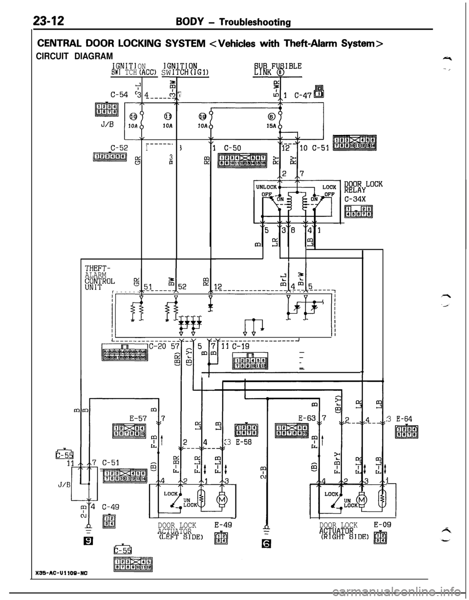
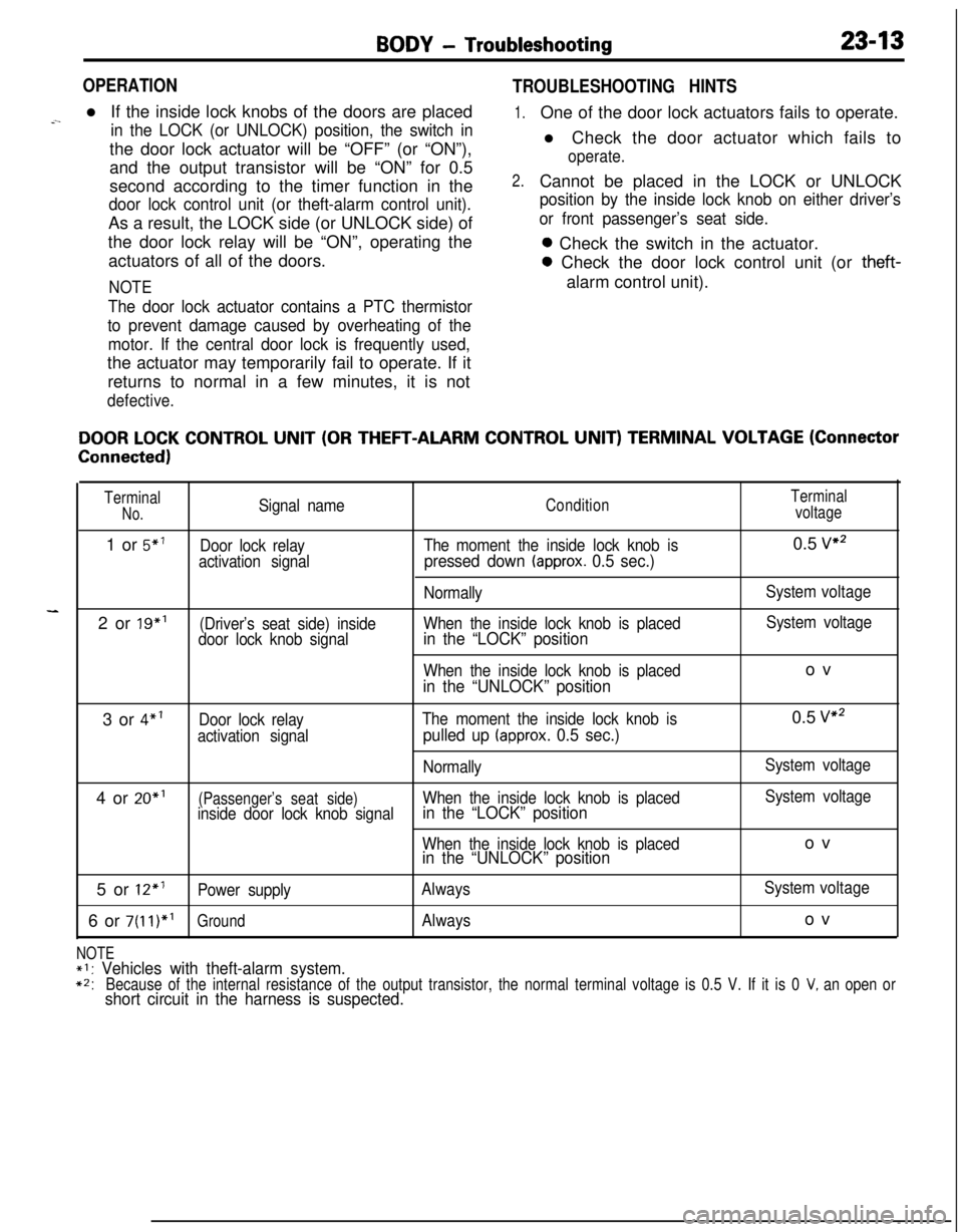
OPERATION
TROUBLESHOOTING HINTS
-.l If the inside lock knobs of the doors are placedin the LOCK (or UNLOCK) position, the switch inthe door lock actuator will be “OFF” (or “ON”),
and the output transistor will be “ON” for 0.5
second according to the timer function in the
door lock control unit (or theft-alarm control unit).As a result, the LOCK side (or UNLOCK side) of
the door lock relay will be “ON”, operating the
actuators of all of the doors.
NOTE
The door lock actuator contains a PTC thermistor
to prevent damage caused by overheating of the
motor. If the central door lock is frequently used,the actuator may temporarily fail to operate. If it
returns to normal in a few minutes, it is not
defective.
1.
2.One of the door lock actuators fails to operate.
l Check the door actuator which fails to
operate.Cannot be placed in the LOCK or UNLOCK
position by the inside lock knob on either driver’s
or front passenger’s seat side.0 Check the switch in the actuator.0 Check the door lock control unit (or
theft-alarm control unit).
DOOR LOCK CONTROL UNIT (OR THEFT-ALARM CONTROL UNIT) TERMINAL VOLTAGE (Connector
Connected)
TerminalSignal nameConditionTerminalNo.voltage1 or
5”’Door lock relayThe moment the inside lock knob is0.5 vs2
activation signal
pressed down (approx. 0.5 sec.)
NormallySystem voltage2 or 19”’
(Driver’s seat side) insideWhen the inside lock knob is placedSystem voltage
door lock knob signalin the “LOCK” position
When the inside lock knob is placedov
in the “UNLOCK” position3 or
4”’Door lock relayThe moment the inside lock knob is0.5 v2
activation signalpulled up (approx. 0.5 sec.)
NormallySystem voltage4 or 20”’
(Passenger’s seat side)When the inside lock knob is placedSystem voltage
inside door lock knob signalin the “LOCK” position
When the inside lock knob is placedovin the “UNLOCK” position5 or
12*’Power supplyAlwaysSystem voltage6 or
7(11)*’GroundAlwaysov
NOTE*I: Vehicles with theft-alarm system.
*2:Because of the internal resistance of the output transistor, the normal terminal voltage is 0.5 V. If it is 0 V, an open orshort circuit in the harness is suspected.
Page 1078 of 1216
23-34BODY - Hood
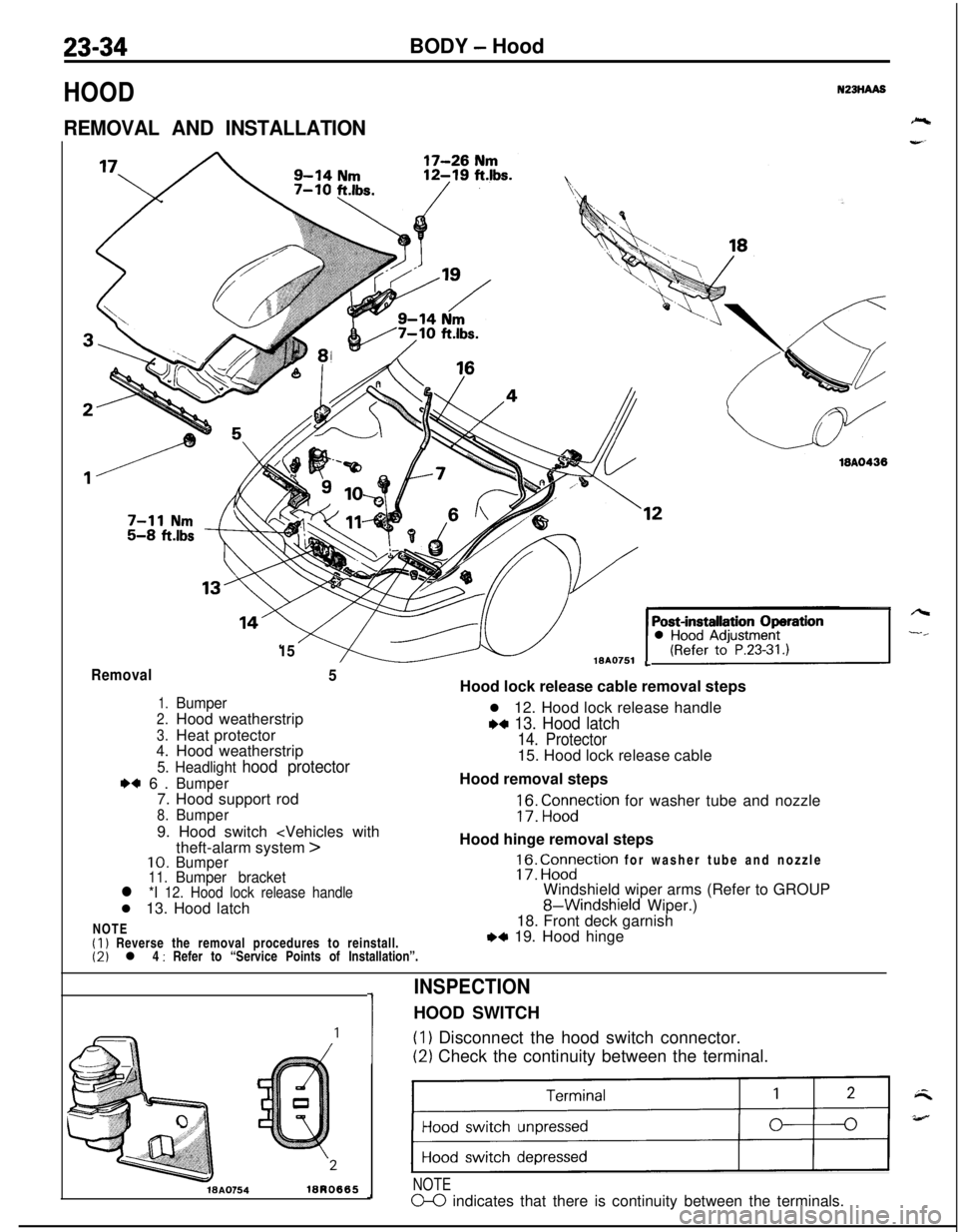
HOOD
REMOVAL AND INSTALLATION
N23HAA8
1518AO751
18A0438
LRemoval5
1.Bumper
2.Hood weatherstrip
3.Heat protector4.Hood weatherstrip
5. Headlight hood protector
I)+ 6.Bumper7. Hood support rod
8.Bumper9. Hood switch
>10.Bumper11.Bumper bracketl *I 12. Hood lock release handlel 13. Hood latch
NOTE
(1) Reverse the removal procedures to reinstall.(2) l 4 : Refer to “Service Points of Installation”.Hood lock release cable removal steps
l 12. Hood lock release handle
w 13. Hood latch
14. Protector15. Hood lock release cable
Hood removal steps
;f3: “,;n,yction for washer tube and nozzle
Hood hinge removal steps
17: ig?ction for washer tube and nozzle
Windshield wiper arms (Refer to GROUP
8-Windshield Wiper.)
18. Front deck garnish
,*I 19. Hood hinge
1
INSPECTIONHOOD SWITCH(I
1 Disconnect the hood switch connector.
(2) Check the continuity between the terminal.
WA0754lBRO665
)
NOTE
m indicates that there is continuity between the terminals.
Page 1080 of 1216
23-36BODY - Liftgate
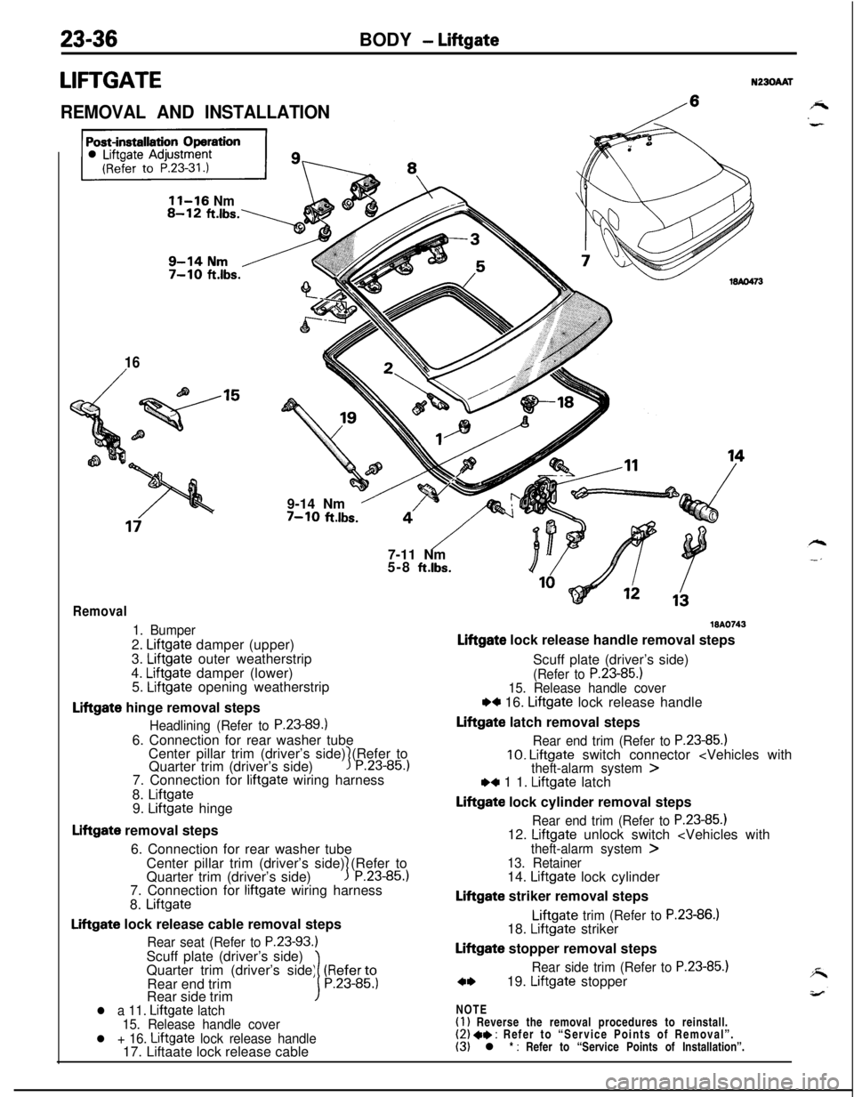
LIFTGATEN230AAT
REMOVAL AND INSTALLATION/
11-16 Nm
16
/9-14 Nm
’7-10 ft.lbs.
“‘/- -$j7-11 Nm
5-8
ft.lbs.
Removal
1. Bumper2.
Liftgate damper (upper)
3.
Liftgate outer weatherstrip
4.
Liftgate damper (lower)
5. Liftgate opening weatherstrip
Liftgate hinge removal steps
Headlining (Refer to P.23-89.16. Connection for rear washer tube
Center pillar trim (driver’s side) (Refer to
Quarter trim (driver’s side)
3P.23-85.)7. Connection for
liftgate wiring harness
8.
Liftgate9. Liftgate hinge
Liftgate removal steps
6. Connection for rear washer tube
Center pillar trim (driver’s side) (Refer to
Quarter trim (driver’s side)
1P.23-85.)7. Connection for
liftgate wiring harness
8.
Liftgate
Liftgate lock release cable removal steps
Rear seat (Refer to P.23-93.)Scuff plate (driver’s side)
Quarter trim (driver’s side) (Referto
Rear end trim
1P.23-85.)Rear side trim
l a 11. Liftgate latch
15. Release handle cover
l + 16. Liftgate lock release handle17. Liftaate lock release cable
WA0743
Liftgate lock release handle removal steps
Scuff plate (driver’s side)
(Refer to P.23-85.)15. Release handle cover
w 16. Liftgate lock release handle
Liftgate latch removal steps
Rear end trim (Refer to P.23-85.)10. Liftgate switch connector
Liftgate lock cylinder removal steps
Rear end trim (Refer to P.23-85.112. Liftgate unlock switch
13. Retainer14. Liftgate lock cylinder
Liftgate striker removal stepsLiftgate
trim (Refer to P.23-86.)18. Liftgate striker
Liftgate stopper removal steps
Rear side trim (Refer to P.23-85.)
c*19. Liftgate stopper
NOTE
(1) Reverse the removal procedures to reinstall.(2) 4* : Refer to “Service Points of Removal”.(3) l * : Refer to “Service Points of Installation”.
Page 1113 of 1216
BODY - Power Window/Door Handle and Latch23-69
I-
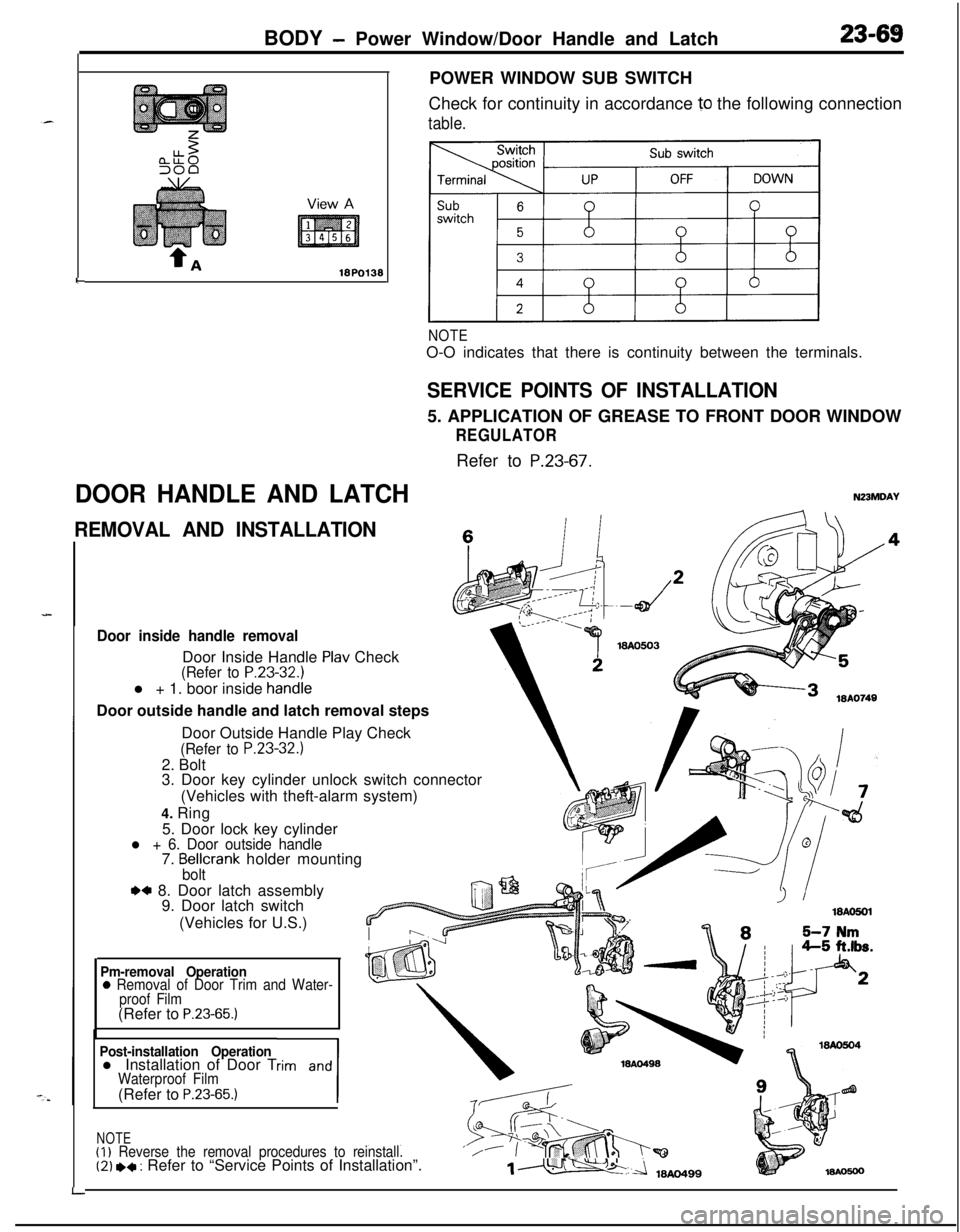
DOOR HANDLE AND LATCHPOWER WINDOW SUB SWITCH
Check for continuity in accordance
10 the following connection
table.
NOTEO-O indicates that there is continuity between the terminals.
SERVICE POINTS OF INSTALLATION5. APPLICATION OF GREASE TO FRONT DOOR WINDOW
REGULATORRefer to
P.23-67.
N23MDAY
REMOVAL AND INSTALLATIONc
Door inside handle removalDoor Inside Handle
Plav Check(Refer to P.23-32.1l + 1. boor inside
handieDoor outside handle and latch removal steps
LDoor Outside Handle Play Check
(Refer to P.23-32.)2. Bolt
3. Door key cylinder unlock switch connector
(Vehicles with theft-alarm system)
4. Ring
5. Door lock key cylinder
l + 6. Door outside handle7. Bellcrank holder mountingbolt
.a 8. Door latch assembly
9. Door latch switch
(Vehicles for U.S.)
Pm-removal Operation0 Removal of Door Trim and Water-
proof Film(Refer to
P.23-65.)
Post-installation Operationl Installation of Door Trim and
1
Waterproof Film(Refer to P.23-65.)
NOTE(I)
Reverse the removal procedures to reinstall.‘/(2) *+ : Refer to “Service Points of Installation”.1m
Page 1114 of 1216
23-70BODY- Door Handle and Latch/Central Door Lockina Svstem
I18AO750 1lBY3611 I.- .--,
!-
II
T!3123
18PO39i
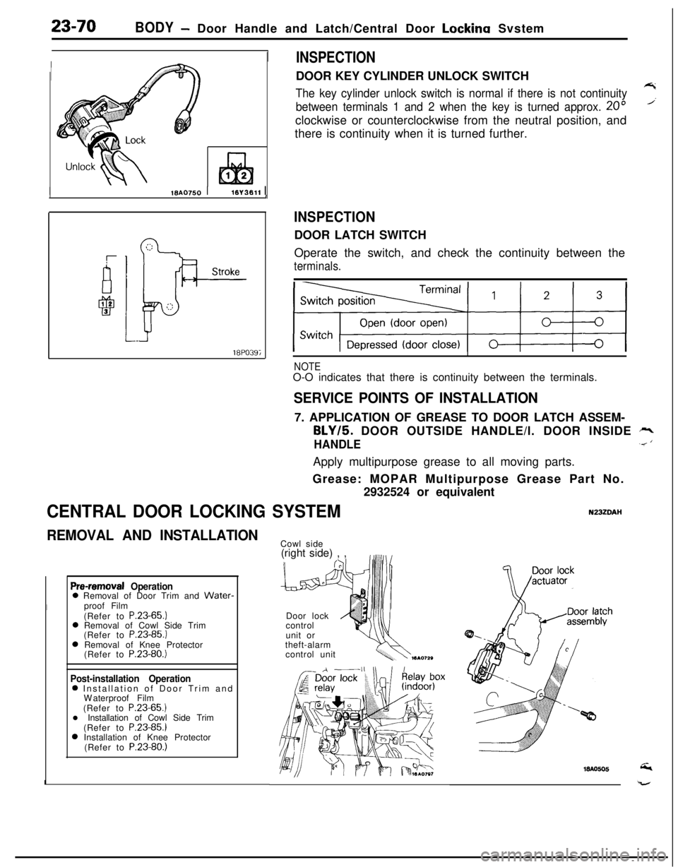
INSPECTIONDOOR KEY CYLINDER UNLOCK SWITCH
The key cylinder unlock switch is normal if there is not continuity7
between terminals 1 and 2 when the key is turned approx. 20”’clockwise or counterclockwise from the neutral position, and
there is continuity when it is turned further.
INSPECTIONDOOR LATCH SWITCH
Operate the switch, and check the continuity between the
terminals.
NOTEO-O indicates that there is continuity between the terminals.
SERVICE POINTS OF INSTALLATION7. APPLICATION OF GREASE TO DOOR LATCH ASSEM-
BLY/5. DOOR OUTSIDE HANDLE/l. DOOR INSIDE rr,
HANDLE.< ‘Apply multipurpose grease to all moving parts.
Grease: MOPAR Multipurpose Grease Part No.
2932524 or equivalent
CENTRAL DOOR LOCKING SYSTEMN23ZDAI-I
REMOVAL AND INSTALLATION
Pre-removal Operation0 Removal of Door Trim and Water-
Iproof Film
(Refer to P.23-65.)
0 Removal of Cowl Side Trim
(Refer to P.23-85.)
0 Removal of Knee Protector
(Refer to P.23-80.)
Post-installation Operation0 Installation of Door Trim and
Waterproof Film
(Refer to P.23-65.)
l Installation of Cowl Side Trim
(Refer to P.23-85.)
0 Installation of Knee Protector
(Refer to P.23-80.)
ICowl side
(right side) , ,
Door lock
control
unit or
theft-alarm
control unit