fuel filter MITSUBISHI ECLIPSE 1991 Service Manual
[x] Cancel search | Manufacturer: MITSUBISHI, Model Year: 1991, Model line: ECLIPSE, Model: MITSUBISHI ECLIPSE 1991Pages: 1216, PDF Size: 67.42 MB
Page 35 of 1216
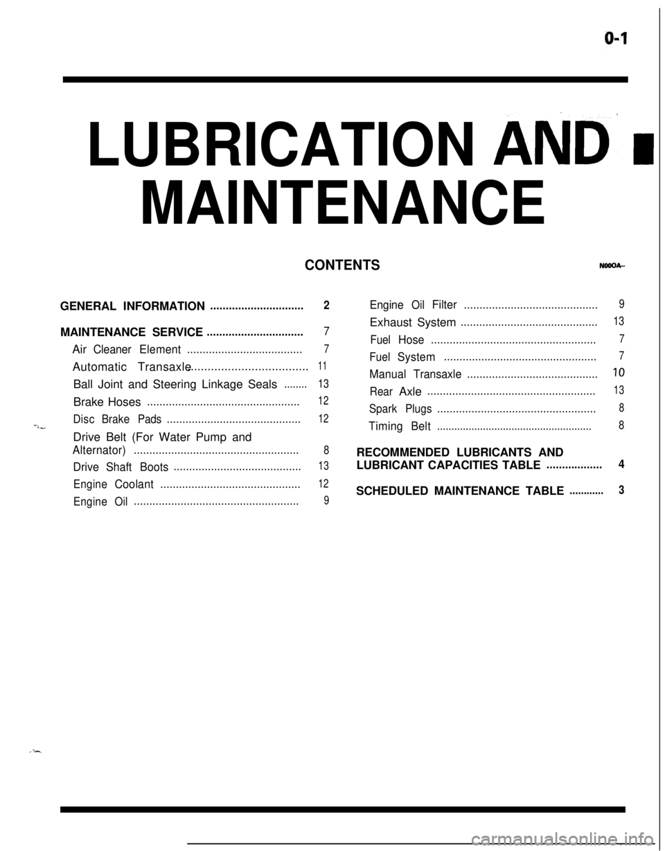
LUBRICATION AND’ I
MAINTENANCE
CONTENTSGENERAL INFORMATION
..............................2MAINTENANCE SERVICE
...............................7Air
CleanerElement.....................................7Automatic Transaxle....................................
11Ball Joint and Steering Linkage Seals
........13Brake Hoses
.................................................12
DiscBrakePads...........................................12-lbDrive Belt (For Water Pump and
Alternator).....................................................8
DriveShaftBoots.........................................13
EngineCoolant.............................................12
EngineOil.....................................................9
EngineOilFilter...........................................9Exhaust System
............................................13
FuelHose.....................................................7
FuelSystem.................................................7
ManualTransaxle..........................................10
RearAxle......................................................13
SparkPlugs...................................................8
TimingBelt......................................................8RECOMMENDED LUBRICANTS AND
LUBRICANT CAPACITIES TABLE
..................4SCHEDULED MAINTENANCE TABLE
............3
Page 37 of 1216
LUBRICATION AND MAINTENANCE - Scheduled MaintenanCe Table. &3
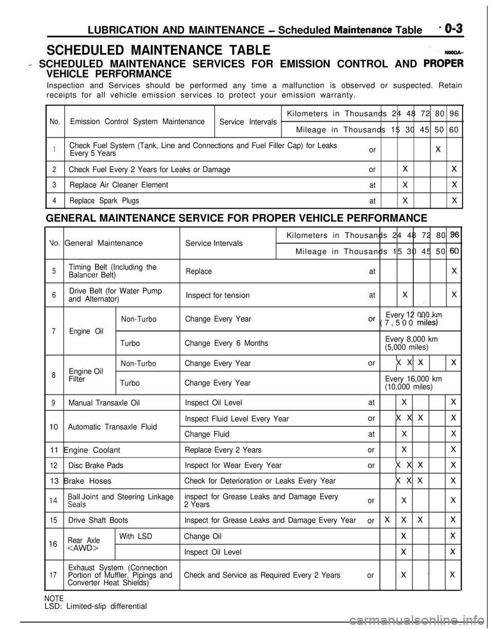
SCHEDULED MAINTENANCE TABLE1
- SCHEDULED MAINTENANCE SERVICES FOR EMISSION CONTROL AND PRO;;
VEHICLE PERFORMANCEInspection and Services should be performed any time a malfunction is observed or suspected. Retain
receipts for all vehicle emission services to protect your emission warranty.
Kilometers in Thousands 24 48 72 80 96
No.Emission Control System Maintenance
Service IntervalsMileage in Thousands 15 30 45 50 60
1Check Fuel System (Tank, Line and Connections and Fuel Filler Cap) for Leaks
Every 5 YearsorX
2Check Fuel Every 2 Years for Leaks or DamageorXX
3Replace Air Cleaner Element
atXX
4Replace Spark Plugs
atXXGENERAL MAINTENANCE SERVICE FOR PROPER VEHICLE PERFORMANCE
Yo. General Maintenance
Service IntervalsKilometers in Thousands 24 48 72 80 9cMileage in Thousands 15 30 45 50
6C
5Timing Belt (Including theBalancer Belt)ReplaceatX
6Drive Belt (for Water Pump
and Alternator)Inspect for tensionatXX.’
Non-TurboChange Every YearEvery 12 000 kmOr (7,500 miles).
7Engine Oil
TurboChange Every 6 MonthsEvery 8,000 km
(5,000 miles)
Non-TurboChange Every Yearor X X XX
8Engine Oil
Filter
TurboChange Every YearEvery 16,000 km
(10,000 miles)
9Manual Transaxle OilInspect Oil LevelatX.X
Inspect Fluid Level Every Yearor X X XX
10Automatic Transaxle Fluid
Change FluidatXX11 Engine Coolant
Replace Every 2 YearsorXX
12Disc Brake PadsInspect for Wear Every Yearor X X XX13 Brake Hoses
Check for Deterioration or Leaks Every YearX X XX
l 4Beiloint and Steering Linkageinspect for Grease Leaks and Damage Every
2 YearsorXX
15Drive Shaft BootsInspect for Grease Leaks and Damage Every Yearor XXXX
Rear Axle
With LSDChange OilXX1 6
Exhaust System (Connection17Portion of Muffler, Pipings andCheck and Service as Required Every 2 Yearsorx -xConverter Heat Shields)
NOTELSD: Limited-slip differential
Page 39 of 1216
LUBRICATION AND MAINTENANCE - Recommended Lubrie’ntsand Lubrtcant Capacttles Table
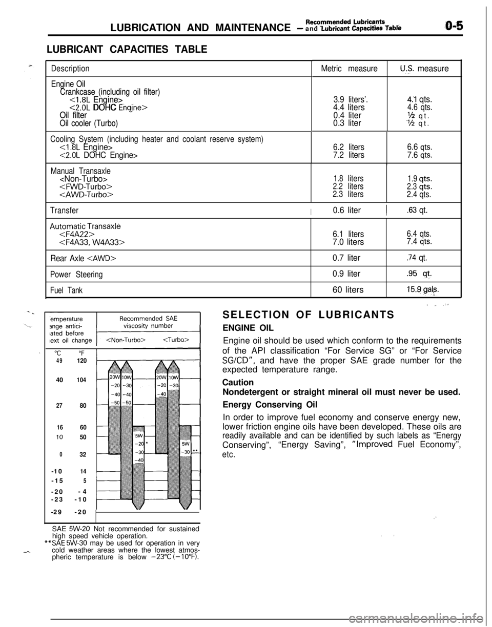
LUBRICANT CAPACITIES TABLE
Description
Engine Oil Engine Oil
Crankcase (including oil filter) Crankcase (including oil filter)
<1.8L Engine><1.8L Engine><2.0L DOHC Engine><2.0L DOHC Enaine>Oil filter Oil filter
Oil cooler (Turbo) Oil cooler (Turbo)
Metric measureU.S. measure
3.9 liters’.4.4 liters
0.4 liter
0.3 liter
4.‘1 qts.4.6 qts.
‘h qt.Y2 qt.
Cooling System (including heater and coolant reserve system)
<2.0L DOHC Engine>6.2 liters
7.2 liters6.6
qts.
7.6 qts.
Manual Transaxle
1.8liters1.9qts.2.2liters2.3qts.
2.3liters
2.4qts.
Transfer
I0.6 literI.63 qt.
Au:oFmqaAtF2pnsaxle
Rear Axle
Power Steering
Fuel Tank
"C“F4912040
104
27
80
1660
1050
032-10
14-15
5-20-4
-23-10
-29-20
6.1 liters6.4 qts.
7.0 liters7.4 qts.
0.7 liter.74 qt.
0.9 liter.95 sf.60 liters
15.9 gal?.
’ ~ “.SELECTION OF LUBRICANTS
ENGINE OIL
Engine oil should be used which conform to the requirements
of the API classification “For Service SG” or “For Service
SGKD”, and have the proper SAE grade number for the
expected temperature range.
Caution
Nondetergent or straight mineral oil must never be used.
Energy Conserving Oil
In order to improve fuel economy and conserve energy new,
lower friction engine oils have been developed. These oils are
readily available and can be identified by such labels as “EnergyConserving”,“Energy Saving”,“Improved Fuel Economy”,
etc.
/”SAE
5W-20 Not recommended for sustained
high speed vehicle operation.**SAE
5W-30 may be used for operation in very
cold weather areas where the lowest atmos-
pheric temperature is below
-23°C (-10°F).
Page 41 of 1216
LUBRICATION AND MAINTENANCE - Maintenance Service
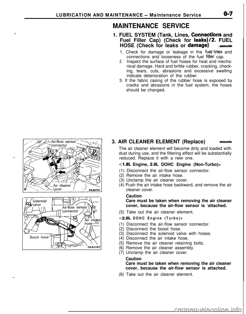
MAINTENANCE SERVICE1. FUEL SYSTEM (Tank, Lines,
Connect%ms and
Fuel Filler Cap) (Check for
leaks)/2. FUEL
HOSE (Check for leaks or
damage)1 NSOSAGtib1. Check for damage or leakage in the fuet
lines and
connections and looseness of the fuel
fi!:ler cap.
2.Inspect the surface of fuel hoses for heat and mecha-
nical damage. Hard and brittle rubber, cracking, check-
ing, tears, cuts, abrasions and excessive swelling
indicate deterioration of the rubber.
3. If the fabric casing of the rubber hose is exposed by
cracks and abrasions in the fuel system, the hoses
should be changed.
3. AIR CLEANER ELEMENT (Replace)
NOOSAKBbThe air cleaner element will become dirty and loaded with
dust during use, and the filtering effect will be substantially
reduced. Replace it with a new one.
<1.8L Engine, 2.0L DOHC Engine (Non-Turbo)>
(1) Disconnect the air-flow sensor connector.
(2) Remove the air intake hose.
(3) Unclamp the air cleaner cover.
(4) Push the air intake hose backward, and remove the air
cleaner cover.
Caution
Care must be taken when removing the air cleaner
cover, because the air-flow sensor is ‘attached.
(5) Take out the air cleaner element.
<2.0L DOHC Engine (Turbo)>
(1) Disconnect the air-flow sensor connector.
(2) Disconnect the boost hose.
(3) Disconnect the solenoid valve with hoses.
(4) Disconnect the air intake hose.
(5) Remove the air cleaner retaining bolts.
(6) Remove the air cleaner assembly.
(7) Unclamp the air cleaner cover.
Caution
Care must be taken when removing the air cleaner
cover, because the air-flow sensor is attached.
(8) Take out the air cleaner element.
Page 302 of 1216
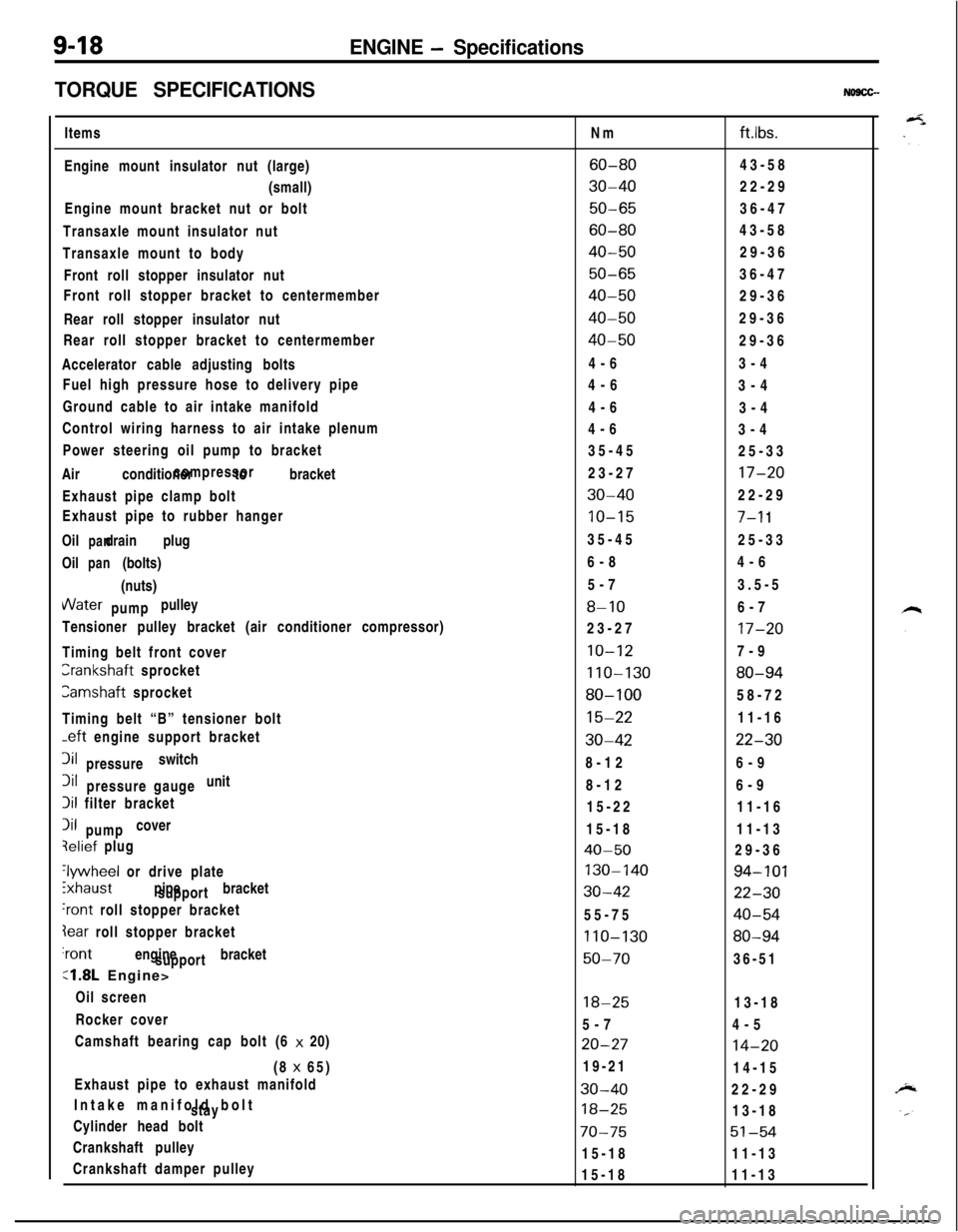
9-18ENGINE - Specifications
TORQUE SPECIFICATIONS
NO9CG-Items
Engine mount insulator nut (large)
(small)
Engine mount bracket nut or bolt
Transaxle mount insulator nut
Transaxle mount to body
Front roll stopper insulator nut
Front roll stopper bracket to centermember
Rear roll stopper insulator nut
Rear roll stopper bracket to centermember
Accelerator cable adjusting bolts
Fuel high pressure hose to delivery pipe
Ground cable to air intake manifold
Control wiring harness to air intake plenum
Power steering oil pump to bracket
Air conditioner to bracketcompressor
Exhaust pipe clamp bolt
Exhaust pipe to rubber hanger
Oil drain plug
panOil (bolts)
pan(nuts)VVater pulley
pump
Tensioner pulley bracket (air conditioner compressor)
Timing belt front coverCrankshaft sprocket
Camshaft sprocket
Timing belt “B” tensioner bolt
-eft engine support bracket3il switch
pressure3il unit
pressure gauge
Iii filter bracket
Iii cover
pumpqelief plug
‘lywheel or drive plate
ixhaust pipe bracket
support
‘rant roll stopper bracket
Iear roll stopper bracket‘rant engine bracket
support
:1.8L Engine>
Oil screen
Rocker cover
Camshaft bearing cap bolt (6 x 20)
(8 x 65)
Exhaust pipe to exhaust manifold
Intake manifold bolt
stay
Cylinder head bolt
Crankshaft pulley
Crankshaft damper pulleyNm
ftlbs.
60-8043-58
30-4022-29
50-6536-47
60-8043-58
40-5029-36
50-6536-47
40-5029-36
40-5029-36
40-5029-36
4-63-4
4-6
3-4
4-6
3-4
4-6
3-4
35-45
25-33
23-27
17-20
30-4022-29
10-157-l 135-45
25-33
6-84-6
5-73.5-5
8-106-7
23-27
17-20
10-127-9
110-13080-94
80-10058-72
15-2211-16
30-4222-308-126-9
8-126-9
15-2211-16
15-1811-13
40-5029-36
130-14094-101
30-4222-3055-75
40-54
110-13080-94
50-7036-51
18-2513-18
5-74-5
20-2714-2019-21
14-15
30-4022-29
18-2513-18
70-7551-5415-1811-13
15-1811-13
Page 315 of 1216
ENGINE <1.8L Engine> - Engine Assembly9-31
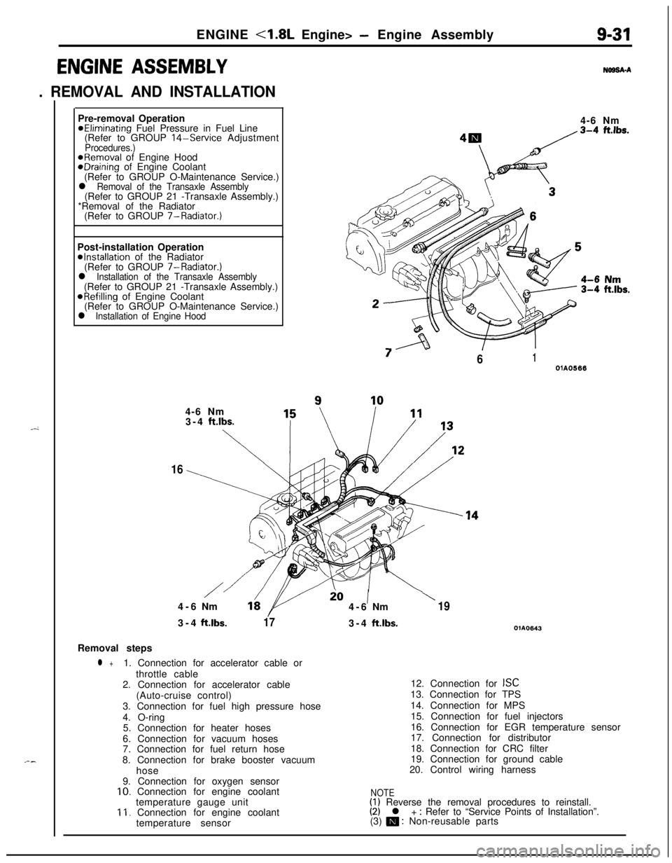
ENGINE ASSEMBLY
. REMOVAL AND INSTALLATION
N69SA-APre-removal Operation
@Eliminating Fuel Pressure in Fuel Line
(Refer to GROUP 14-Service AdjustmentProcedures.)@Removal of Engine HoodeDraining of Engine Coolant
(Refer to GROUP O-Maintenance Service.)
l Removal of the Transaxle Assembly(Refer to GROUP 21 -Transaxle Assembly.)
*Removal of the Radiator
(Refer to GROUP 7-Radiator.)
Post-installation Operation
@Installation of the Radiator
(Refer to GROUP 7-Radiator.)
l Installation of the Transaxle Assembly(Refer to GROUP 21 -Transaxle Assembly.)
@Refilling of Engine Coolant
(Refer to GROUP O-Maintenance Service.)
l Installation of Engine Hood4-6 Nm
“7
/61OlA05664-6 Nm
3-4
ft.lbs.
\
16
/io1\4-6Nm164-6Nm193-4ft.lbs.
173-4ft.lbs.OlA0643Removal steps
l +1. Connection for accelerator cable or
throttle cable
2. Connection for accelerator cable
(Auto-cruise control)
3. Connection for fuel high pressure hose
4. O-ring
5. Connection for heater hoses
6. Connection for vacuum hoses
7. Connection for fuel return hose
8. Connection for brake booster vacuum
hose
9. Connection for oxygen sensor
10. Connection for engine coolant
temperature gauge unit
11. Connection for engine coolant
temperature sensor12. Connection for
ISC13. Connection for TPS
14. Connection for MPS
15. Connection for fuel injectors
16. Connection for EGR temperature sensor
17. Connection for distributor
18. Connection for CRC filter
19. Connection for ground cable
20. Control wiring harness
NOTE(1) Reverse the removal procedures to reinstall.(2) l + : Refer to “Service Points of Installation”.
(3) m : Non-reusable parts
Page 320 of 1216
9-36ENGINE
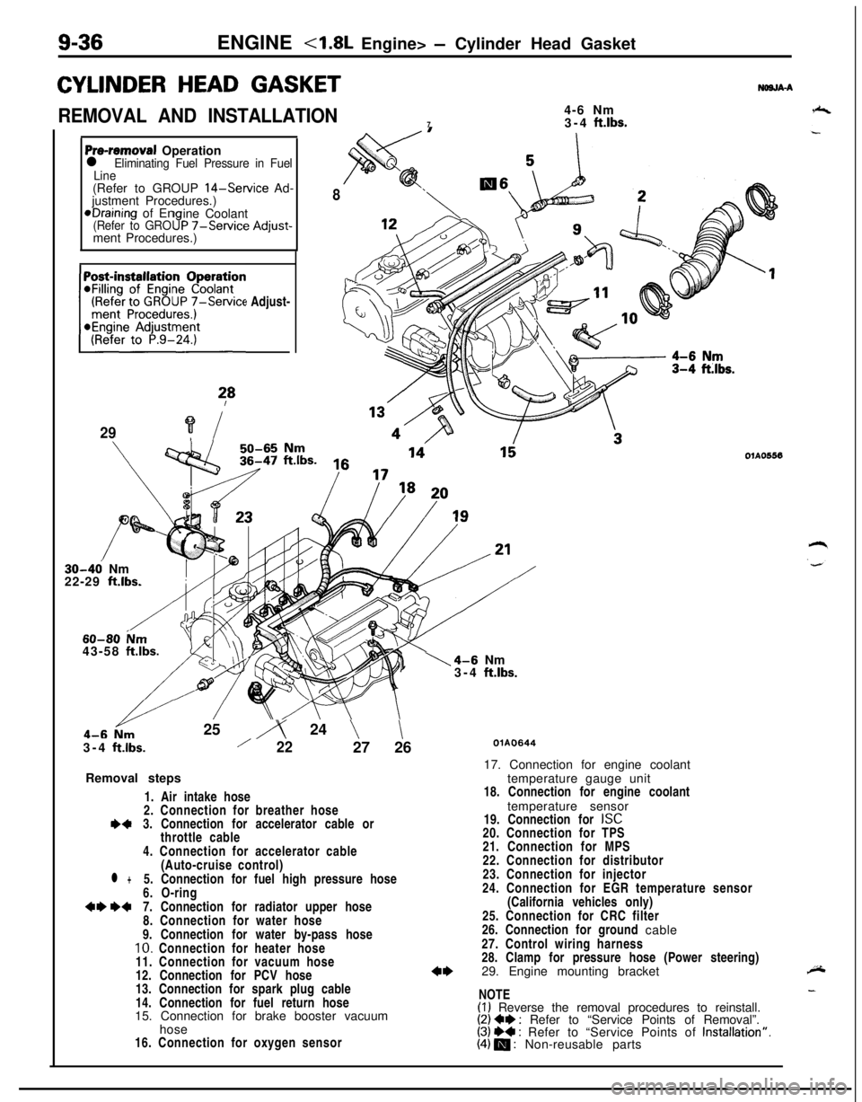
CYLINDER HEAD GASKET
REMOVAL AND INSTALLATION4-6 Nm
73-4 ft.lbs.
NWJA-A
Pre-removal Operationl Eliminating Fuel Pressure in Fuel
Line(Refer to GROUP
14-Service Ad-
justment Procedures.)*Draining of En
ine Coolant
(Refer to GRO9P -/-Service Adjust-ment Procedures.)
(Refer to GROUP
7-Service Adjust-~~~~~~~n
?*
29?i
8
30-46 Nm
22-29 ft.lbs.
60-80 ium43-58 ftlbs.25
iy 24 \\3-4
ftlbs./2227 26
Removal steps
1. Air intake hose
2. Connection for breather hose
I)43. Connection for accelerator cable or
throttle cable
4. Connection for accelerator cable
(Auto-cruise control)
l +5. Connection for fuel high pressure hose
6. O-ring
+e W7. Connection for radiator upper hose
8. Connection for water hose
9. Connection for water by-pass hose
10. Connection for heater hose
11. Connection for vacuum hose
12. Connection for PCV hose
13. Connection for spark plug cable
14. Connection for fuel return hose
15. Connection for brake booster vacuum
hose
16. Connection for oxygen sensor
1\4-6 Nm
3-4 ftlbs.
OlAO556
QlAO64417. Connection for engine coolant
temperature gauge unit
18. Connection for engine coolant
temperature sensor
19. Connection for
ISC20. Connection for TPS
21. Connection for MPS
22. Connection for distributor
23. Connection for injector
24. Connection for EGR temperature sensor
(California vehicles only)
25. Connection for CRC filter
26. Connection for ground cable
27. Control wiring harness
28. Clamp for pressure hose (Power steering)
29. Engine mounting bracket
NOTE
(I) Reverse the removal procedures to reinstall.(2) Ce : Refer to “Service Points of Removal”.(3) ++ : Refer to “Service Points of Installation”.(4) m : Non-reusable parts
Page 455 of 1216
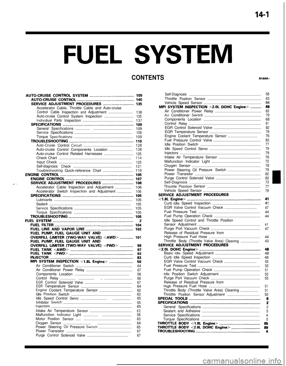
14-IFUEL SYSTEM
CONTENTS
AUTO-CRUISECONTROLSYSTEM...........................................109AUTO-CRUISECONTROL.......................................................140SERVICEADJUSTMENTPROCEDURES..............................135Accelerator Cable, Throttle Cable and Auto-cruise
ControlCableInspectionandAdjustment........................136Auto-cruise
ControlSystemInspection.............................135lndrvrdualPartsInspection..................................................137SPECIFICATIONS.....................................................................109GeneralSpecifications.......................................................109ServiceSpecifications
.........................................................109Torque Specrfications..........................................................109TROUBLESHOOTING...............................................................110Auto-CruiseControlCircurt................................................128Auto-cruise
ControlComponentsLocation........................126Auto-cruise Control Related Harnesses
.............................125Check Chart
........................................................................114Input Check.........................................................................123Self-diagnosis
Check..........................................................121Troubleshootrng
Quick-referenceChart..............................110ENGINECONTROL.......................................................................105ENGINECONTROL..................................................................107--SERVICEADJUSTMENTPROCEDURES..............................106Accelerator Cable Inspection and Adjustment..................106Accelerator Switch Inspectron and Adjustment................106SPECIFICATIONS.....................................................................105Lubricants.............................................................................105Sealant.................................................................................105ServiceSpecifications
..........................................................105TorqueSpecifications..........................................................105TROUBLESHOOTING...............................................................105FUELSYSTEM..............................................................................2FUELFILTER............................................................................104FUELLINEANDVAPORLINE..............................................102FUEL PUMP, FUEL GAUGE UNIT ANDOVERFILL LIMITER(TWO-WAY VALVE)
Switch........................................................64Air Conditioner Power Relay
..............................................67Components
Location......................................................56
ControlRelay
.................................................................66EGRControlSolenoidValve...............................................67EGRTemperatureSensor..................................................64Engine Coolant Temperature Sensor
.................................62IdlePosrtionSwitch
...........................................................63IdleSpeedControlServo
.............................
....................65InhibitorSwitch....................................................................65hjeCtOrS................................................................................65IntakeAirTemperatureSensor..........................................6’2MalfunctionlndtcatorLight
..........................................58MotorPosition
Sensor................................................63OxygenSensor
.................................................................64Power Steering 011 Pressure Swatch...........................65PowerTransistor
................................................................67PurgeControlSolenoidValve.........................................67
Self-Diagnosis.......................................................................
ThrottlePositronSensor.....................................................
Vehicle Speed Sensor.........................................................MPI
SYSTEMINSPECTION<2.0L DOHCEngine>...........Air Conditioner Power Relay..............................................
Arr Conditioner Swatch........................................................
Components Location
.........................................................
Control
Relay.......................................................................
EGR Control Solenoid Valve...............................................
EGR Temperature Sensor
...................................................
Engine Coolant Temperature Sensor
.................................Fuel Pressure Control Valve...............................................
Idle Position Switch
............................................................
Idle
SpeedControlServo...................................................Injectors
................................................................................
Intake Air Temperature Sensor..........................................
Malfunction Indicator Light.................................................
Oxygen Sensor
....................................................................
Power
Steering
OilPressureSwitch.................................Power Transistor
.................................................................
Purge Control Solenoid Valve.............................................
Self-Diaanosis.......................................................................
58
63
2382
79
688182
79
7682
77
79
79
76
727879
82
8273ThrottletiPosition Sensor
.....................................................77Vehicle Speed Sensor
.........................................................79SERVICE ADJUSTMENT PROCEDURES<1.8L Engine>........................................................................41Curb Idle Speed Inspection
................................................41EGR Valve Control Vacuum Check....................................47Fuel Pressure Test
..............................................................44Fuel Pump Operation Check
..............................................44Idle Speed Control and Throttle Position
Sensor Adjustment
..............................................................
41Purge Port Vacuum Check
.................................................47Release of Residual Pressure from
High Pressure Fuel Hose
...................................................
44Throttle
Body(Throttle Valve Area)Cleaning....................43SERVICE ADJUSTMENT PROCEDURES<2.0LDOHCEngine>............................................................48Basic Idle Speed Adjustment
.............................................
48
Curb Idle Speed Inspection
................................................48EGR Valve Control Vacuum Check....................................55Fuel Pressure Test
..............................................................52Fuel Pump Operation Check
..............................................51Idle Position Switch Adjustment........................................52Purge Port Vacuum Check
.................................................55Release of Residual Pressure from
High Pressure Fuel Hose
...................................................51Throttle Body (Throttle Valve Area) Cleaning....................51ThrottlePositionSensorAdjustment.................................50SPECIALTOOLS......................................................................6SPECIFICATIONS.....................................................................2GeneralSpecifications.........................................................2Sealant and Adhesive
.........................................................5Service Specifications
..........................................................4Torque Specifications
..........................................................5THROlTLEBODY<1.8LEngine>........................................85THROlTLE BODY <2.0L DOHC Engine>............................89TROUBLESHOOTING...............................................................6
Page 456 of 1216
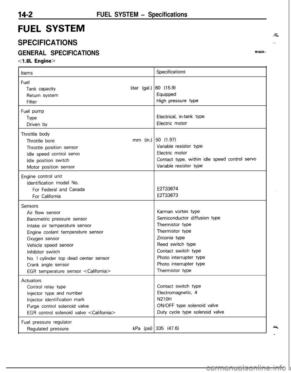
14-2FUEL SYSTEM - Specifications
FUEL SYSTEM
SPECIFICATIONS
GENERAL SPECIFICATIONSNW%-
4.8L Engine>
Items
Fuel
Tank capacity
Return system
Filter
Fuel pump
Type
Driven by
Throttle bodyThrottle
bore
Throttle position sensor
Idle speed control servo
Idle position switchMotor position
sensor
Engine control unitIdentification
model No.
For Federal and Canada
For California
SensorsAir flow
sensor
Barometric pressure sensor
Intake air temperature sensor
Engine coolant temperature sensorOxygen
sensor
Vehicle speed sensorInhibitor switch
No. 1 cylinder top dead center sensor
Crank angle sensor
EGR temperature sensor
Control relay type
Injector type and number
Injector identification mark
Purge control solenoid valve
EGR control solenoid valve
Fuel pressure regulator
Regulated pressure
Specificationsliter
(gal.) 60 (15.9)
Equipped
High pressure type
Electrical, in-tank type
Electric motor
mm (in.) 50 (1.97)
Variable resistor type
Electric motor
Contact type, within idle speed control servo
Variable resistor type
E2T33674
E2T33673
Karman vortex type
Semiconductor diffusion typeThermistor typeThermistor type
Zirconia type
Reed switch type
Contact switch type
Photo interrupter type
Photo interrupter typeThermistor type
Contact switch type
Electromagnetic, 4
N210H
ON/OFF type solenoid valveDuty
cycle type solenoid valve
kPa (psi) 335 (47.6)
Page 457 of 1216
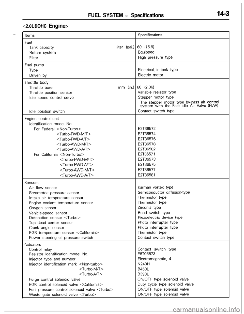
FUEL SYSTEM - Specifications14-3
<2.0L DOHC Engine>
ItemsSpecifications
Fuel
Tank capacityliter (gal.) 60 (15.9)
Return systemEquipped
FilterHigh pressure type
Fuel pump
TypeElectrical, in-tank type
Driven byElectric motor
Throttle bodyThrottle
boremm (in.) 60 (2.36)Throttle position
sensorVariable resistor type
Idle speed control servoStepper motor type
The stepper motor type by- ass air controlsystem with the Fast Idle6!rr Valve (FIAV)
Idle position switchContact switch type
Engine control unitIdentification
model No.
For Federal
E2T36574
E2T36576
E2T36578
E2T36582
For California
E2T36573
E2T36575
E2T36577
E2T36581
SensorsAir flow
sensorKarman vortex type
Barometric pressure sensorSemiconductor diffusion-type
Intake air temperature sensorThermistor type
Engine coolant temperature sensorThermistor type
Oxygen sensorZirconia type
Vehicle-speed sensorReed switch typeDetonation
sensor
Top dead center sensorPhoto interrupter type
Crank angle sensorPhoto interrupter type
EGR temperature sensor
Power steering oil pressure switchContact switch type4ctuators
Control relayContact switch type
Resistor identification model No.E8T05873
Injector type and numberElectromagnetic, 4
Injector identification mark
B450L
B390L
Purge control solenoid valveON/OFF type solenoid valve
EGR control solenoid valve
Fuel pressure control solenoid valve
gate solenoid valve