fuel filter MITSUBISHI ECLIPSE 1991 User Guide
[x] Cancel search | Manufacturer: MITSUBISHI, Model Year: 1991, Model line: ECLIPSE, Model: MITSUBISHI ECLIPSE 1991Pages: 1216, PDF Size: 67.42 MB
Page 459 of 1216
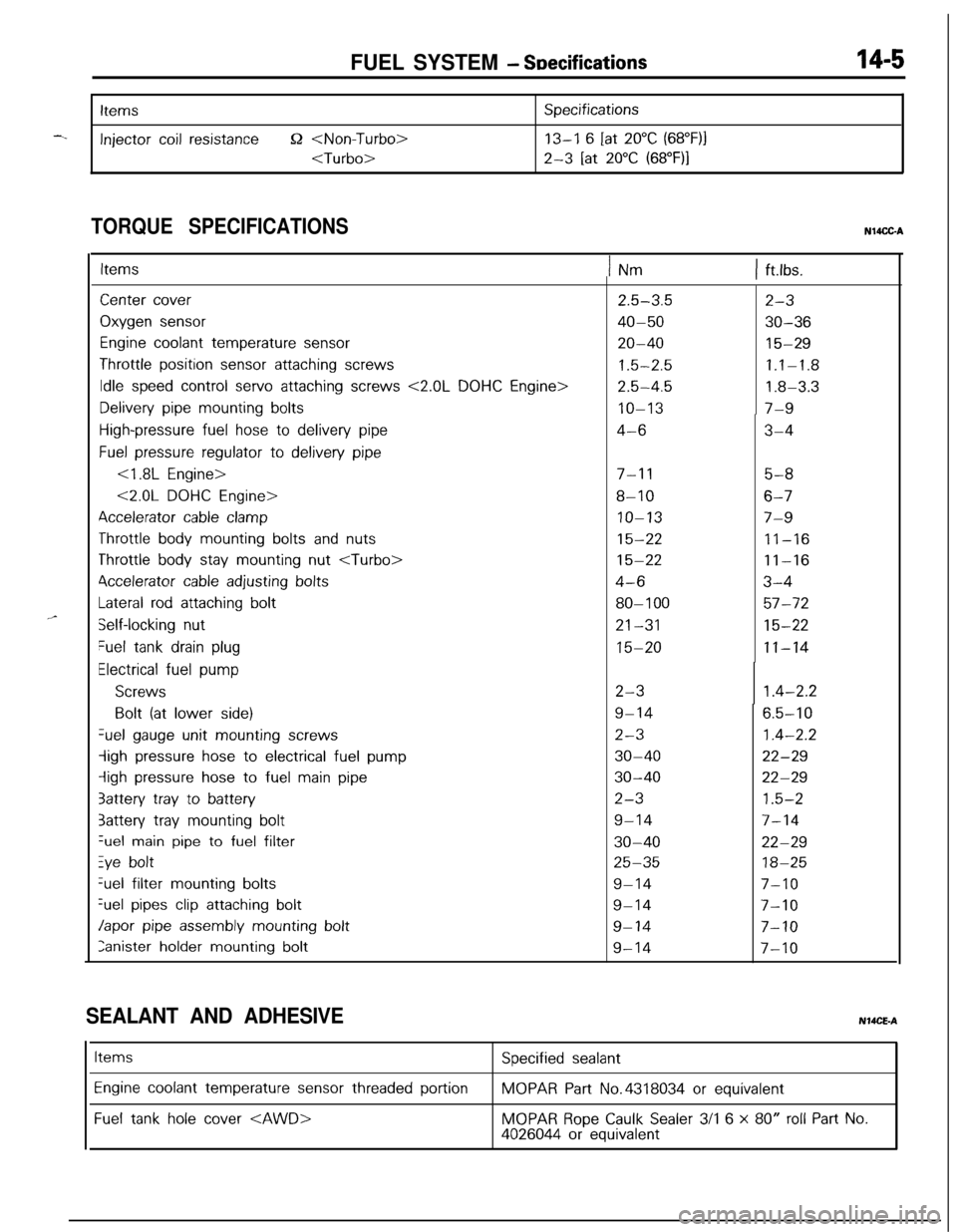
FUEL SYSTEM - SDecifications14-5
-.
Items
Injector coil resistance52
Specifications
13-I 6 [at 20°C (68”F)j
2-3 [at 20°C (68”F)I
TORQUE SPECIFICATIONSN14CC-A
,,-
ItemsINm1 ft.lbs.
Center cover
Oxygen sensor
Engine coolant temperature sensor
Throttle position sensor attaching screws
Idle speed control servo attaching screws <2.0L DOHC Engine>
Delivery pipe mounting bolts
High-pressure fuel hose to delivery pipe
Fuel pressure regulator to delivery pipe
<1.8L Engine>
<2.0L DOHC Engine>
Accelerator cable clamp
Throttle body mounting bolts and nuts
Throttle body stay mounting nut
4ccelerator cable adjusting bolts
Lateral rod attaching bolt
Self-locking nut
Fuel tank drain plug
Electrical fuel pump
Screws
Bolt (at lower side)Gel
gauge unit mounting screws
-ligh pressure hose to electrical fuel pump
iigh pressure hose to fuel main pipe
3attery tray to battery
3attery tray mounting boltGel
main pipe to fuel filter
Zye boltGel filter
mounting bolts
%el pipes clip attaching bolt
Japor pipe assembly mounting bolt
Ianister holder mounting bolt
2.5-3.5
40-50
20-40
1.5-2.5
2.5-4.5
IO-13
4-6
7-l 15-8
8-106-7
IO-137-9
15-2211-16
15-2211-16
4-63-4
80-l 0057-72
21-3115-22
15-2011-14
2-3
9-14
2-3
30-40
30-40
2-3
9-14
30-40
25-35
9-14
9-14
9-14
9-14
2-3
30-36
15-29
1.1-1.8
1.8-3.3
7-9
3-4
1.4-2.2
6.5-10
1.4-2.2
22-29
22-29
1.5-2
7-14
22-29
18-25
7-10
7-10
7-10
7-10
SEALANT AND ADHESIVENMCE-A
Items
Engine coolant temperature sensor threaded portion
Fuel tank hole cover
Specified sealant
MOPAR Part No.4318034 or equivalent
MOPAR Rope Caulk Sealer 3/l 6 x 80” roll Part No.4026044 or equivalent
Page 460 of 1216
14-6FUEL SYSTEM - Special Tools/Troubleshooting
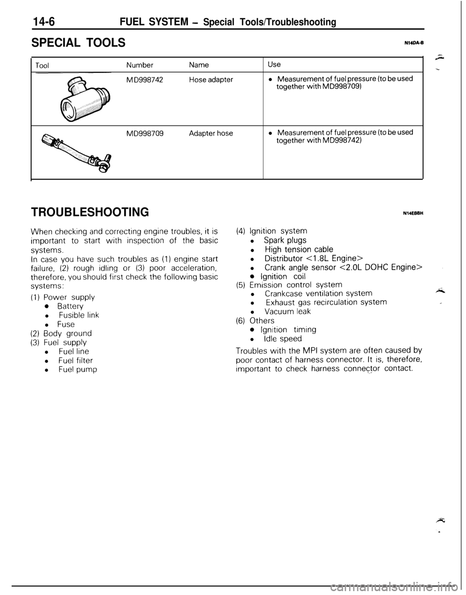
SPECIAL TOOLSNWA-B
Number
M D998742
Name
Hose adapter
Usel Measurement
of fuel pressure (to be usedtogether
with MD9987091
MD998709Adapter hosel Measurement of fuel pressure (to be usedtogether
with MD9987421
TROUBLESHOOTING
When checking and correcting engine troubles, it is
important to start with inspection of the basic
systems.
In case you have such troubles as (1) engine start
failure, (2) rough idling or (3) poor acceleration,
therefore, you should first check the following basic
systems:
(1) Power supply
0 Batteryl
Fusible linkl
Fuse
(2) Body ground
(3) Fuel supplyl
Fuel linel
Fuel filter
l
Fuel pump
N14EBBH
(4) Ignition systeml
Spark plugsl
High tension cablel Distributor
<1.8L Engine>
l
Crank angle sensor <2.0L DOHC Engine>
0 Ignition coil
(5) Emission control systeml
Crankcase ventilation systeml
Exhaust gas recirculation systeml
Vacuum leak
(6) Others
0 Ignition timing
l
Idle speed
Troubles with the MPI system are often caused by
poor contact of harness connector. It is, therefore,
important to check harness connector contact.
Page 500 of 1216
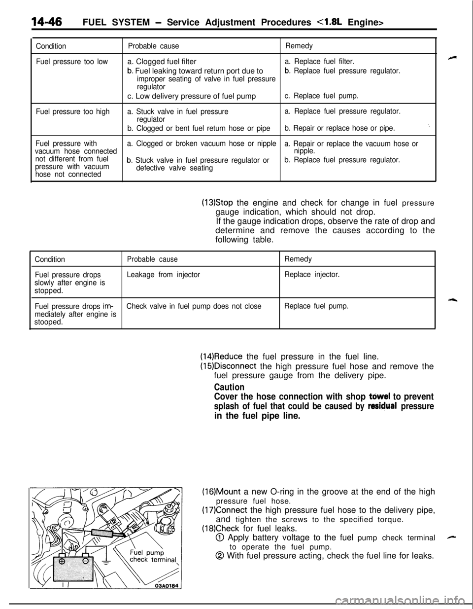
14-46FUEL SYSTEM - Service Adjustment Procedures <1.8L Engine>
Condition
Fuel pressure too low
Fuel pressure too highProbable causea. Clogged fuel filter
b. Fuel leaking toward return port due to
Remedy
a. Replace fuel filter.
improper seating of valve in fuel pressure
b. Replace fuel pressure regulator.
regulatorc. Low delivery pressure of fuel pump
c. Replace fuel pump.
a. Stuck valve in fuel pressurea. Replace fuel pressure regulator.
regulator
b. Clogged or bent fuel return hose or pipeb. Repair or replace hose or pipe.
‘.
Fuel pressure witha. Clogged or broken vacuum hose or nipple
a. Repair or replace the vacuum hose or
vacuum hose connectednipple.
not different from fuel
pressure with vacuum
b. Stuck valve in fuel pressure regulator orb. Replace fuel pressure regulator.
hose not connecteddefective valve seating
(13)Stop the engine and check for change in fuel pressure
gauge indication, which should not drop.
If the gauge indication drops, observe the rate of drop and
determine and remove the causes according to the
following table.
ConditionProbable causeRemedy
Fuel pressure dropsLeakage from injectorReplace injector.
slowly after engine is
stopped.
rqFuel pressure drops im-Check valve in fuel pump does not closeReplace fuel pump.
mediately after engine is
stooped.
(14)Reduce the fuel pressure in the fuel line.
(16)Disconnect the high pressure fuel hose and remove the
fuel pressure gauge from the delivery pipe.
Caution
Cover the hose connection with shop tdwel to prevent
splash of fuel that could be caused by residual pressure
in the fuel pipe line.
(16)Mount a new O-ring in the groove at the end of the high
pressure fuel hose.
(17)Connect the high pressure fuel hose to the delivery pipe,
and tighten the screws to the specified torque.
(18)Check for fuel leaks.
@ Apply battery voltage to the fuel pump check terminal
to operate the fuel pump.
@ With fuel pressure acting, check the fuel line for leaks.
-
Page 508 of 1216
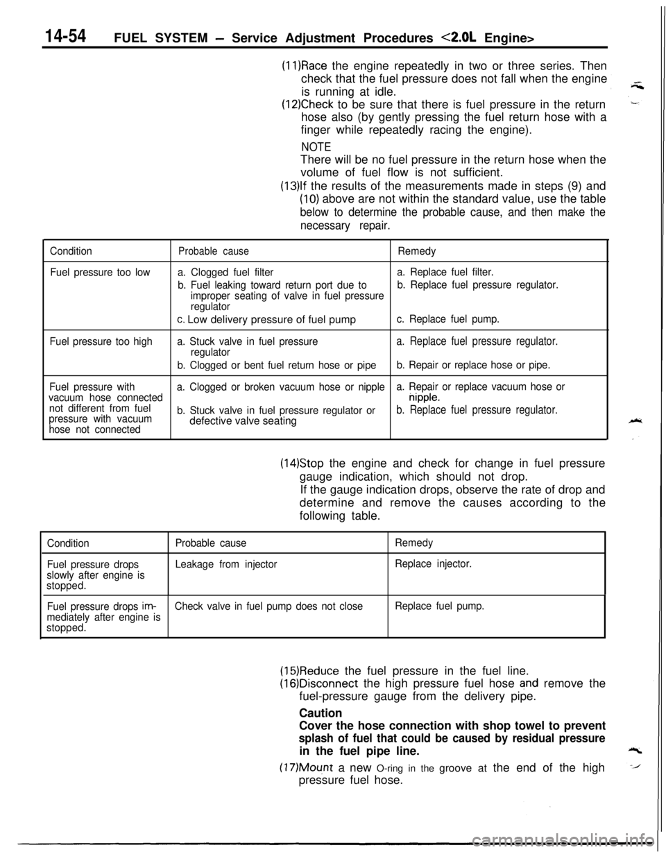
14-54FUEL SYSTEM - Service Adjustment Procedures <2.0L Engine>
(11)Race the engine repeatedly in two or three series. Then
check that the fuel pressure does not fall when the engine
is running at idle.
(12)Check to be sure that there is fuel pressure in the return
hose also (by gently pressing the fuel return hose with a
finger while repeatedly racing the engine).
NOTEThere will be no fuel pressure in the return hose when the
volume of fuel flow is not sufficient.
(13)lf the results of the measurements made in steps (9) and
(10) above are not within the standard value, use the table
below to determine the probable cause, and then make the
necessary repair.
Condition
Fuel pressure too lowProbable causeRemedy
a. Clogged fuel filtera. Replace fuel filter.
b. Fuel leaking toward return port due tob. Replace fuel pressure regulator.
improper seating of valve in fuel pressure
regulator
c. Low delivery pressure of fuel pumpc. Replace fuel pump.
Fuel pressure too higha. Stuck valve in fuel pressure
a. Replace fuel pressure regulator.regulator
b. Clogged or bent fuel return hose or pipeb. Repair or replace hose or pipe.
Fuel pressure witha. Clogged or broken vacuum hose or nipplea. Repair or replace vacuum hose or
vacuum hose connected
nipple.
not different from fuel
pressure with vacuumb. Stuck valve in fuel pressure regulator or
b. Replace fuel pressure regulator.
hose not connecteddefective valve seating
(14)Stop the engine and check for change in fuel pressure
gauge indication, which should not drop.
If the gauge indication drops, observe the rate of drop and
determine and remove the causes according to the
following table.
Condition
Fuel pressure drops
slowly after engine is
stopped.Probable cause
Leakage from injectorRemedy
Replace injector.
Fuel pressure drops
im-Check valve in fuel pump does not closeReplace fuel pump.
mediately after engine is
stopped.
(15)Reduce the fuel pressure in the fuel line.
(16)Disconnect the high pressure fuel hose and remove the
fuel-pressure gauge from the delivery pipe.
Caution
Cover the hose connection with shop towel to prevent
splash of fuel that could be caused by residual pressurein the fuel pipe line.
(17)Mount a new O-ring in the groove at the end of the high
pressure fuel hose.
Page 556 of 1216
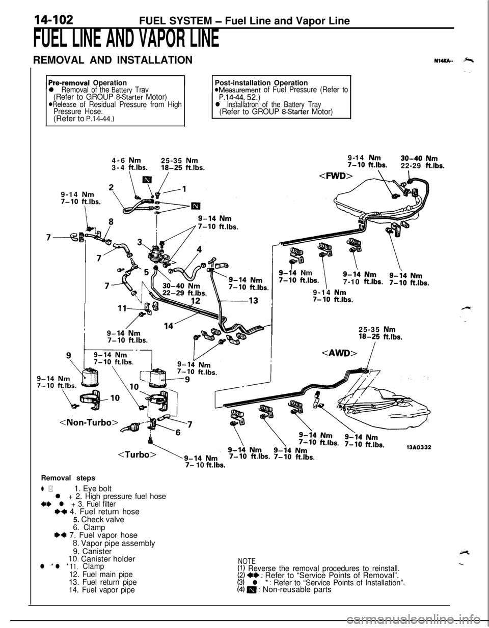
14-102FUEL SYSTEM - Fuel Line and Vapor Line
FUEL LINE AND VAPOR LINEREMOVAL AND INSTALLATION
NuKn-
rPre-removal Operationl Removal of the Batten/ Trav(Refer to GROUP 8-Starter Motor)ORelease of Residual Pressure from High
Pressure Hose.(Refer to
P.14-44.)
1Post-installation Operation*Measurement of Fuel Pressure (Refer toP.1444, 52.)l lnstallatron of the Battery Tray(Refer to GROUP 8-Starter Motor)4-6
Nm25-35 Nm3-4 ft.lbs.16-25 ftlbs.9-14 Nm7-10
ftlbs.
I
7-9-14
Nm30-40 Nm7-10 ft.lbs.22-29 ft.lbs.
9-14 Nm
7-10 ftlbs.
9-14Nm7-10 ft.lbs.9-h Nm
7-10ft.lbs.9-i4 Nm7-10ft.lbs.9-14
Nm7- 10ft.lbs.25-35
Nm16-25 ft.lbs.
7-10 ft.lbs. 7-10 ft.lbs.
7- 10 ft.lbs.Removal steps
l *1. Eye boltl + 2. High pressure fuel hose+e l + 3. Fuel filterI)+ 4. Fuel return hose
5. Check valve
6. Clamp~~ 7. Fuel vapor hose
8. Vapor pipe assembly
9. Canister
10. Canister holderl * l * 11.Clamp
12. Fuel main pipe
13. Fuel return pipe
14. Fuel vapor pipe
NOTE(I) Reverse the removal procedures to reinstall.(2) +e : Refer to “Service Points of Removal”.(3) l * : Refer to “Service Points of Installation”.(4) m : Non-reusable parts
Page 557 of 1216
-.FUEL SYSTEM
- Fuel Line pnd Vapoi- @f&
L
Mounting
bolts
pipe
03FOOO
!-03FOO7 [SERVICE. POINTS
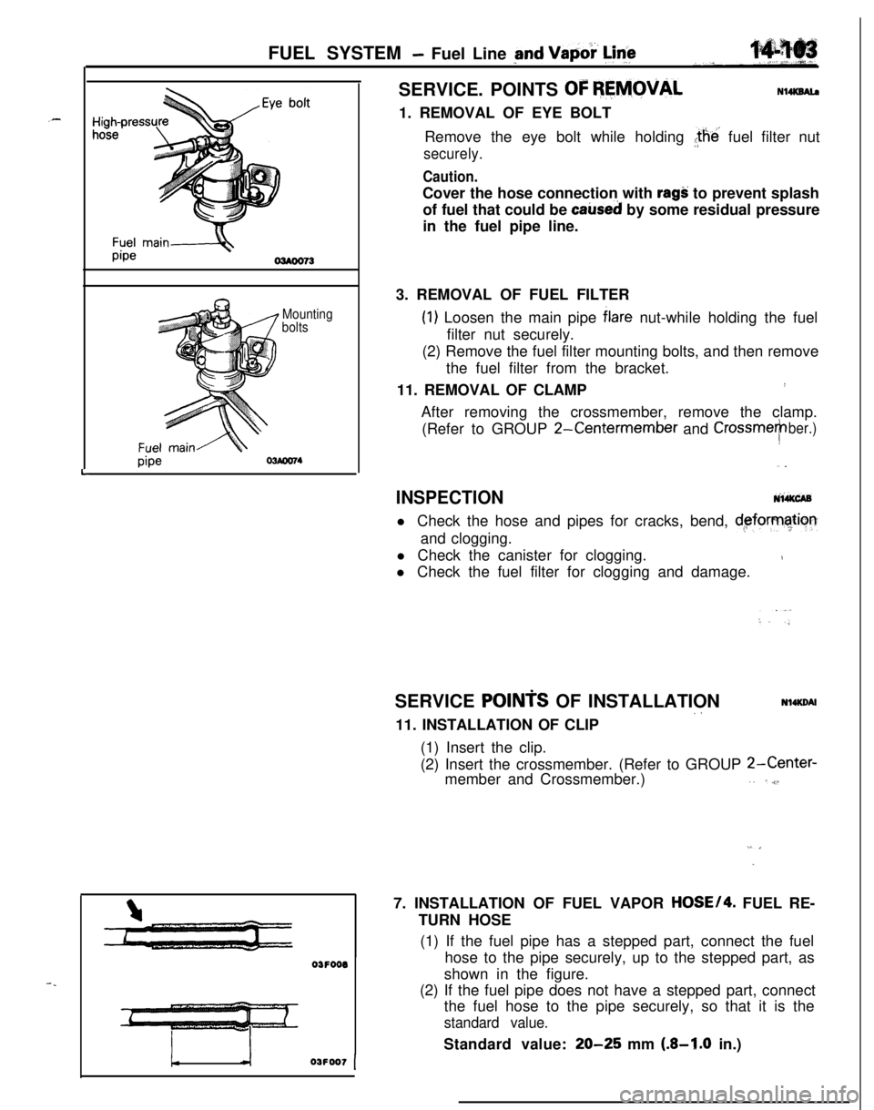
OF REMOVALN14KSAl.a1. REMOVAL OF EYE BOLT
Remove the eye bolt while holding the’ fuel filter nut
securely.
Caution.Cover the hose connection with
ragS: to prevent splash
of fuel that could be
caked by some residual pressure
in the fuel pipe line.
3. REMOVAL OF FUEL FILTER
(1) Loosen the main pipe blare nut-while holding the fuel
filter nut securely.
(2) Remove the fuel filter mounting bolts, and then remove
the fuel filter from the bracket.
11. REMOVAL OF CLAMP
!After removing the crossmember, remove the clamp.
(Refer to GROUP
2-Centermember and CrossmeTber.),.
INSPECTIONNi&CABl Check the hose and pipes for cracks, bend,
d,eforrnatiorrand clogging.
l Check the canister for clogging.
1l Check the fuel filter for clogging and damage.
SERVICE
POINTS OF INSTALLATION~aNl4KDAl11. INSTALLATION OF CLIP
(1) Insert the clip.
(2) Insert the crossmember. (Refer to GROUP
2-Center-member and Crossmember.),. ,,$l
”7. INSTALLATION OF FUEL VAPOR
HOSE/4. FUEL RE-
TURN HOSE
(1) If the fuel pipe has a stepped part, connect the fuel
hose to the pipe securely, up to the stepped part, as
shown in the figure.
(2) If the fuel pipe does not have a stepped part, connect
the fuel hose to the pipe securely, so that it is the
standard value.Standard value:
20-25 mm (.&I.0 in.)
Page 558 of 1216
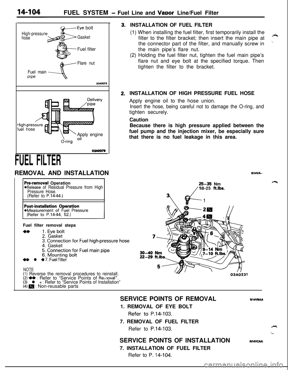
FUEL SYSTEM - Fuel Line and VaDor Line/Fuel Filter
High-pressur
hose
f+-----Eye bolt
Gasket
Fuel filter
Flare nut
Fuel main
pipe
\-Apply engine
&ring Oi’
FUEL FILTERREMOVAL AND INSTALLATION3.2.INSTALLATION OF FUEL FILTER
(1) When installing the fuel filter, first temporarily install the
filter to the filter bracket; then insert the main pipe at
‘*the connector part of the filter, and manually screw in
..the main pipe’s flare nut.
(2) Holding the fuel filter nut, tighten the fuel main pipe’s
flare nut and eye bolt at the specified torque. Then
tighten the filter to the bracket.
Pre-removal Operation@Release of Residual Pressure from High
Pressure Hose.
(Refer to P.14-44.)IIFuel filter removal steps
**1. Eye bolt2. Gasket3. Connection for Fuel high-pressure hose
4. Gasket
5. Connection for Fuel main pipe6. Mounting bolt+e l 4 7. Fuel filter
NOTE(1) Reverse the removal procedures to reinstall.(2) +e : Refer to “Service Points of Removal”.(3) l + : Refer to “Service Points of Installation”(4) m : Non-reusable partsINSTALLATION OF HIGH PRESSURE FUEL HOSE
Apply engine oil to the hose union.
Insert the hose, being careful not to damage the O-ring, andtighten securely.
Caution
Because there is high pressure applied between the
fuel pump and the injection mixer, be especially sure
that there is no fuel leakage in this area.
N14VA-25-35 Nm
18-25
ft.lbs.
vd-
7’
1
Y03A0231SERVICE POINTS OF REMOVAL
NlIVBAA1. REMOVAL OF EYE BOLT
Refer to P.14-103.
7. REMOVAL OF FUEL FILTER
Refer to
P.14-103.SERVICE POINTS OF INSTALLATION
7. INSTALLATION OF FUEL FILTER
Refer to P. 14-104.
N14VCAA