washer fluid MITSUBISHI ECLIPSE 1991 Service Manual
[x] Cancel search | Manufacturer: MITSUBISHI, Model Year: 1991, Model line: ECLIPSE, Model: MITSUBISHI ECLIPSE 1991Pages: 1216, PDF Size: 67.42 MB
Page 145 of 1216
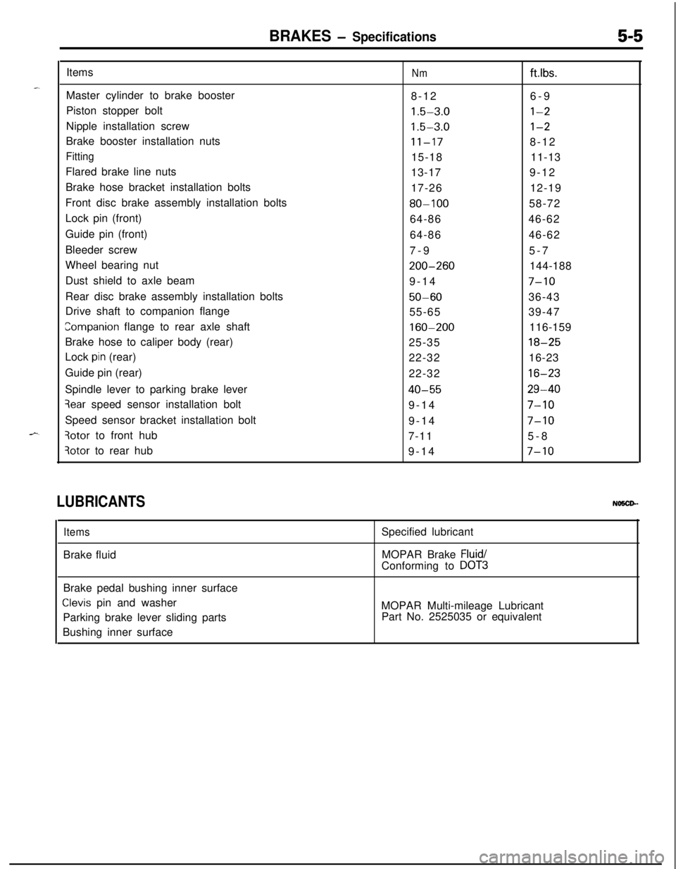
BRAKES - Specifications5-5Items
Nmftlbs.Master cylinder to brake booster
8-126-9
Piston stopper bolt
1.5-3.0l-2Nipple installation screw
1.5-3.0l-2Brake booster installation nuts
11-178-12
Fitting15-1811-13
Flared brake line nuts
13-179-12
Brake hose bracket installation bolts
17-2612-19
Front disc brake assembly installation bolts
80-10058-72
Lock pin (front)
64-8646-62
Guide pin (front)
64-8646-62
Bleeder screw
7-95-7
Wheel bearing nut
200-260144-188
Dust shield to axle beam
9-14
7-10Rear disc brake assembly installation bolts
50-6036-43
Drive shaft to companion flange
55-6539-47
companion flange to rear axle shaft160-200116-159
Brake hose to caliper body (rear)
25-35
18-25Lock
pin (rear)
22-3216-23
Guide pin (rear)
22-32
16-23Spindle lever to parking brake lever
40-5529-40
3ear speed sensor installation bolt
9-147-10Speed sensor bracket installation bolt
9-14
7-10
3otor to front hub
7-115-8
3otor to rear hub
9-147-10
LUBRICANTSNO5CP-
ItemsBrake fluidSpecified lubricant
MOPAR Brake
Fluid/Conforming to
DOT3Brake pedal bushing inner surface
Clevis pin and washer
Parking brake lever sliding parts
Bushing inner surfaceMOPAR Multi-mileage Lubricant
Part No. 2525035 or equivalent
Page 200 of 1216
5-60BRAKES - Brake Booster
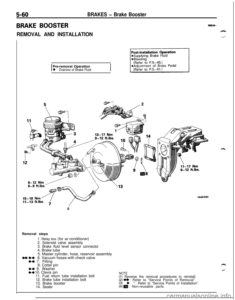
BRAKE BOOSTER
REMOVAL AND INSTALLATION
IPre-removal Operationl Drainino of Brake FluidI6
Removal steps
1. Relay box (for air conditioner)
2. Solenoid valve assembly
3. Brake fluid level sensor connector4. Brake tube
5. Master cylinder, hose, reservoir assembly
+I) e+6. Vacuum hoses with check valve+a 7. Fitting
8. Cotter pin
I)4 9. WasherI)4 10. Clevis pin11. Fuel return tube installation bolt
12. Brake tube installation bolt
13. Brake booster
14. Sealer
MA0392
NOTE(1) Reverse the removal procedures to reinstall.(2) ** : Refer to “Service Points of Removal”.(3) l * : Refer to “Service Points of Installation”.(4) m : Non-reusable parts
Page 233 of 1216
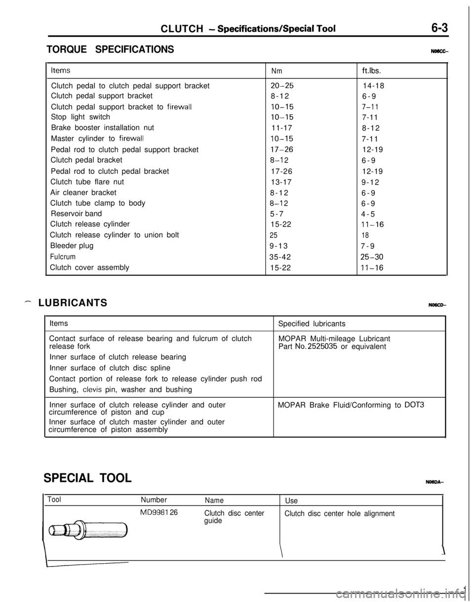
CLUTCH - Specifications/Special Tool6-3
TORQUE SPECIFICATIONSNMCC-Items
Nmftlbs.Clutch pedal to clutch pedal support bracket
20-2514-18
Clutch pedal support bracket
8-12
6-9
Clutch pedal support bracket to firewall
10-157-l 1Stop light switch
10-157-11
Brake booster installation nut
11-17
8-12
Master cylinder to firewall
10-157-11
Pedal rod to clutch pedal support bracket
17-2612-19
Clutch pedal bracket
8-l 26-9
Pedal rod to clutch pedal bracket
17-2612-19
Clutch tube flare nut
13-17
9-12
Air cleaner bracket
8-12
6-9
Clutch tube clamp to body
8-l 26-9
Reservoir band
5-7
4-5
Clutch release cylinder
15-22
11-16Clutch release cylinder to union bolt
2518Bleeder plug
9-13
7-9
Fulcrum35-4225-30Clutch cover assembly
15-22
11-16
- LUBRICANTSNOSCD-Items
Contact surface of release bearing and fulcrum of clutch
release fork
Inner surface of clutch release bearing
Inner surface of clutch disc splineSpecified lubricants
MOPAR Multi-mileage Lubricant
Part
No.2525035 or equivalent
Contact portion of release fork to release cylinder push rod
Bushing,
clevis pin, washer and bushing
Inner surface of clutch release cylinder and outer
circumference of piston and cupMOPAR Brake Fluid/Conforming to
DOT3Inner surface of clutch master cylinder and outer
circumference of piston assembly
SPECIAL TOOL
ToolNumber
MD9981 26
NameUse
Clutch disc center
guideClutch disc center hole alignment
\\
Page 239 of 1216
CLUTCH - Clutch Control6-9
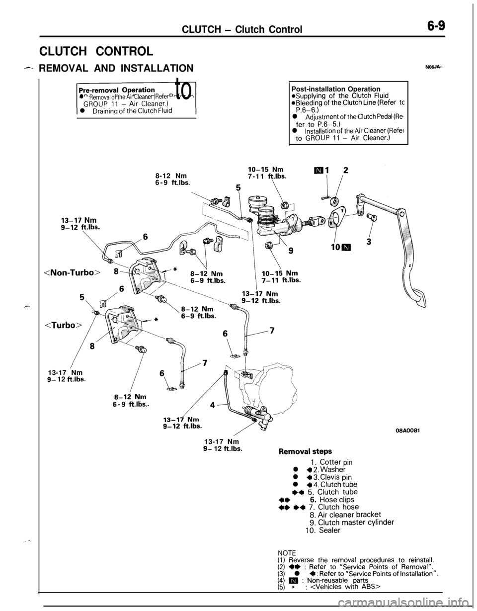
CLUTCH CONTROL
--., REMOVAL AND INSTALLATIONNOSJA-
l Removal of the Air Cleaner (Refer tol
Draining of the Clutch Fluid8-12 Nm
6-9
ftlbs.
IO-15 Nm
7-11 ft.lbs.
13-17 Nmg-12 ft.lbs.Post-installation Operation*Supplying of the
Clutch Fluid@Bleeding of the Clutch Line (Refer tCP.6-6.)l Adjustment of the Clutch Pedal (Re
fer to P.6-5.)l installation of the Air Cleaner (Refelto GROUP 11 - Air Cleaner.)
g- 12 ft.ibs.6-9
ft.lbs.
08A008113-17 Nm
9- 12 ft.lbs.Removal steps
1. Cotterpinl + 2. Washerl 4 3. Clevispinl + 4. Clutch tube~~ 5. Clutch tube
4*6. Hose clips+e I)+ 7. Clutch hose
8. Air cleaner bracket9. Clutch master cylinder10. Sealer
NOTE(1) Reverse the removal procedures to reinstall.(2) +e : Refer to “Service Points of Removal”.(3) l * : Refer to “Service Points of Installation”.I;\ m : Non-reusable, parts*:
Page 682 of 1216
19-34STEERING - Power Steering Gear Box
Guide
/Oil seal
Back-up washer13A0181
roller
13R0380
O-ring
13R037E
V&t hole
13K583-SERVICE POINTS OF REASSEMBLY
NlSPHAV
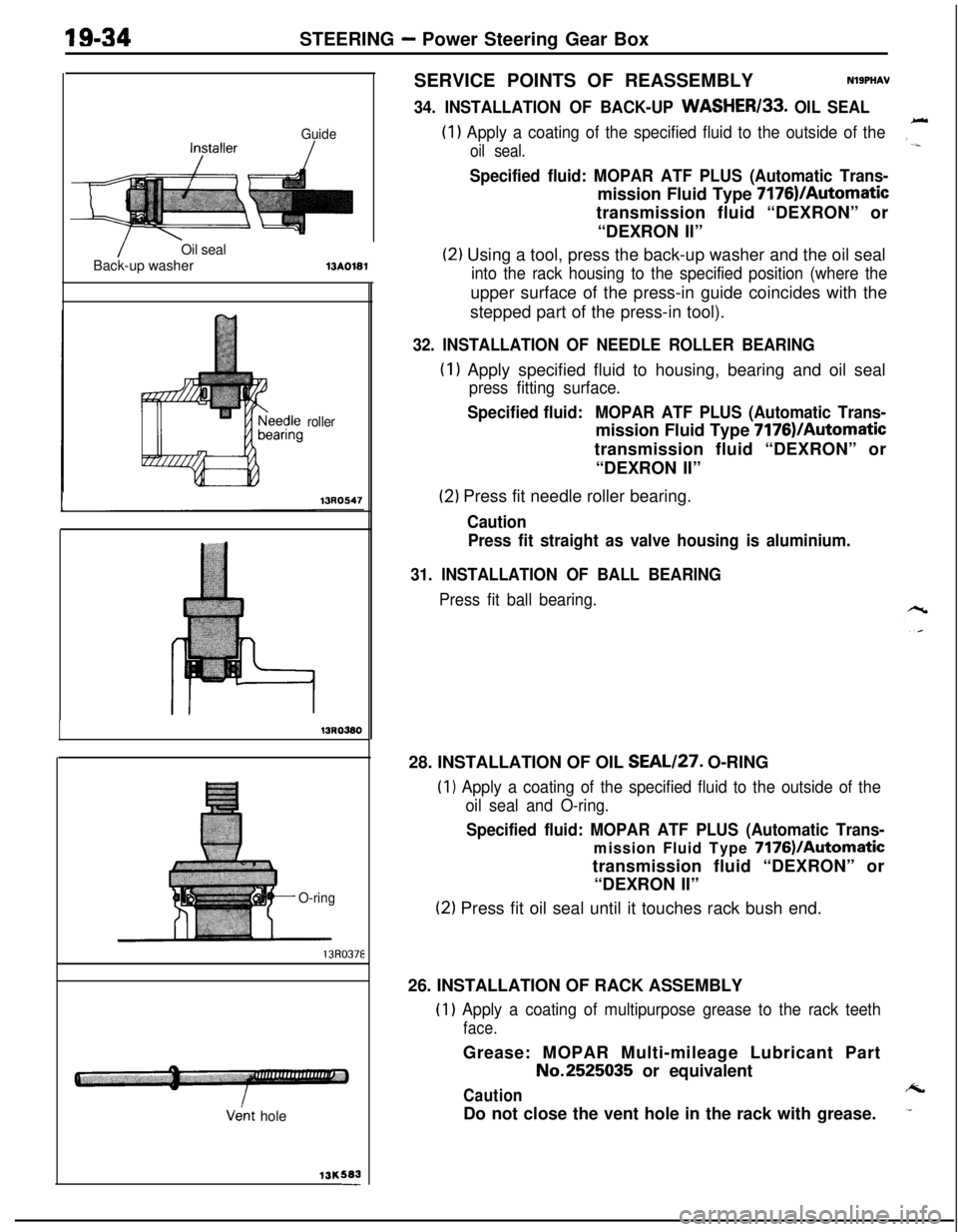
34. INSTALLATION OF BACK-UP WASHER133. OIL SEAL
(1) Apply a coating of the specified fluid to the outside of the
oil seal.
Specified fluid: MOPAR ATF PLUS (Automatic Trans-mission Fluid Type 7176)/Automatic
transmission fluid “DEXRON” or
“DEXRON II”
(2) Using a tool, press the back-up washer and the oil seal
into the rack housing to the specified position (where theupper surface of the press-in guide coincides with the
stepped part of the press-in tool).
32. INSTALLATION OF NEEDLE ROLLER BEARING
(1) Apply specified fluid to housing, bearing and oil seal
press fitting surface.
Specified fluid:MOPAR ATF PLUS (Automatic Trans-mission Fluid Type 7176)/Automatic
transmission fluid “DEXRON” or
“DEXRON II”
(2) Press fit needle roller bearing.
Caution
Press fit straight as valve housing is aluminium.
31. INSTALLATION OF BALL BEARING
Press fit ball bearing.28. INSTALLATION OF OIL SEAL/27. O-RING(I
1 Apply a coating of the specified fluid to the outside of the
oil seal and O-ring.
Specified fluid: MOPAR ATF PLUS (Automatic Trans-
mission Fluid Type 7176VAutomatictransmission fluid “DEXRON” or
“DEXRON II”
(2) Press fit oil seal until it touches rack bush end.
26. INSTALLATION OF RACK ASSEMBLY
(1) Apply a coating of multipurpose grease to the rack teeth
face.Grease: MOPAR Multi-mileage Lubricant PartNo.2525035 or equivalent
CautionDo not close the vent hole in the rack with grease.
Page 683 of 1216
STEERING - Power Steering Gear BoxOil sealMB991213
Back-up washer
13G014;
Rack bushing
7
136014813K687Seal rings
13A0110-
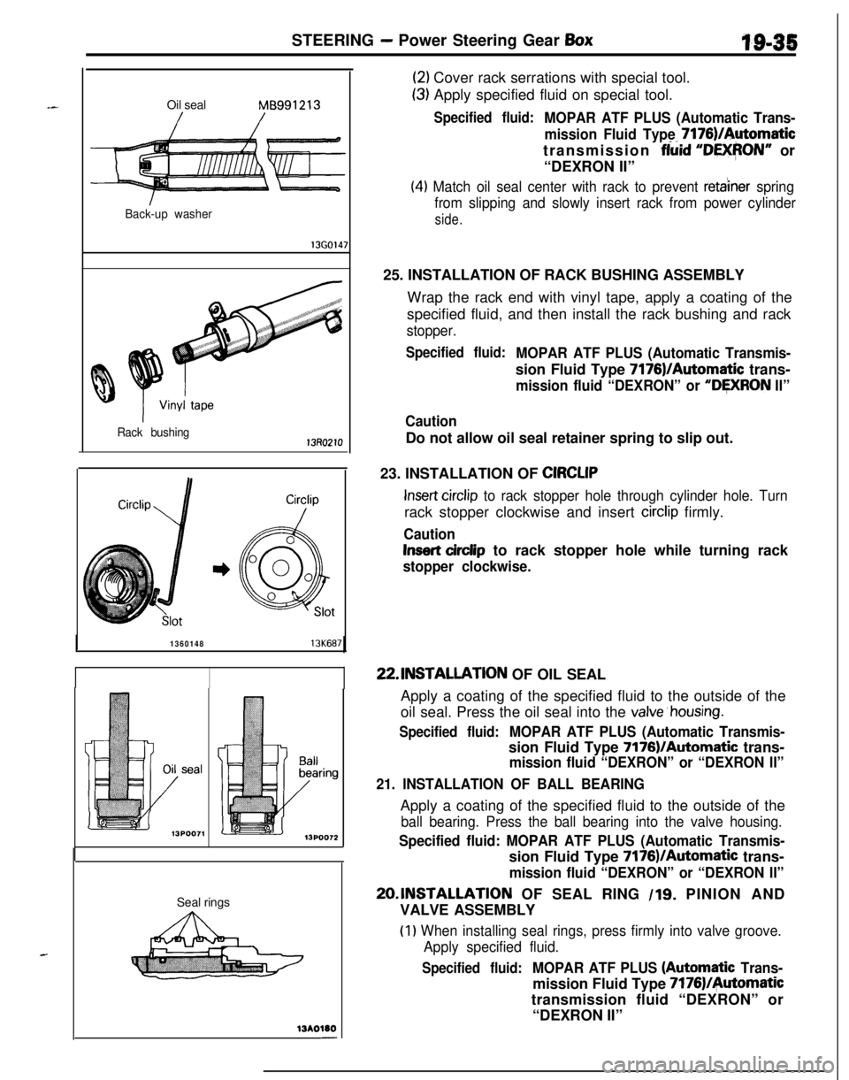
(2) Cover rack serrations with special tool.
(3) Apply specified fluid on special tool.
Specified fluid:MOPAR ATF PLUS (Automatic Trans-
mission Fluid Type 7176)/Automatic
transmission
fiiid “DEXPON” or
“DEXRON II”
(4) Match oil seal center with rack to prevent reta’iner spring
from slipping and slowly insert rack from power cylinder
side.25. INSTALLATION OF RACK BUSHING ASSEMBLY
Wrap the rack end with vinyl tape, apply a coating of the
specified fluid, and then install the rack bushing and rack
stopper.
Specified fluid:MOPAR ATF PLUS (Automatic Transmis-sion Fluid Type 7176)/Automatic trans-
mission fluid “DEXRON” or “DWRON II”
CautionDo not allow oil seal retainer spring to slip out.
23. INSTALLATION OF
CIRCLIP
Insert circlip to rack stopper hole through cylinder hole. Turnrack stopper clockwise and insert
circlip firmly.
Caution
Insert cirdip to rack stopper hole while turning rack
stopper clockwise.22.lNSTALLATlON OF OIL SEAL
Apply a coating of the specified fluid to the outside of the
oil seal. Press the oil seal into the
valve’housing.
Specified fluid:MOPAR ATF PLUS (Automatic Transmis-sion Fluid Type
7176VAutomatic trans-
mission fluid “DEXRON” or “DEXRON II”
21. INSTALLATION OF BALL BEARINGApply a coating of the specified fluid to the outside of the
ball bearing. Press the ball bearing into the valve housing.
Specified fluid: MOPAR ATF PLUS (Automatic Transmis-sion Fluid Type 7176)/Automatic trans-
mission fluid “DEXRON” or “DEXRON II”
20,lNSTALLATlON OF SEAL RING /lg. PINION AND
VALVE ASSEMBLY
(1) When installing seal rings, press firmly into valve groove.
Apply specified fluid.
Specified fluid:MOPAR ATF PLUS (Autombtic Trans-mission Fluid Type
7176)/+tomatictransmission fluid “DEXRON” or
“DEXRON II”
Page 948 of 1216
AUTOMATIC TRANSAXLE - Transaxle Assemblv
Solder
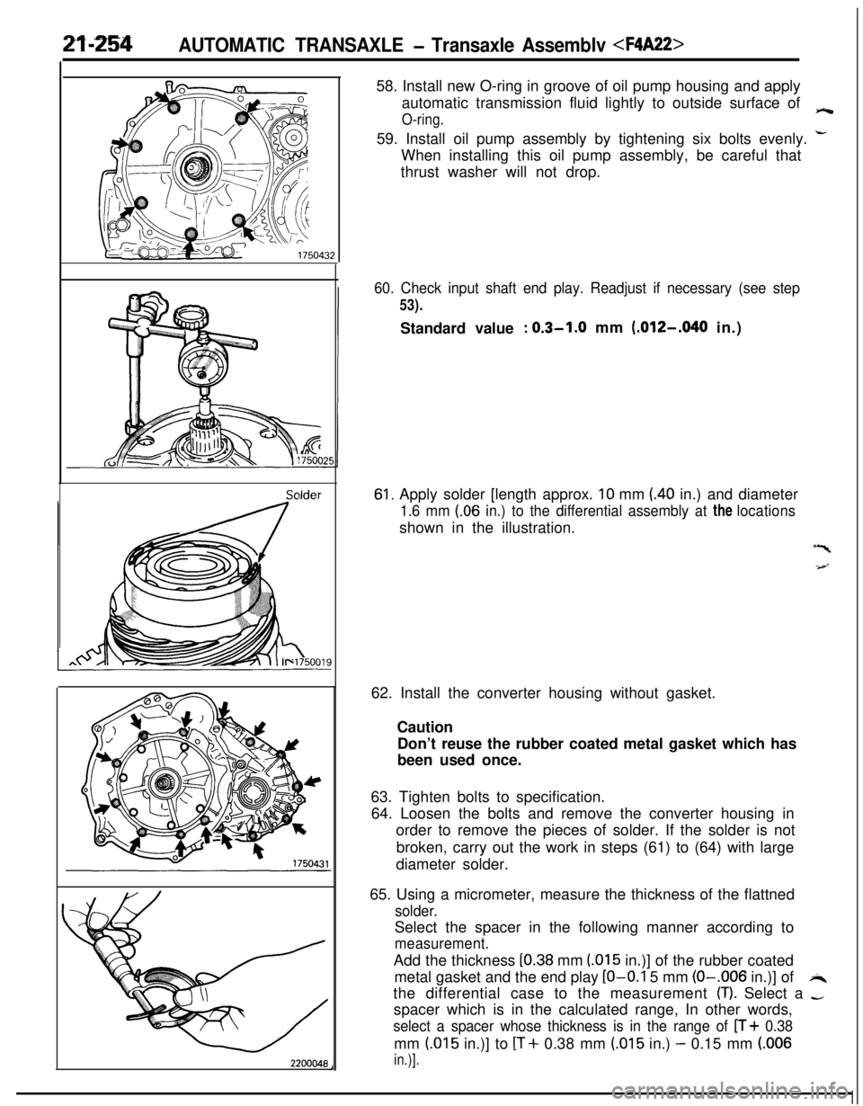
220004858. Install new O-ring in groove of oil pump housing and apply
automatic transmission fluid lightly to outside surface of
O-ring.e59. Install oil pump assembly by tightening six bolts evenly.
i-When installing this oil pump assembly, be careful that
thrust washer will not drop.
60. Check input shaft end play. Readjust if necessary (see step
53).Standard value
: 0.3-1.0 mm (.012-,040 in.)
61, Apply solder [length approx. 10 mm (40 in.) and diameter
1.6 mm (.06 in.) to the differential assembly at the locationsshown in the illustration.
“I
-4--J62. Install the converter housing without gasket.
Caution
Don’t reuse the rubber coated metal gasket which has
been used once.
63. Tighten bolts to specification.
64. Loosen the bolts and remove the converter housing in
order to remove the pieces of solder. If the solder is not
broken, carry out the work in steps (61) to (64) with large
diameter solder.
65. Using a micrometer, measure the thickness of the flattned
solder.Select the spacer in the following manner according to
measurement.Add the thickness
[0.38 mm (015 in.)] of the rubber coated
metal gasket and the end play
LO-O.1 5 mm (O-.006 in.)] ofi4the differential case to the measurement
(T). Select a -spacer which is in the calculated range, In other words,
select a spacer whose thickness is in the range of n+ 0.38mm
(.015 in.)] to [T+ 0.38 mm (.015 in.) - 0.15 mm (.006
in.)].