glove box MITSUBISHI ECLIPSE 1991 Service Manual
[x] Cancel search | Manufacturer: MITSUBISHI, Model Year: 1991, Model line: ECLIPSE, Model: MITSUBISHI ECLIPSE 1991Pages: 1216, PDF Size: 67.42 MB
Page 1124 of 1216
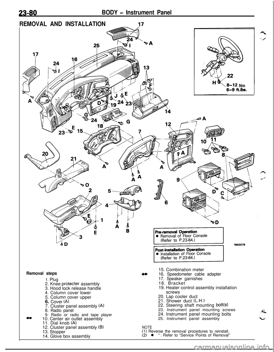
23-80BODY - Instrument Panel
REMOVAL AND INSTALLATION
-?7
Removal steps
1. Plug2. Knee protecter assembly
3. Hood lock release handle
4. Column cover lower
5. Column cover upper
6. Cover
(A)7. Cluster panel assembly (A)8. Radio panel9. Radio or radio and tape player
10. Center air outlet assembly
11. Dial knob (A)12. Cluster panel assembly (B)13. Stopper
14. Glove box assembly
Nm6-9 ft.lk.15. Combination meter
16. Speedometer cable adapter
17. Speaker garnishes18. Bracket
19. Heater control assembly installation
screws
20. Lap cooler duct
21. Shower duct (L.H.122. Steering shaft mounting bolt(s)23. Instrument panel mounting screws
24. Instrument panel mounting bolts
25. Instrument panel assembly
NOTE(1) Reverse the removal procedures to reinstall.(2) l * : Refer to “Service Points of Removal”
Page 1126 of 1216
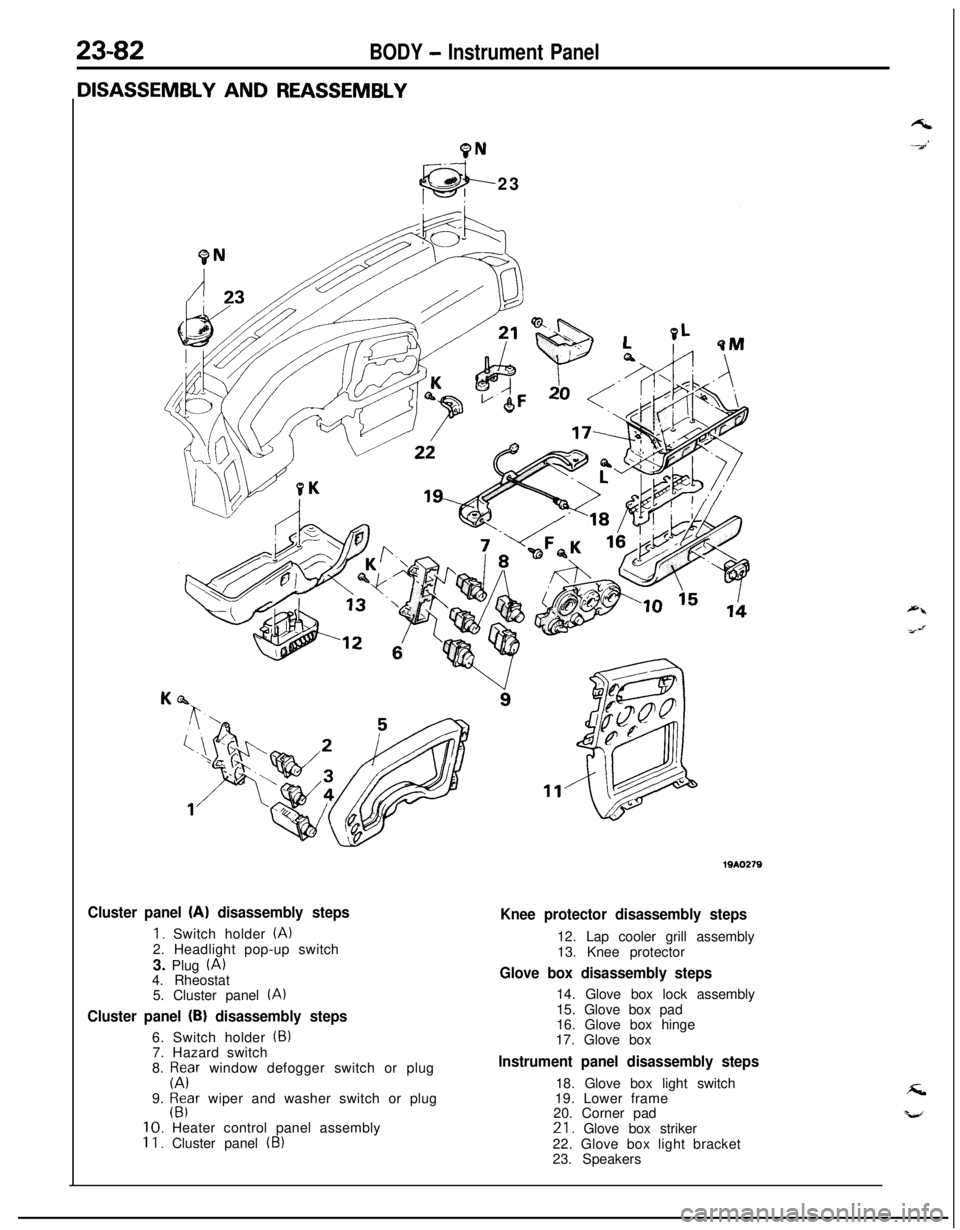
23-82BODY - Instrument Panel
9N23
Cluster panel (A) disassembly steps
1. Switch holder (A)2. Headlight pop-up switch
3. Plug
(A)4. Rheostat
5. Cluster panel
(A)
Cluster panel (B) disassembly steps6. Switch holder
(5)7. Hazard switch
8.
p;Fr window defogger switch or plug
9.
$far wiper and washer switch or plug10. Heater control panel assembly
II. Cluster panel (B)
Knee protector disassembly steps12. Lap cooler grill assembly
13. Knee protector
Glove box disassembly steps14. Glove box lock assembly
15. Glove box pad
16. Glove box hinge
17. Glove box
Instrument panel disassembly steps18. Glove box light switch
19. Lower frame
20. Corner pad21. Glove box striker
22. Glove box light bracket
23. Speakers
Page 1170 of 1216
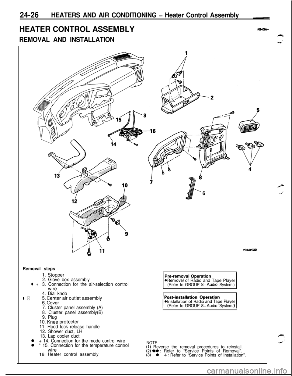
24-26HEATERS AND AIR CONDITIONING - Heater Control AssemblyHEATER CONTROL ASSEMBLY
REMOVAL AND INSTALLATIONRemoval steps
1. Stopper2. Glove box assemblyl +3. Connection for the air-selection controlwire
4. Dial knob
l *;: CI.Z;Er air outlet assembly
7. Cluster panel assembly (A)
8. Cluster panel assembly(B)
9. Plug
10. Knee protecter11. Hood lock release handle
12. Shower duct, LH
13. Lap cooler duct
l + 14. Connection for the mode control wire
l * 15. Connection for the temperature controlwire
16. Heater control assembly4
6
2OAO430Pre-removal Operation
@Removal of Radio and Tape Player(Refer to GROUP 8-Audio System.)
(Refer to GROUP
8-Audio System.)
NOTE(1) Reverse the removal procedures to reinstall.(2) 4e : Refer to “Service Points of Removal”.(3) l 4 : Refer to “Service Points of Installation”.
Page 1173 of 1216
HEATERS AND AIR CONDITIONING - Resistor
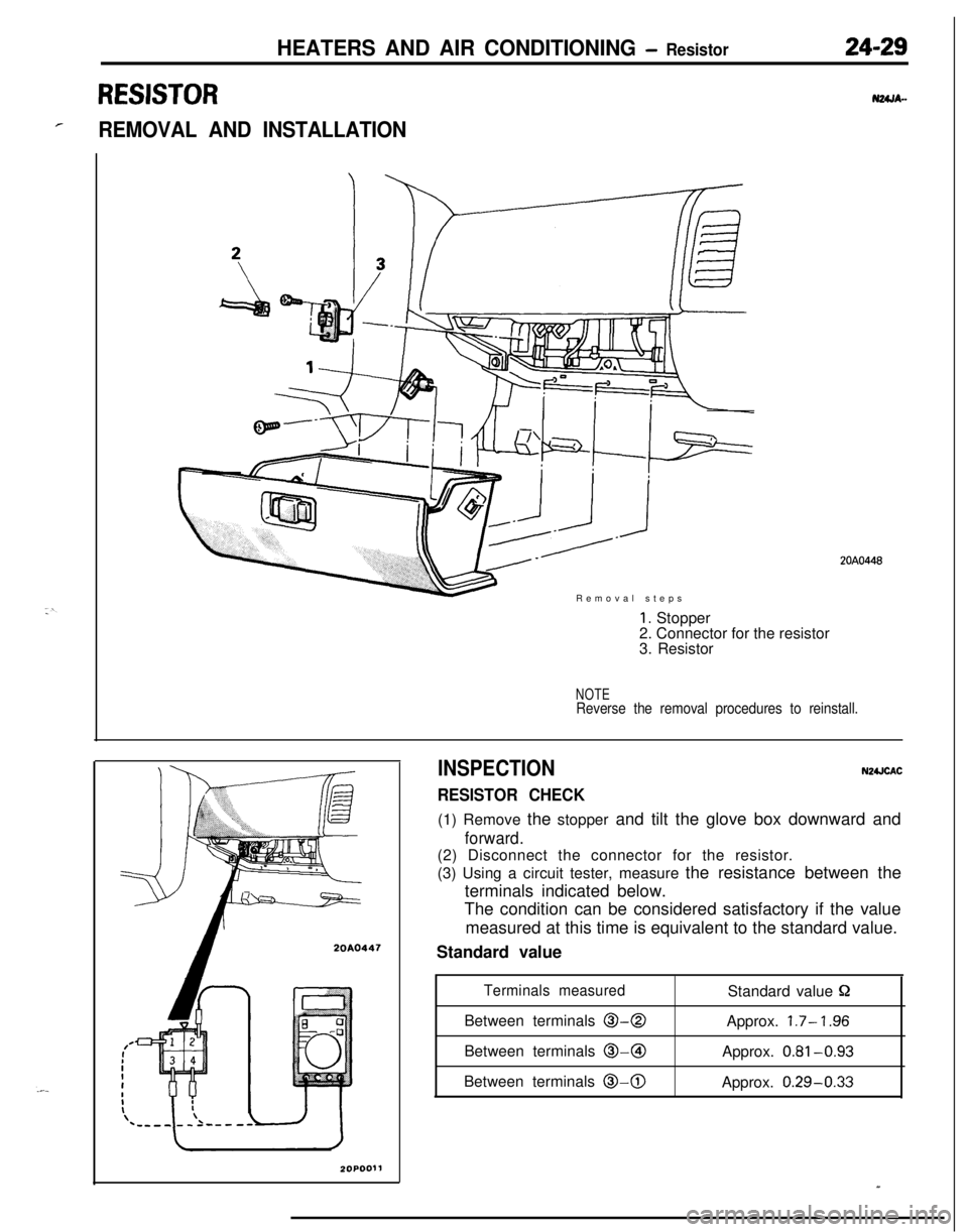
RESISTOR
rREMOVAL AND INSTALLATIONRemoval steps
20A0447
1. Stopper
2. Connector for the resistor
3. Resistor
NOTEReverse the removal procedures to reinstall.
INSPECTION
RESISTOR CHECK
N2UCAC(1) Remove the stopper and tilt the glove box downward and
forward.(2) Disconnect the connector for the resistor.
(3) Using a circuit tester, measure the resistance between the
terminals indicated below.
The condition can be considered satisfactory if the value
measured at this time is equivalent to the standard value.
Standard value
Terminals measuredStandard value PBetween terminals
O-0Approx. 1.7- ‘I .96Between terminals @-@I
Approx.
0.81-0.93Between terminals
0-0Approx. 0.29-0.33
20A0448
Page 1178 of 1216
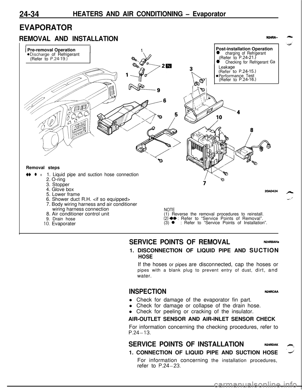
24-34HEATERS AND AIR CONDITIONING - Evaporator
EVAPORATOR
REMOVAL AND INSTALLATION
1 Pre-removal Operation1aDischarge of Refrigerant
(Refer to P.24.19.)Post-installation Operation
l charging of Refrigerant(Refer to P.24-21.)l Checking for Refrigerant Ga:(Refer to
P.24-16.)Removal steps
N l +1. Liquid pipe and suction hose connection2. O-ring
3. Stopper
4. Glove box
5. Lower frame
6. Shower duct R.H.
7. Body wiring harness and air conditioner
wiring harness connection
8. Air conditioner control unit
9. Drain hose
10. Evaporater
2OAO424
NOTE(1) Reverse the removal procedures to reinstall.
(2) ++ : Refer to “Service Points of Removal”.
(3) l : Refer to “Service Points of Installation”.
SERVICE POINTS OF REMOVALN24RBAHa1. DISCONNECTION OF LIQUID PIPE AND SUCTION
HOSEIf the hoses or pipes are disconnected, cap the hoses or
pipes with a blank plug to prevent entry of dust, dirt, and
water.
INSPECTIONN24RCAAl Check for damage of the evaporator fin part.
l Check for damage or collapse of the drain hose.
l Check for peeling or cracking of the insulator.
AIR-OUTLET SENSOR AND AIR-INLET SENSOR CHECK
For information concerning the checking procedures, refer to
P.24-13.
SERVICE POINTS OF INSTALLATIONN24RDAK1. CONNECTION OF LIQUID PIPE AND SUCTION HOSE
For information concerning the installation procedures,
refer to
P.24-23.