radiator MITSUBISHI ECLIPSE 1991 Service Manual
[x] Cancel search | Manufacturer: MITSUBISHI, Model Year: 1991, Model line: ECLIPSE, Model: MITSUBISHI ECLIPSE 1991Pages: 1216, PDF Size: 67.42 MB
Page 46 of 1216
LUBRICATION AND MAINTENANCE - Maintenance Service
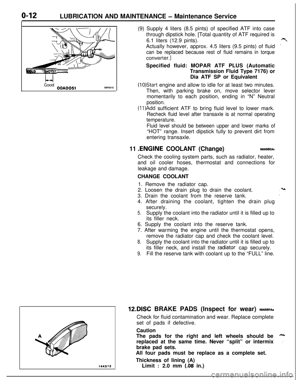
L-4GoodOOA0051C9FW1014K512(9) Supply 4 liters (8.5 pints) of specified ATF into case
through dipstick hole. [Total quantity of ATF required is
6.1 liters (12.9 pints).
Actually however, approx. 4.5 liters (9.5 pints) of fluid
can be replaced because rest of fluid remains in torque
converter.]Specified fluid: MOPAR ATF PLUS (Automatic
Transmission Fluid Type 7176) or
Dia ATF SP or Equivalent
(10)Start engine and allow to idle for at least two minutes.
Then, with parking brake on, move selector lever
momentarily to each position, ending in “N” Neutral
position.
(1 l)Add sufficient ATF to bring fluid level to lower mark.
Recheck fluid level after transaxle is at normal operating
temperature.
Fluid level should be between upper and lower marks of“HOT” range. Insert dipstick fully to prevent dirt from
entering transaxle.
11 .ENGINE COOLANT (Change)NOOSBEAcCheck the cooling system parts, such as radiator, heater,
and oil cooler hoses, thermostat and connections for
leakage and damage.
CHANGE COOLANT
1. Remove the radiator cap.
2. Loosen the drain plug to drain the coolant.
3. Drain the coolant from the reserve tank.
4. After draining the coolant, tighten the drain plug
securely.
5.Supply the coolant into the radiator until it is filled up to
its filler neck.
6. Supply the coolant into the reserve tank.
7. After warming the engine until the thermostat opens,
remove the radiator cap and check the coolant level.
8.Supply the coolant into the radiator until it is filled up to
its filler neck, and install the
.radiator, cap securely.
9.Fill the reserve tank with coolant up to the “FULL” line.12DISC BRAKE PADS (Inspect for wear)
NOOSBFA~Check for fluid contamination and wear. Replace complete
set of pads if defective.
Caution
The pads for the right and left wheels should be
replaced at the same time. Never “split” or intermix
brake pad sets.
All four pads must be replace as a complete set.
Thickness of lining (A)
Limit
:2.0 mm (.08 in.)
Page 249 of 1216
7-l
COOLING
CONTENTS
ENGINE COOLANT TEMPERATURE GAUGEUNIT,
ENGINE COOLANT TEMPERATURE
SENSOR AND ENGINE COOLANT
TEMPERATURE SWITCH................................34
RADIATOR.......................................................12
RADIATORFANMOTOR ASSEMBLY..........15
SERVICE ADJUSTMENT PROCEDURES.......8
Alternatormater Pump Drive Belt Tension
Adjustment
....................................................9Alternator/Water Pump Drive Belt Tension
Inspection..
....................................................8Cap Pressure Test
.......................................8Engine Coolant Concentration Test
.............8
EngineCoolantLeakCheck........................8Engine Coolant Replacement
.......................8
SPECIFICATIONS.............................................2
GeneralSpecifications..................................2
Lubricant.......................................................4
Sealant..........................................................4Service Specifications
...................................2Torque Specifications
...................................3THERMOSTAT
.................................................15
TROUBLESHOOTING......................................5
Noriseintemperature................................5
Overheat.......................................................5
WATER HOSE AND WATER PIPE
<1.8L Engine>................................................25
WATER HOSE AND WATER PIPE
<2.0LDOHCEngine(Non-Turbo)>.............28
WATER HOSE AND WATER PIPE
<2.0LDOHCEngine(Turbo)>....................31
WATERPUMP<1.8LEngine>.....................17
WATER PUMP <2.0L DOHC Engine>.........21
Page 250 of 1216
7-2COOLING - Specifications
SPECIFICATIONS
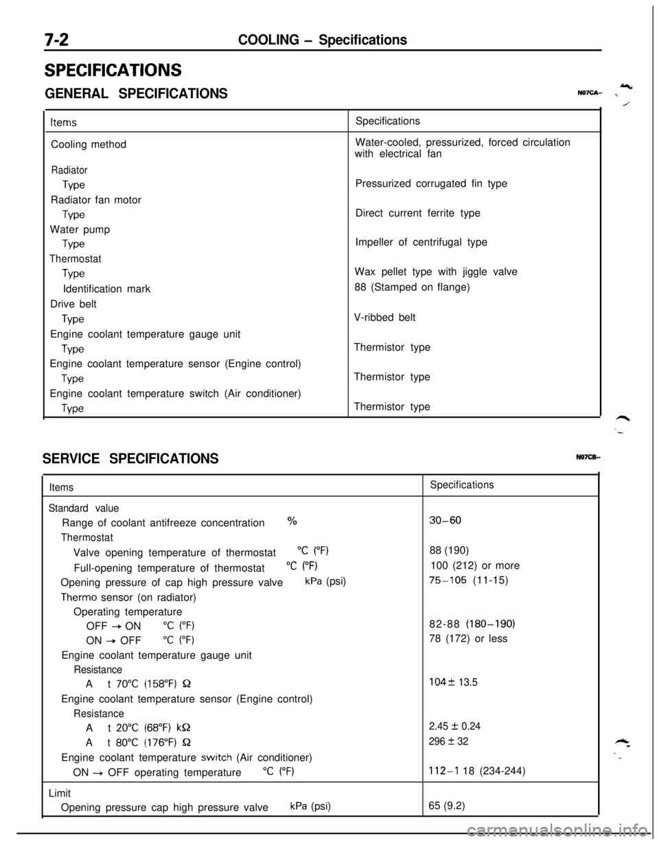
GENERAL SPECIFICATIONSIcNQ7cA- I
ItemsCooling method
Radiator
TypeRadiator fan motor
TypeWater pump
Type
Thermostat
TypeIdentification mark
Drive belt
TypeEngine coolant temperature gauge unit
WeEngine coolant temperature sensor (Engine control)
TypeEngine coolant temperature switch (Air conditioner)
WeSpecifications
Water-cooled, pressurized, forced circulation
with electrical fan
Pressurized corrugated fin type
Direct current ferrite type
Impeller of centrifugal type
Wax pellet type with jiggle valve
88 (Stamped on flange)
V-ribbed belt
Thermistor type
Thermistor type
Thermistor type
SERVICE SPECIFICATIONSN07CB.-
Items
Standard valueRange of coolant antifreeze concentration
%
ThermostatValve opening temperature of thermostat
“C (“F)Full-opening temperature of thermostat
“C (“F)Opening pressure of cap high pressure valve
kPa (psi)
Therm0 sensor (on radiator)
Operating temperature
OFF
+ ON“C (“F)ON
--P OFF“C (“F)Engine coolant temperature gauge unit
ResistanceAt
70°C (158°F) QEngine coolant temperature sensor (Engine control)
ResistanceAt
20°C (68°F) kQAt
80°C (176°F) QEngine coolant temperature
switch (Air conditioner)
ON -+ OFF operating temperature
“C (“F)Limit
Opening pressure cap high pressure valve
kPa (psi)
Specifications
30-6088 (190)
100 (212) or more
75-105 (11-15)
82-88 (180-190)
78 (172) or less
104f 13.5
2.45
I!I 0.24
296
+ 32
112-l 18 (234-244)
65 (9.2)
Page 251 of 1216
COOLING - Specifications7-3
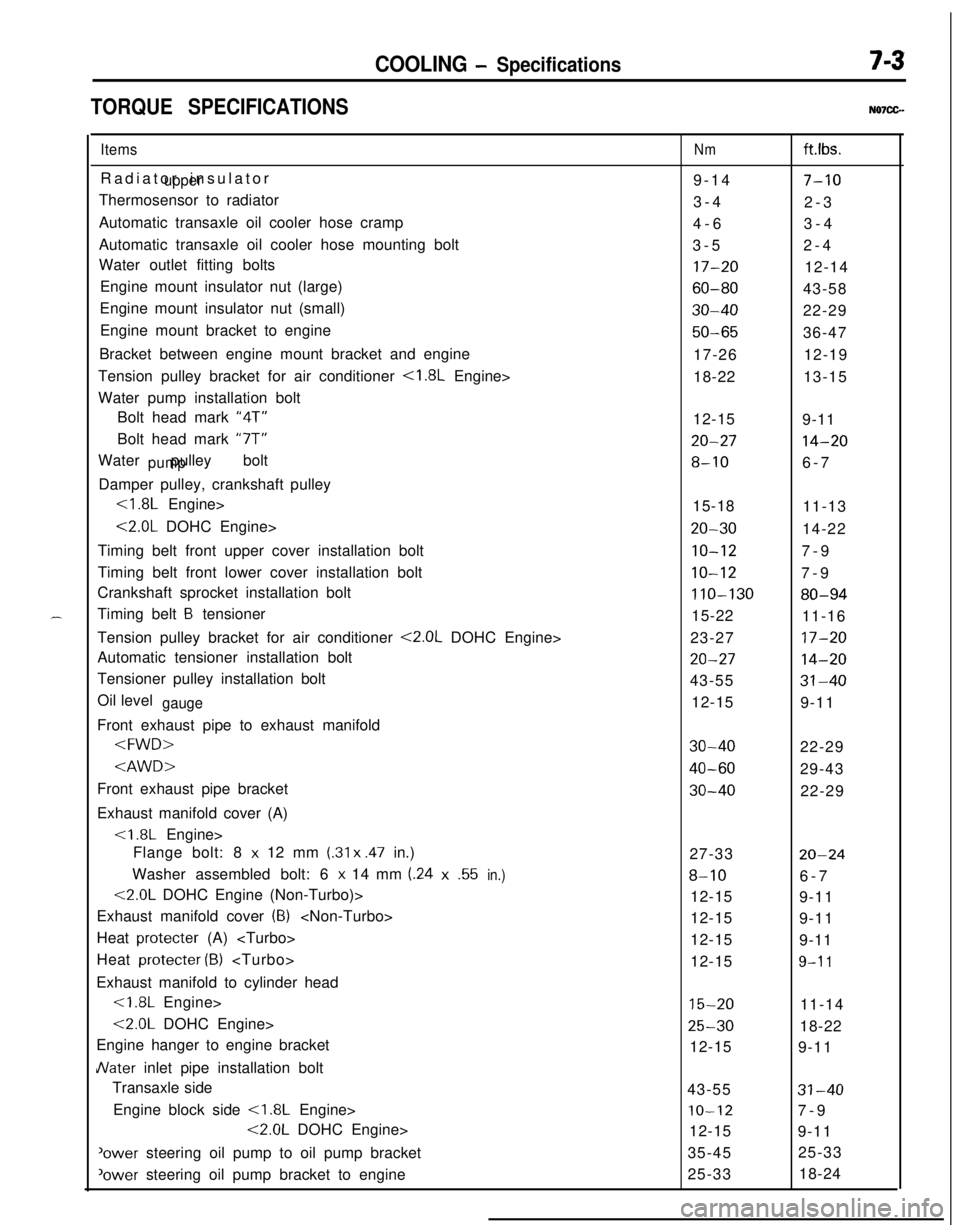
TORQUE SPECIFICATIONSN07CG.
ItemsRadiator insulator
upperThermosensor to radiator
Automatic transaxle oil cooler hose cramp
Automatic transaxle oil cooler hose mounting bolt
Water outlet fitting bolts
Engine mount insulator nut (large)
Engine mount insulator nut (small)
Engine mount bracket to engine
Bracket between engine mount bracket and engine
Tension pulley bracket for air conditioner
<1.8L Engine>
Water pump installation bolt
Bolt head mark “4T”
Bolt head mark “7T”
Water pulley bolt
pumpDamper pulley, crankshaft pulley
<1.8L Engine>
<2.0L DOHC Engine>
Timing belt front upper cover installation bolt
Timing belt front lower cover installation bolt
Crankshaft sprocket installation bolt
Timing belt
B tensioner
Tension pulley bracket for air conditioner
<2.0L DOHC Engine>
Automatic tensioner installation bolt
Tensioner pulley installation bolt
Oil level
gaugeFront exhaust pipe to exhaust manifold
Exhaust manifold cover (A)
Flange bolt: 8
x 12 mm (.31 x .47 in.)
Washer assembled bolt: 6
x 14 mm (.24x.55in.)
<2.0L DOHC Engine (Non-Turbo)>
Exhaust manifold cover
(8)
Heat protecter (A)
Heat protecter
(B)
Exhaust manifold to cylinder head<1.8L Engine>
<2.0L DOHC Engine>
Engine hanger to engine bracket
JVater inlet pipe installation bolt
Transaxle side
Engine block side
<1.8L Engine>
<2.0L DOHC Engine>
'ower steering oil pump to oil pump bracket
‘ower steering oil pump bracket to engine
Nmft.lbs.
9-14
7-103-4
2-3
4-63-4
3-52-4
17-2012-14
60-8043-58
30-4022-29
50-6536-47
17-2612-19
18-2213-15
12-15
9-11
20-2714-20
8-106-7
15-18
11-13
20-3014-22
IO-127-9
10-127-9
110-13080-9415-22
11-16
23-27
17-20
20-2714-2043-55
31-4012-15
9-11
30-4022-29
40-6029-43
30-4022-29
27-33
20-24
8-106-7
12-15
9-11
12-15
9-11
12-15
9-11
12-15
9-l 1
15-2011-14
25-3018-22
12-15
9-11
43-55
31-40
IO-127-9
12-15
9-11
35-4525-33
25-3318-24
Page 253 of 1216

COOLING - Troubleshootina7-5
TRO,UBLESHOOTlNG
Symptom
OverheatProbable causeInsufficient engine coolant
Too high an anti-freeze concentrationRemedy
Replenish
Correct anti-freeze
concentration
Loose or broken drive belt
Replace
Inoperative electric cooling fan
Faulty thermosensor
Replace
Faulty electrical motorReplace
Faulty radiator fan relayReplace
Damaged or blocked (insufficiently ventilated) radiator finsCorrect
Water leaks
Damaged radiator core joint
Replace
Corroded or cracked hosesReplace
(radiator hose, heater hose, etc.)
Loose bolt or leaking gasket in water outlet fitting
(thermostat)
Loose water pump mounting bolt or leaking gasket
Faulty cap valve or setting of spring
Loose intake manifold bolts or leaking from gasket
Cracked intake manifold
Faulty automatic transaxle oil cooler operation
Blocked or collapsed hose and pipe
Loose hose and pipe connection
Faulty thermostat operation
Faulty water pump operation
Water passage clogged with slime or rust deposit or
foreign substanceCorrect or replace
Correct or replace
Replace
Retorque bolts or replace
gasket
Replace
Replace
Correct
Replace
Replace
Clean
Jo rise in temperatureFaulty thermostatReplace
Page 254 of 1216
7-6COOLING - Troubleshooting
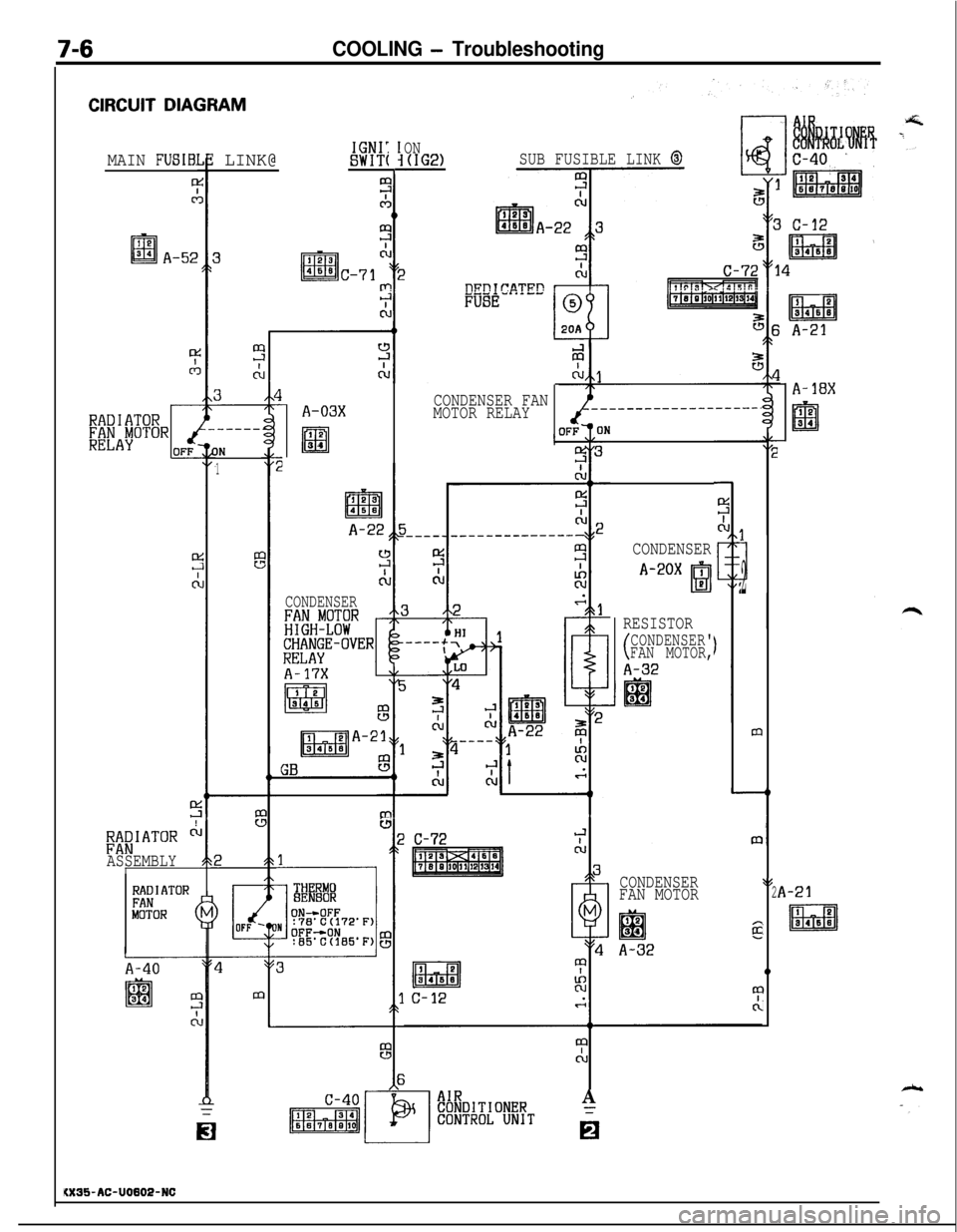
CIRCUIT DIAGRAM
ON(IG2)SUB FUSIBLE LINK @IGNI:SWIT(: LINK@MAIN FUSIB:
0
.-----
IN
1
A-18X
1CONDENSER
A-20X ,
I!31P2
RESISTOR
(CONDENSER'
FAN MOTOR,
A-32
m
A-21
IQ
Ed3B4SB
CONDENSER$l
FAN MOTOR2
12
lal34I
A-32
0
I
I
CONDENSER FAN
MOTOR RELAYA-03X
I 2lm34
A-22
CONDENSER
t----lTH RMOBE 80R
;;aIATOR ci
ASSEMBLY'
C-72
RADIATORFANMOTOR (
A-40
II
i0
A
6
KX35-AC-U0802-NC
Page 255 of 1216
COOLING - Troubleshooting7A7
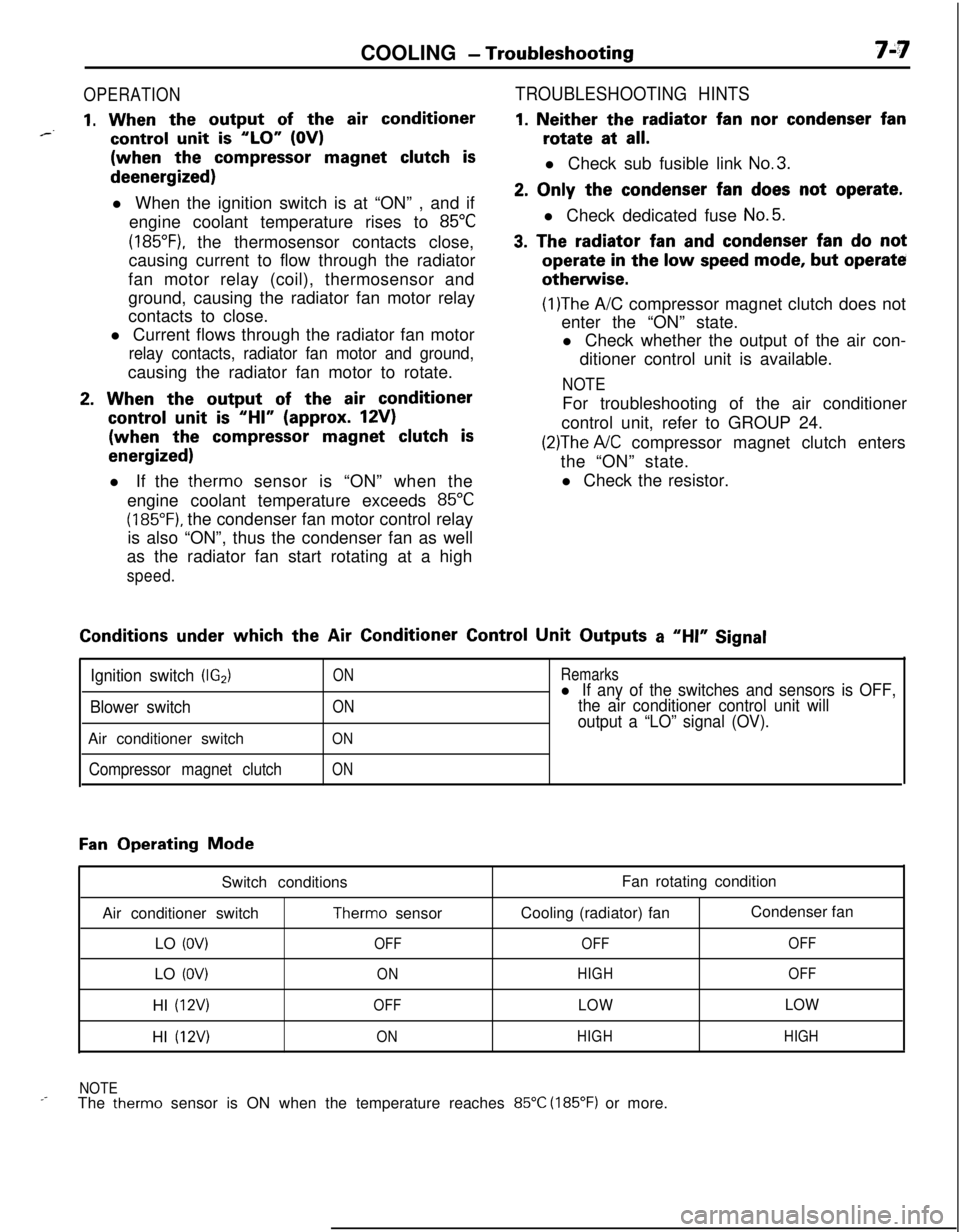
OPERATION
1. When the output of the air conditioner*--control unit is “LO” (OV)(when the
compressor magnet clutch isdeenergized)
l When the ignition switch is at “ON” , and if
engine coolant temperature rises to
85°C
(185”F), the thermosensor contacts close,
causing current to flow through the radiator
fan motor relay (coil), thermosensor and
ground, causing the radiator fan motor relay
contacts to close.
l Current flows through the radiator fan motor
relay contacts, radiator fan motor and ground,causing the radiator fan motor to rotate.
2. When the output of the air conditioner
control unit is “HI” (approx. 12V)(when the
compressor magnet clutch is
energized)l If the therm0 sensor is “ON” when the
engine coolant temperature exceeds
85°C
(185°F). the condenser fan motor control relay
is also “ON”, thus the condenser fan as well
as the radiator fan start rotating at a high
speed.
TROUBLESHOOTING HINTS
1. Neither the radiator fan nor condenser fanrotate at
all.l Check sub fusible link
No.3.
2. Only the condenser fan does not operate.l Check dedicated fuse
No.5.
3. The radiator fan and condenser fan do notoperate
in the low speed mode, but operateotherwise.
(1)The A/C compressor magnet clutch does not
enter the “ON” state.
l Check whether the output of the air con-
ditioner control unit is available.
NOTEFor troubleshooting of the air conditioner
control unit, refer to GROUP 24.
(2)The A/C compressor magnet clutch enters
the “ON” state.
l Check the resistor.Conditions
under which the Air Conditioner Control Unit Outputs a “HI” Signal
Ignition switch (IG2)
Blower switchAir conditioner switch
Compressor magnet clutch
ON
ON
ON
ON
Remarksl If any of the switches and sensors is OFF,
the air conditioner control unit will
output a “LO” signal (OV).
Fan Operating Mode
Switch conditions
Air conditioner switch
Therm0 sensor
LO
(OV)OFFLO
(OV)ONHI
(12V)OFFHI
(12V)ONFan rotating condition
Cooling (radiator) fanCondenser fan
OFFOFF
HIGHOFF
LOWLOW
HIGHHIGH
NOTE
_-The therm0 sensor is ON when the temperature reaches 85°C (185°F) or more.
Page 256 of 1216
7-8COOLING - Service Adjustment Procedures
04DooE
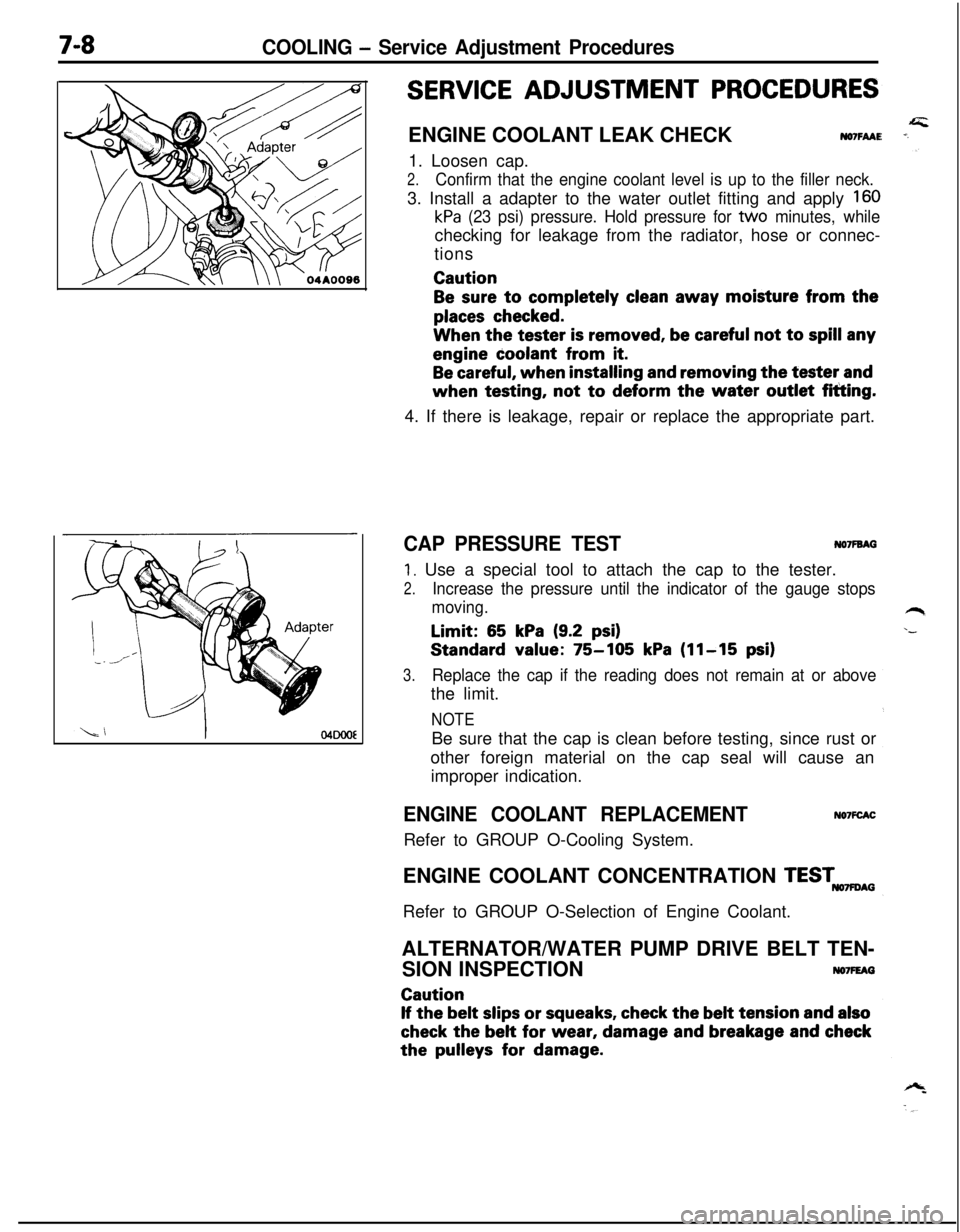
SERVICE ADJUSTMENT PROCEDURESENGINE COOLANT LEAK CHECK
NO7FAAE1. Loosen cap.
2.Confirm that the engine coolant level is up to the filler neck.3. Install a adapter to the water outlet fitting and apply
160
kPa (23 psi) pressure. Hold pressure for tvvo minutes, whilechecking for leakage from the radiator, hose or connec-
tionsCaution
Be sure to completely clean away moisture from the
places checked.When the tester
is removed, be careful not to spill anyengine coolant from
it.
Be careful, when installing and removing the tester andwhen testing, not
to deform the water outlet fitting.
4. If there is leakage, repair or replace the appropriate part.
CAP PRESSURE TESTNO’IFBAG
1. Use a special tool to attach the cap to the tester.
2.Increase the pressure until the indicator of the gauge stops
moving.Limit:
65 kPa (9.2 psi)Standard value:
75-105 kPa (11-15 psi)
3.Replace the cap if the reading does not remain at or abovethe limit.
NOTEBe sure that the cap is clean before testing, since rust or
other foreign material on the cap seal will cause an
improper indication.
ENGINE COOLANT REPLACEMENTRefer to GROUP O-Cooling System.NO’IFCACENGINE COOLANT CONCENTRATION
TESTmAGRefer to GROUP O-Selection of Engine Coolant.
ALTERNATOR/WATER PUMP DRIVE BELT TEN-
SION INSPECTION
NO7FEAGCaution
If the belt slips or squeaks, check the belt tension and also
check the belt for wear, damage and breakage and checkthe
pulleys for damage.
Page 260 of 1216
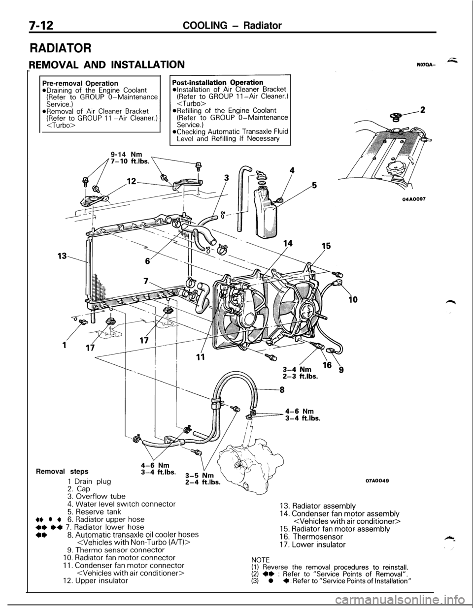
7-12COOLING - Radiator
RADIATORPre-removal Operation
@Draining of the Engine Coolant(Refer to GROUP O-Maintenance(Refer to GROUP II-Air Cleaner.)
Service.)
I I
9-14 Nm
_
4-6 Nm3-4 ft.lbs.Removal steps
1 Drain plug2. Cap3. Overflow tube.
4-9 Nm3-4 ft.lbs.
4. Water level switch connector
5. Reserve tank~~ l +6. Radiator upper hose
+e e+ 7. Radiator lower hose
*I)8. Automatic transaxle oil cooler hoses
11. Condenser fan motor connector
04AOOS7
07A0049
13. Radiator assembly14. Condenser fan motor assembly
16. Thermosensor
17. Lower insulator
NOTE(1) Reverse the removal procedures to reinstall.(2) +e : Refer to “Service Points of Removal”.(3) l + : Refer to “Service Points of Installation”
Page 261 of 1216

COOLING- Radiator7-13Mating
marks
04A0020
SERVICE POINTS OF REMOVALN07QBAH
6. REMOVAL OF RADIATOR UPPER HOSE/7. RADIATOR
LOWER HOSEAfter making mating marks on the radiator hose and the
hose clamp, disconnect the radiator hose.
8. DISCONNECTION OF AUTOMATIC TRANSAXLE OIL
COOLER HOSESUse a plug or otherwise cover the hose and nipple part of
the radiator so that dust, dirt, foreign materials, etc. do not
enter after the hose has been disconnected from the
radiator.
INSPECTIONNo7OcAMl Check for foreign material between radiator fins.
l Check the radiator fins for bent, or damage.
l Check the radiator for corrosion, damage rust or scale.
lCheck the radiator hoses for cracks, damage or deteriora-
tion.l Check the reserve tank for damage.
lCheck the automatic transaxle oil cooler hoses for cracking,damage or deterioration.
RADIATOR FAN MOTOR INSPECTION(1) Check to be sure that the radiator fan rotates when batten/
voltage is applied between terminals (as shown in the
figure).
(2) Check to see that abnormal noises are not produced, whilemotor is turning.
THERM0 SENSOR INSPECTIONCheck for continuity with the therm0 sensor in hot water.
NOTEImmerse therm0 sensor in hot water up to mounting thread to
check for continuity.