clock MITSUBISHI ECLIPSE 1991 Service Manual
[x] Cancel search | Manufacturer: MITSUBISHI, Model Year: 1991, Model line: ECLIPSE, Model: MITSUBISHI ECLIPSE 1991Pages: 1216, PDF Size: 67.42 MB
Page 110 of 1216
3-8REAR AXLE - Service Adjustment Procedures
09D031
llA0065SERVICE ADJUSTMENT PROCEDURES
REAR AXLE TOTAL BACKLASH CHECK
N03FAAF
If the vehicle vibrates and produces a booming sound due to animbalance of the driving system, measure the rear axle total
backlash by the following procedures to see if the differential
carrier assembly required removal.
(1) Place the gearshift lever in the neutral position, apply the
parking brake and jack up the vehicle.
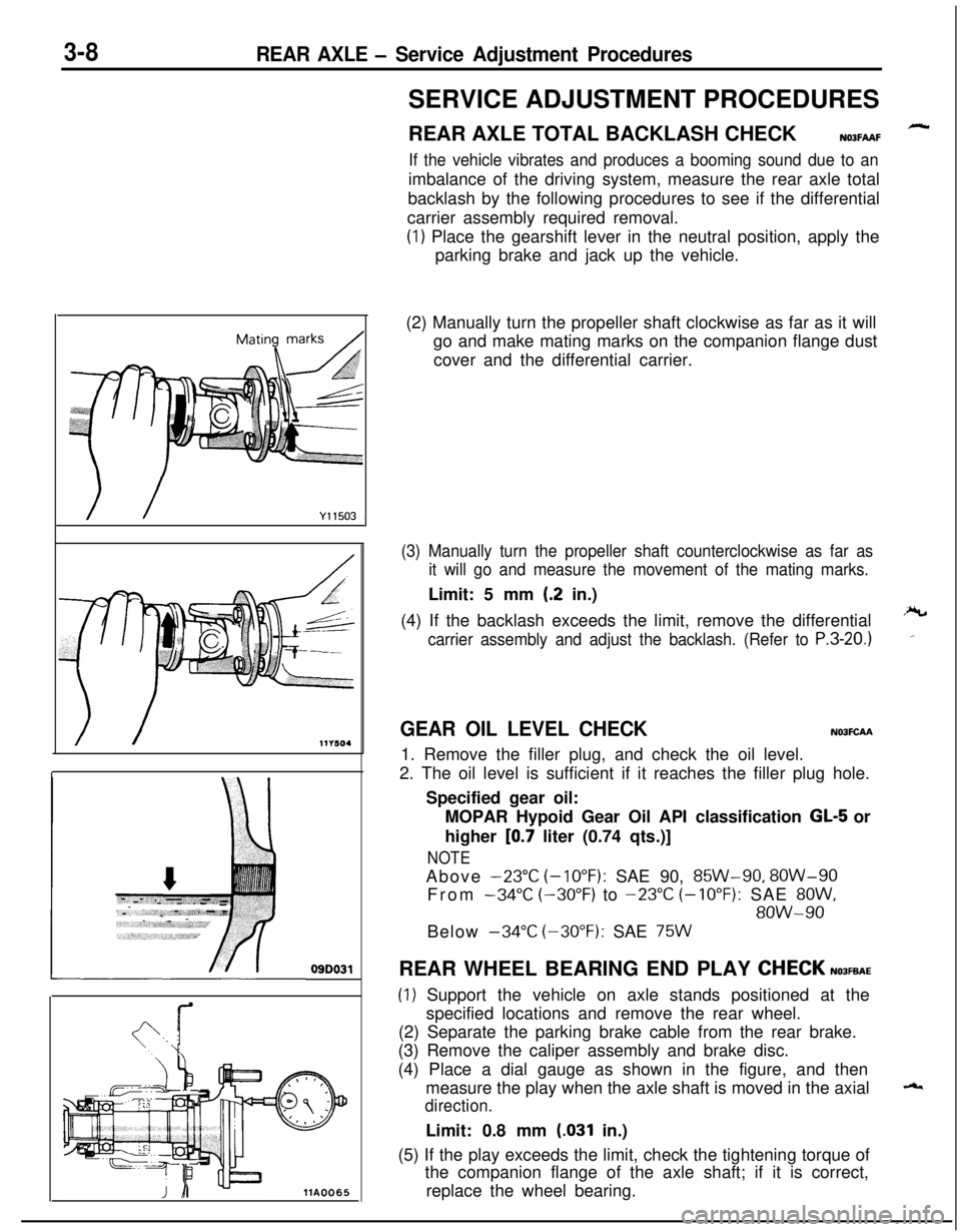
(2) Manually turn the propeller shaft clockwise as far as it will
go and make mating marks on the companion flange dust
cover and the differential carrier.
(3) Manually turn the propeller shaft counterclockwise as far as
it will go and measure the movement of the mating marks.Limit: 5 mm
(.2 in.)
(4) If the backlash exceeds the limit, remove the differential
carrier assembly and adjust the backlash. (Refer to P.3-20.)
GEAR OIL LEVEL CHECKN03FCAA1. Remove the filler plug, and check the oil level.
2. The oil level is sufficient if it reaches the filler plug hole.
Specified gear oil:
MOPAR Hypoid Gear Oil API classification
GL-5 or
higher
[0.7 liter (0.74 qts.)]
NOTEAbove
-23°C (-10°F): SAE 90, 85W-90, 8OW-90
From
-34°C (-30°F) to -23°C (-10°F): SAE 8OW,
8OW-90Below
-34°C (-30°F): SAE 75WREAR WHEEL BEARING END PLAY
CHECKN03FEAE
(1) Support the vehicle on axle stands positioned at the
specified locations and remove the rear wheel.
(2) Separate the parking brake cable from the rear brake.
(3) Remove the caliper assembly and brake disc.
(4) Place a dial gauge as shown in the figure, and then
measure the play when the axle shaft is moved in the axial
direction.Limit: 0.8 mm
(.031 in.)
(5) If the play exceeds the limit, check the tightening torque of
the companion flange of the axle shaft; if it is correct,
replace the wheel bearing.
Page 258 of 1216
COOLING - Service Adjustment Procedures100N
(22 Ibs.)
DeflecAlternator
ypulley
:tion
6COOOO9
Spindle ,
HookOlLO149
IncorrectCorrectIncorrect
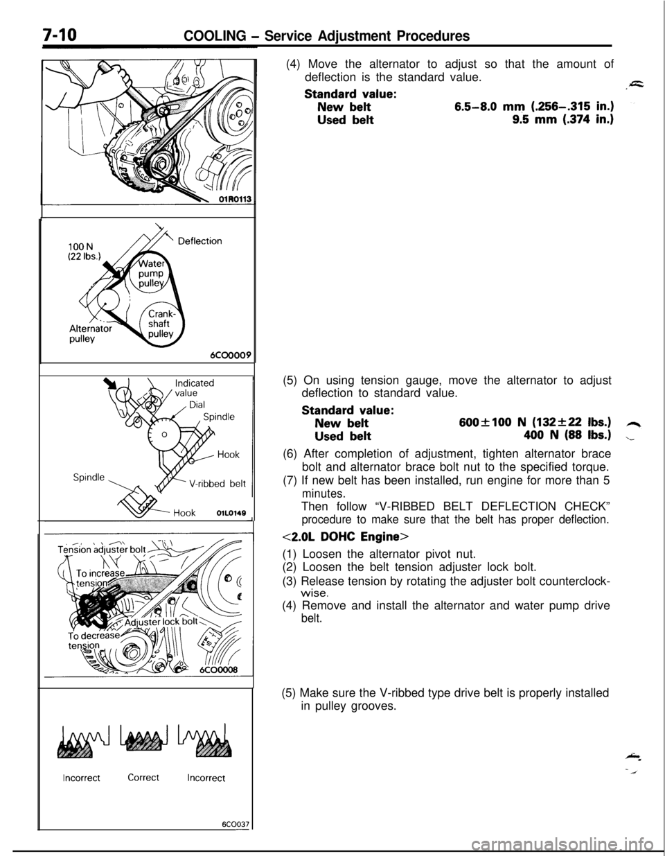
6COO37-(4) Move the alternator to adjust so that the amount of
deflection is the standard value.Standard
value:
New belt6.5-8.0 mm (.256-.315 in.)
Used belt9.5 mm (.374 in.)(5) On using tension gauge, move the alternator to adjust
deflection to standard value.Standard
value:
New belt600flOO N (132+22 Ibs.)
Used belt400 N (88 Ibs.)(6) After completion of adjustment, tighten alternator brace
bolt and alternator brace bolt nut to the specified torque.
(7) If new belt has been installed, run engine for more than 5
minutes.Then follow “V-RIBBED BELT DEFLECTION CHECK”
procedure to make sure that the belt has proper deflection.
<2.0L DOHC Engine>
(1) Loosen the alternator pivot nut.
(2) Loosen the belt tension adjuster lock bolt.
(3) Release tension by rotating the adjuster bolt counterclock-
wise.(4) Remove and install the alternator and water pump drive
belt.(5) Make sure the V-ribbed type drive belt is properly installed
in pulley grooves.
Page 259 of 1216
COOLING - Service Adjustment Procedures7-m
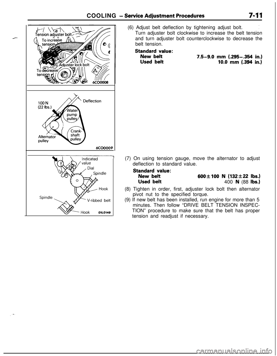
1(6) Adjust belt deflection by tightening adjust bolt.
:Turn adjuster bolt clockwise to increase the belt tension
and turn adjuster bolt counterclockwise to decrease the
belt tension.
Standard value:
New belt7.5-9.0 mm (.295-.354 in.)
Used belt10.0 mm (.394 in.)(7) On using tension gauge, move the alternator to adjust
deflection to standard value.
Standard value:
New belt600+100 N (132f22 Ibs.)
Used belt
400 N (88 Ibs.)(8) Tighten in order, first, adjuster lock bolt then alternator
pivot nut to the specified torque.
(9) If new belt has been installed, run engine for more than 5
minutes. Then follow “DRIVE BELT TENSION INSPEC-
TION” procedure to make sure that the belt has proper
tension and readjust if necessary.
Page 310 of 1216
9-26ENGINE <1.8L Engine> -Service Adjustment Procedures
TIMING BELT TENSION ADJUSTMENTNOSFGBCThere are two access holes provided in the timing belt front
lower cover. The two access holes can be used to readjust thetension of the timing belt, by following the procedures
described below, without the necessity of removing the timing
belt front lower cover. Note, however, that timing belt “B”,
which drives the right silent shaft, cannot be adjusted unless
the cover is removed.
(1) Turn the steering wheel all the way to the left.
(2) Remove the left side undercover panel.
NOTEThis work is done so that the crankshaft can be turned.
(3) Place a piece of wood against the engine oil pan and jack
(4)
:tmove the engine mounting bracket.
(5) Remove the timging belt front upper cover.
(6) Remove the four spark plugs.
(7) Turn the crankshaft clockwise and check the timing belt
condition.
OlAOOBlTiming mark
(on upper under cover)
Timing mark
(on camshaft sprocket)
OlR0153cover
‘I!i
OlA0082
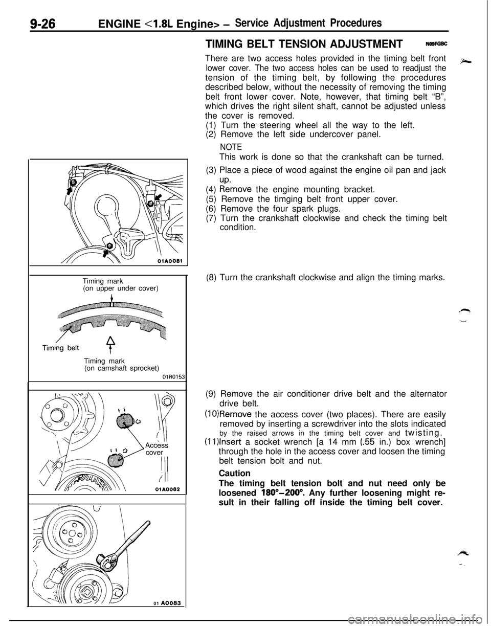
01 A0083(8) Turn the crankshaft clockwise and align the timing marks.
(9) Remove the air conditioner drive belt and the alternator
drive belt.
(10)Remove the access cover (two places). There are easily
removed by inserting a screwdriver into the slots indicated
by the raised arrows in the timing belt cover and twisting.
(1l)lnser-t a socket wrench [a 14 mm (.55 in.) box wrench]
through the hole in the access cover and loosen the timing
belt tension bolt and nut.
Caution
The timing belt tension bolt and nut need only be
loosened
180”-200”. Any further loosening might re-
sult in their falling off inside the timing belt cover.
Page 311 of 1216
ENGINE <1.8L Engine> -Service Adjustment Procedures9-27
I.
Timing mark(on upper under cover)Timing belt
Timing mark
A(on camshaft
sprocket)OlR0154
3EN076
3EN07;-
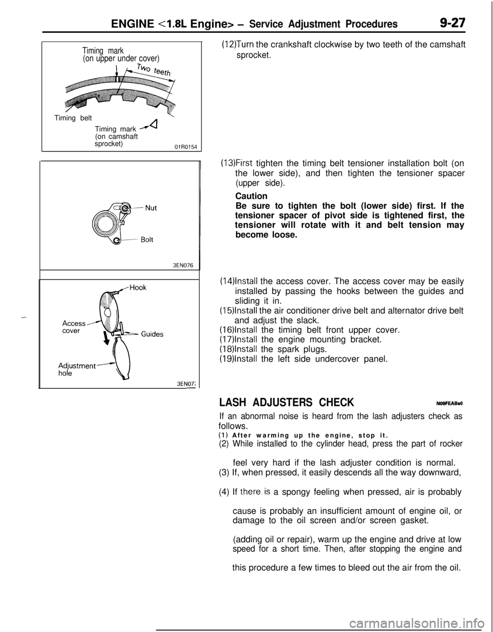
(12)Turn the crankshaft clockwise by two teeth of the camshaft
sprocket.
(13)First tighten the timing belt tensioner installation bolt (on
the lower side), and then tighten the tensioner spacer
(upper side).Caution
Be sure to tighten the bolt (lower side) first. If the
tensioner spacer of pivot side is tightened first, the
tensioner will rotate with it and belt tension may
become loose.
(14)lnstall the access cover. The access cover may be easily
installed by passing the hooks between the guides and
sliding it in.
(15)lnstall the air conditioner drive belt and alternator drive belt
and adjust the slack.
(16)lnstalI the timing belt front upper cover.
(17)lnstall the engine mounting bracket.
(18)lnstalI the spark plugs.
(19)lnstall the left side undercover panel.
LASH ADJUSTERS CHECKNO9FEABaO
If an abnormal noise is heard from the lash adjusters check asfollows.
(I) After warming up the engine, stop it.
(2) While installed to the cylinder head, press the part of rockerfeel very hard if the lash adjuster condition is normal.
(3) If, when pressed, it easily descends all the way downward,
(4) If there.is a spongy feeling when pressed, air is probably
cause is probably an insufficient amount of engine oil, or
damage to the oil screen and/or screen gasket.
(adding oil or repair), warm up the engine and drive at low
speed for a short time. Then, after stopping the engine andthis procedure a few times to bleed out the air from the oil.
Page 322 of 1216
9-38ENGINE <1.8L Engine> - Cylinder Head Gasket
04UOO27Timing mark
\Timing mark
OlR0153
SERVICE POINTS OF REMOVALNWJSAO7. REMOVAL OF RADIATOR UPPER HOSE
,zMake mating marks on the radiator hose and hose clamp,
b-and then disconnect the radiator hose.
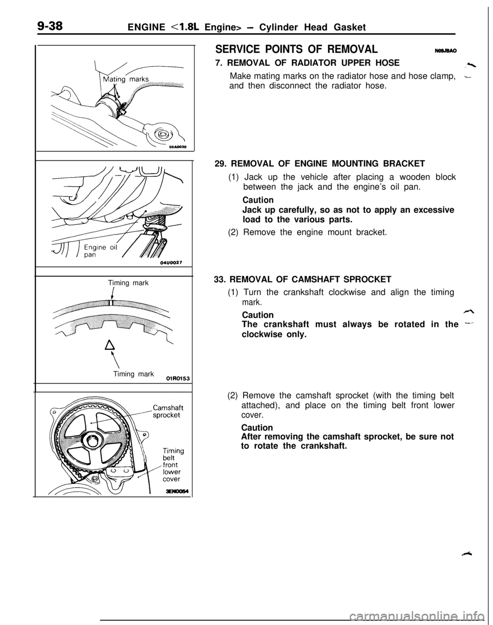
29. REMOVAL OF ENGINE MOUNTING BRACKET
(1) Jack up the vehicle after placing a wooden block
between the jack and the engine’s oil pan.
CautionJack up carefully, so as not to apply an excessive
load to the various parts.
(2) Remove the engine mount bracket.
33. REMOVAL OF CAMSHAFT SPROCKET
(1) Turn the crankshaft clockwise and align the timing
mark.Caution
rzThe crankshaft must always be rotated in the
-’clockwise only.
(2) Remove the camshaft sprocket (with the timing belt
attached), and place on the timing belt front lower
cover.Caution
After removing the camshaft sprocket, be sure not
to rotate the crankshaft.
R
Page 326 of 1216
g-42ENGINE <1.8L Engine> - Timing Belt
r-04UOO27
,Timing mark
Timing‘mark
lEN0017
c
li
OlA0550SERVICE POINTS OF REMOVAL
NO9KBBCa2. REMOVAL OF ENGINE MOUNT BRACKET
a(1) Jack up the vehicle after placing a wooden block
:.between the jack and the engine’s oil pan.
CautionJack up carefully so as not to apply an excessive
load to the various parts.
(2) Remove the engine mount bracket.
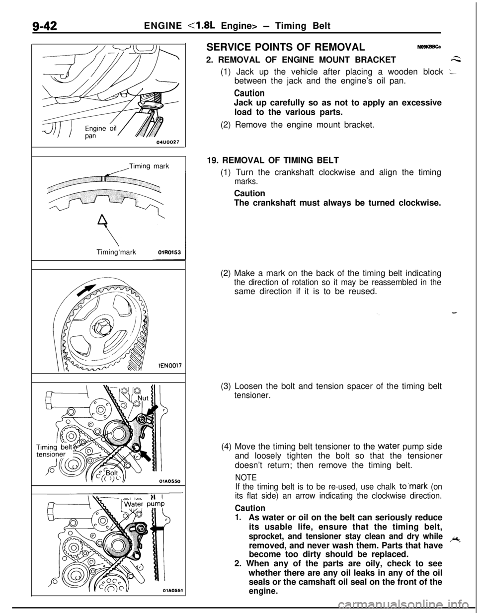
19. REMOVAL OF TIMING BELT
(1) Turn the crankshaft clockwise and align the timing
marks.Caution
The crankshaft must always be turned clockwise.
(2) Make a mark on the back of the timing belt indicating
the direction of rotation so it may be reassembled in thesame direction if it is to be reused.
(3) Loosen the bolt and tension spacer of the timing belt
tensioner.(4) Move the timing belt tensioner to the water pump side
and loosely tighten the bolt so that the tensioner
doesn’t return; then remove the timing belt.
NOTE
If the timing belt is to be re-used, use chalk to’mark (on
its flat side) an arrow indicating the clockwise direction.
Caution
1.As water or oil on the belt can seriously reduce
its usable life, ensure that the timing belt,
sprocket, and tensioner stay clean and dry whileremoved, and never wash them. Parts that haveic
*become too dirty should be replaced.
2. When any of the parts are oily, check to see
whether there are any oil leaks in any of the oil
seals or the camshaft oil seal on the front of the
engine.
Page 330 of 1216
9-46ENGINE <1.8L Engine> - Timing Belt
Timing mark
Q1hQS4.9
3EN005
OlA0549
c
::
OlAO550-(3) Move tensioner fully toward water pump and tempor-
arily secure tensioner.
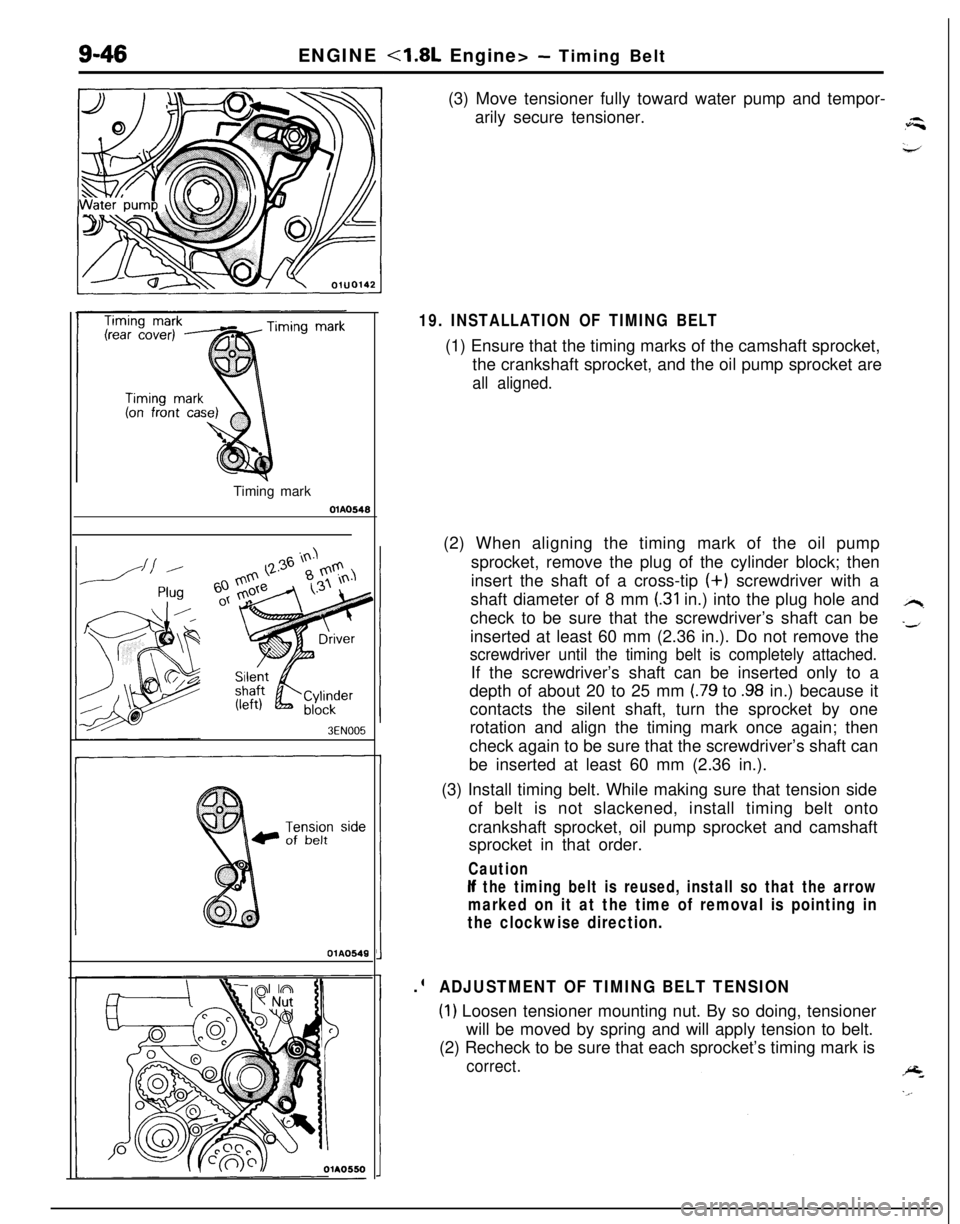
19. INSTALLATION OF TIMING BELT(1) Ensure that the timing marks of the camshaft sprocket,
the crankshaft sprocket, and the oil pump sprocket are
all aligned.(2) When aligning the timing mark of the oil pump
sprocket, remove the plug of the cylinder block; then
insert the shaft of a cross-tip (+) screwdriver with a
shaft diameter of 8 mm
(.31 in.) into the plug hole and
check to be sure that the screwdriver’s shaft can be
inserted at least 60 mm (2.36 in.). Do not remove the
screwdriver until the timing belt is completely attached.If the screwdriver’s shaft can be inserted only to a
depth of about 20 to 25 mm
(.79 to .98 in.) because it
contacts the silent shaft, turn the sprocket by one
rotation and align the timing mark once again; then
check again to be sure that the screwdriver’s shaft can
be inserted at least 60 mm (2.36 in.).
(3) Install timing belt. While making sure that tension side
of belt is not slackened, install timing belt onto
crankshaft sprocket, oil pump sprocket and camshaft
sprocket in that order.
Caution
If the timing belt is reused, install so that the arrow
marked on it at the time of removal is pointing in
the clockwise direction..
ADJUSTMENT OF TIMING BELT TENSION
(1) Loosen tensioner mounting nut. By so doing, tensioner
will be moved by spring and will apply tension to belt.
(2) Recheck to be sure that each sprocket’s timing mark is
correct.
Page 331 of 1216
ENGINE <1.8L Engine> - Timing Belt9-47
Timing mark
Nut
;olt diameter x lengthim (in.)
6x50(.23 x 1.97)
6
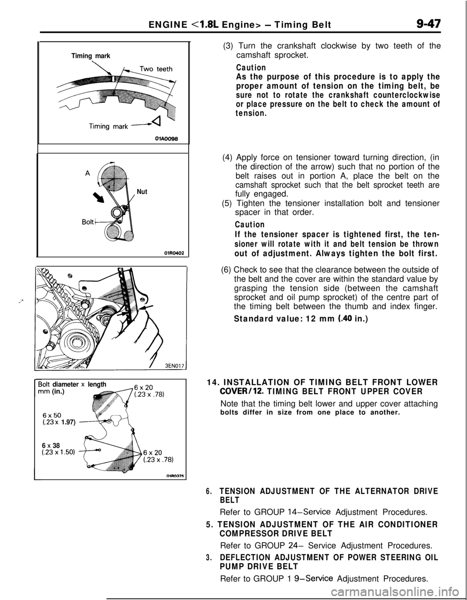
x 38(.23 x 1.50)(3) Turn the crankshaft clockwise by two teeth of the
camshaft sprocket.
Caution
As the purpose of this procedure is to apply the
proper amount of tension on the timing belt, be
sure not to rotate the crankshaft counterclockwise
or place pressure on the belt to check the amount of
tension.(4) Apply force on tensioner toward turning direction, (in
the direction of the arrow) such that no portion of the
belt raises out in portion A, place the belt on the
camshaft sprocket such that the belt sprocket teeth arefully engaged.
(5) Tighten the tensioner installation bolt and tensioner
spacer in that order.
Caution
If the tensioner spacer is tightened first, the ten-
sioner will rotate with it and belt tension be thrown
out of adjustment. Always tighten the bolt first.(6) Check to see that the clearance between the outside of
the belt and the cover are within the standard value by
grasping the tension side (between the camshaft
sprocket and oil pump sprocket) of the centre part of
the timing belt between the thumb and index finger.
Standard value: 12 mm (.40 in.)
14. INSTALLATION OF TIMING BELT FRONT LOWER
COVER/12. TIMING BELT FRONT UPPER COVERNote that the timing belt lower and upper cover attaching
bolts differ in size from one place to another.
6.TENSION ADJUSTMENT OF THE ALTERNATOR DRIVE
BELTRefer to GROUP
14-Service Adjustment Procedures.
5. TENSION ADJUSTMENT OF THE AIR CONDITIONER
COMPRESSOR DRIVE BELTRefer to GROUP
24- Service Adjustment Procedures.
3.DEFLECTION ADJUSTMENT OF POWER STEERING OIL
PUMP DRIVE BELTRefer to GROUP 1
g-Service Adjustment Procedures.
Page 381 of 1216
--ENGINE
<2.0L DOHC Engine> - Timing Belt9-97
ExhaustIntake cam-
CrankshaftsproketsprockekOlhw51
1r
SERVICE POINTS OF REMOVAL-a3. REMOVAL OF ENGINE MOUNT BRACKET
(1) With a wooden block placed against the oil pan part of
the engine, jack up the vehicle.
CautionJack up gently, so as not to apply a load to the
various parts.
(2) Remove the engine mount bracket,
5. REMOVAL OF DRIVE BELT (ALTERNATOR)
Before removing the drive belt, loosen the water pump
pulley mounting bolts.
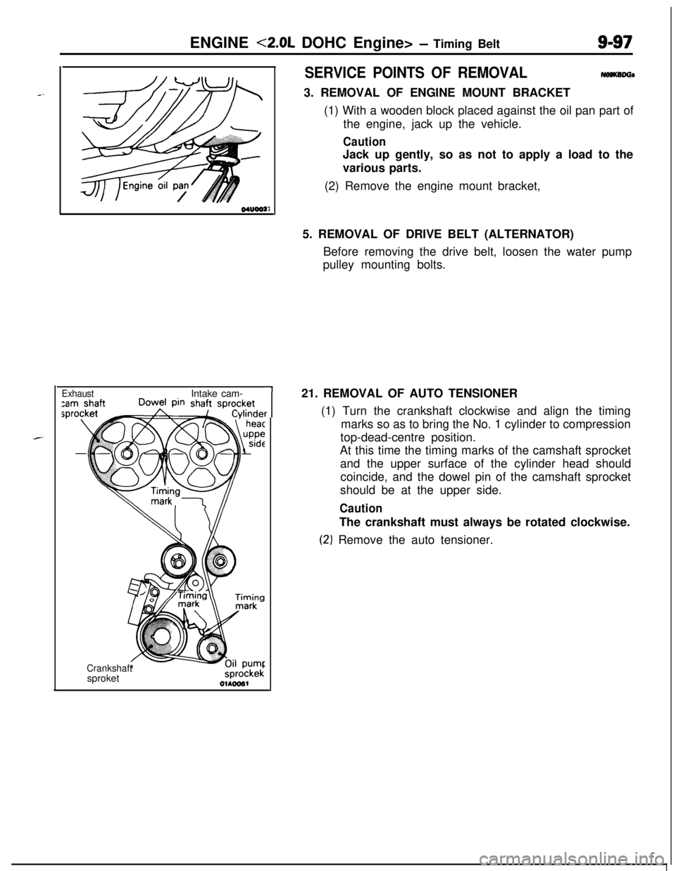
21. REMOVAL OF AUTO TENSIONER
(1) Turn the crankshaft clockwise and align the timing
marks so as to bring the No. 1 cylinder to compression
top-dead-centre position.
At this time the timing marks of the camshaft sprocket
and the upper surface of the cylinder head should
coincide, and the dowel pin of the camshaft sprocket
should be at the upper side.
CautionThe crankshaft must always be rotated clockwise.
(2‘) Remove the auto tensioner.