ESP MITSUBISHI ECLIPSE 1993 Workshop Manual
[x] Cancel search | Manufacturer: MITSUBISHI, Model Year: 1993, Model line: ECLIPSE, Model: MITSUBISHI ECLIPSE 1993Pages: 57, PDF Size: 4.18 MB
Page 4 of 57

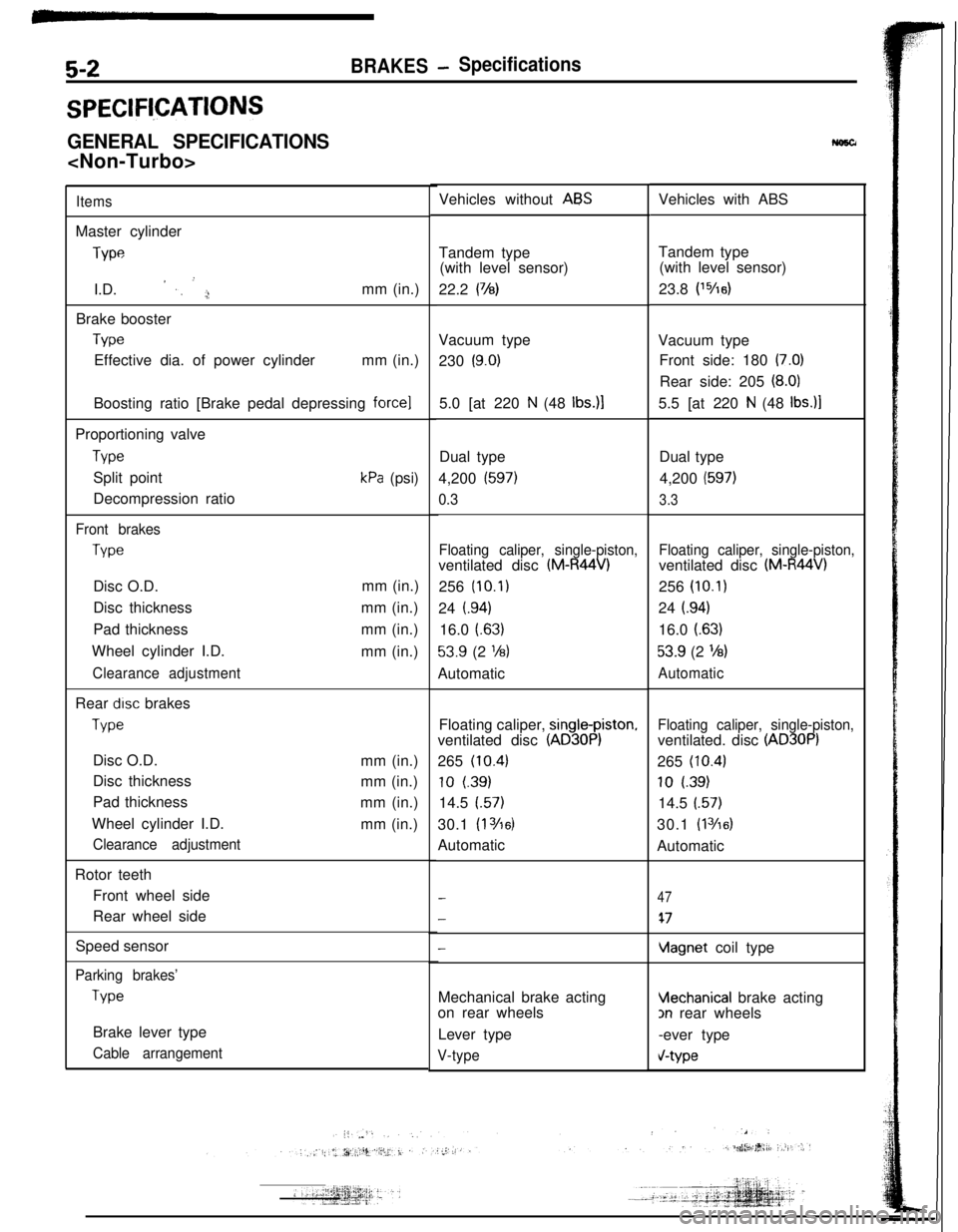
5-2BRAKES- Specifications
SPECIFl,CATIONS
GENERAL SPECIFICATIONS
ItemsMaster cylinder
J-wI.D.
’ ,, ’ ,;!mm (in.)
Brake booster
TvwEffective dia. of power cylindermm (in.)
Boosting ratio [Brake pedal depressing
force]5.0 [at 220 N (48 Ibs.)lProportioning valve
TypeSplit point
Decompression ratio
kPa (psi)
Front brakes
TypeDisc O.D.
Disc thickness
Pad thickness
Wheel cylinder I.D.
Clearance adjustmentmm (in.)
mm (in.)
mm (in.)
mm (in.)
Rear
drsc brakes
TypeDisc O.D.
Disc thickness
Pad thickness
Wheel cylinder I.D.
Clearance adjustmentmm (in.)
mm (in.)
mm (in.)
mm (in.)
Rotor teeth
Front wheel side
Rear wheel side
Speed sensor
-
Parking brakes’
TvwBrake lever type
Cable arrangementVehicles without
ABSVehicles with ABS
Tandem type
(with level sensor)
22.2
(78)Tandem type
(with level sensor)
23.8 P5/1dVacuum type
230
(9.0)Vacuum type
Front side: 180 (7.0)Rear side: 205
(8.0)5.5 [at 220
N (48 Ibs.)lDual type
4,200
(597)
0.3Dual type
4,200
(597)
3.3
Floating caliper, single-piston,ventilated disc
(M-R44V)256
(10.1)24
i.94)16.0
(.63)
53.9 (2 l/8)Automatic
Floating caliper, single-piston,ventilated disc
(M-R44V)256
(10.1)24
i.94)16.0
(.63)
53.9 (2 %)
AutomaticFloating caliper,
single-piston,ventilated disc
(AD30P)265
(10.43
10 (39)
14.5
(.57)30.1
(1 Yl6)Automatic
Floating caliper, single-piston,ventilated. disc
(AD30P)265
(10.4)
10 l.39)14.5
(.57)30.1
(1 3/6)Automatic
-
-
47
47
vlagnet coil type
Mechanical brake acting
Vlechanical brake acting
on rear wheels
3n rear wheels
Lever type
-ever type
V-typeV-type
Page 8 of 57

5-50BRAKES - Service Adjustment Proi?edur&
Brakebooster
sideSpring
’
/
Valve
Pressure
gaugePressure
PropGtioning valve14LO181input pressure
14uoo55
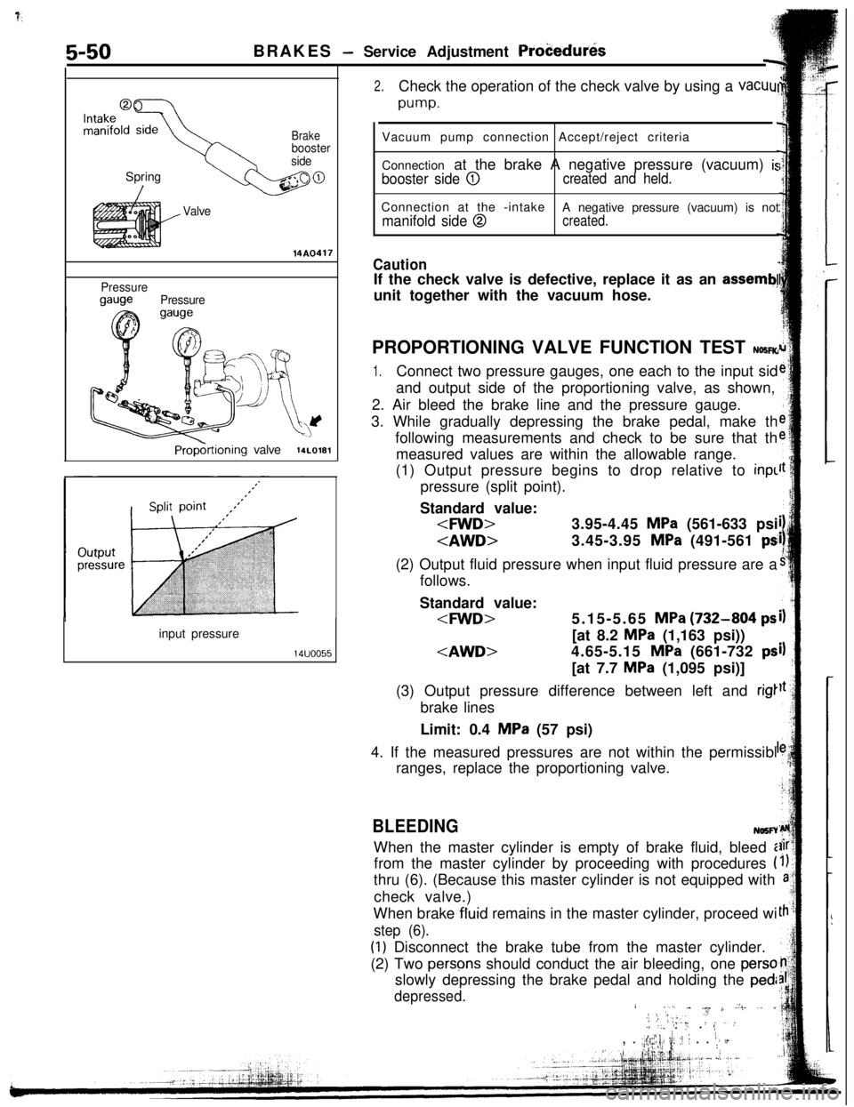
2.Check the operation of the check valve by using a vacuul
pump.Vacuum pump connection Accept/reject criteria
Connection at the brake A negative pressure (vacuum)
is
booster side @created and held.Connection at the -intake
manifold side @A negative pressure (vacuum) is notcreated.
CautionIf the check valve is defective, replace it as an
assemb!unit together with the vacuum hose.
PROPORTIONING VALVE FUNCTION TEST
NO!iR(r
1.Connect two pressure gauges, one each to the input sid
and output side of the proportioning valve, as shown,
2. Air bleed the brake line and the pressure gauge.
3. While gradually depressing the brake pedal, make th
following measurements and check to be sure that th
measured values are within the allowable range.
(1) Output pressure begins to drop relative to inpl
pressure (split point).
Standard value:
follows.
Standard value:
MPa (1,163 psi))
MPa (1,095 psi)]
(3) Output pressure difference between left and
rig1brake lines
Limit: 0.4
MPa (57 psi)
4. If the measured pressures are not within the permissibl
ranges, replace the proportioning valve.
BLEEDINGNo5FYWhen the master cylinder is empty of brake fluid, bleed i
from the master cylinder by proceeding with procedures
(thru (6). (Because this master cylinder is not equipped with
check valve.)
When brake fluid remains in the master cylinder, proceed wi
step (6).
(1) Disconnect the brake tube from the master cylinder.
(2) Two
persqs should conduct the air bleeding, one persoslowly depressing the brake pedal and holding the
ped:
depressed.i .I..[ j,‘I- .~ j, Z’:. ~. jl2;:‘,.Y .‘.:./ ‘:” ‘: ,, . 8,, .
.;$y; ii; :: 1 . . i;, d
Page 30 of 57

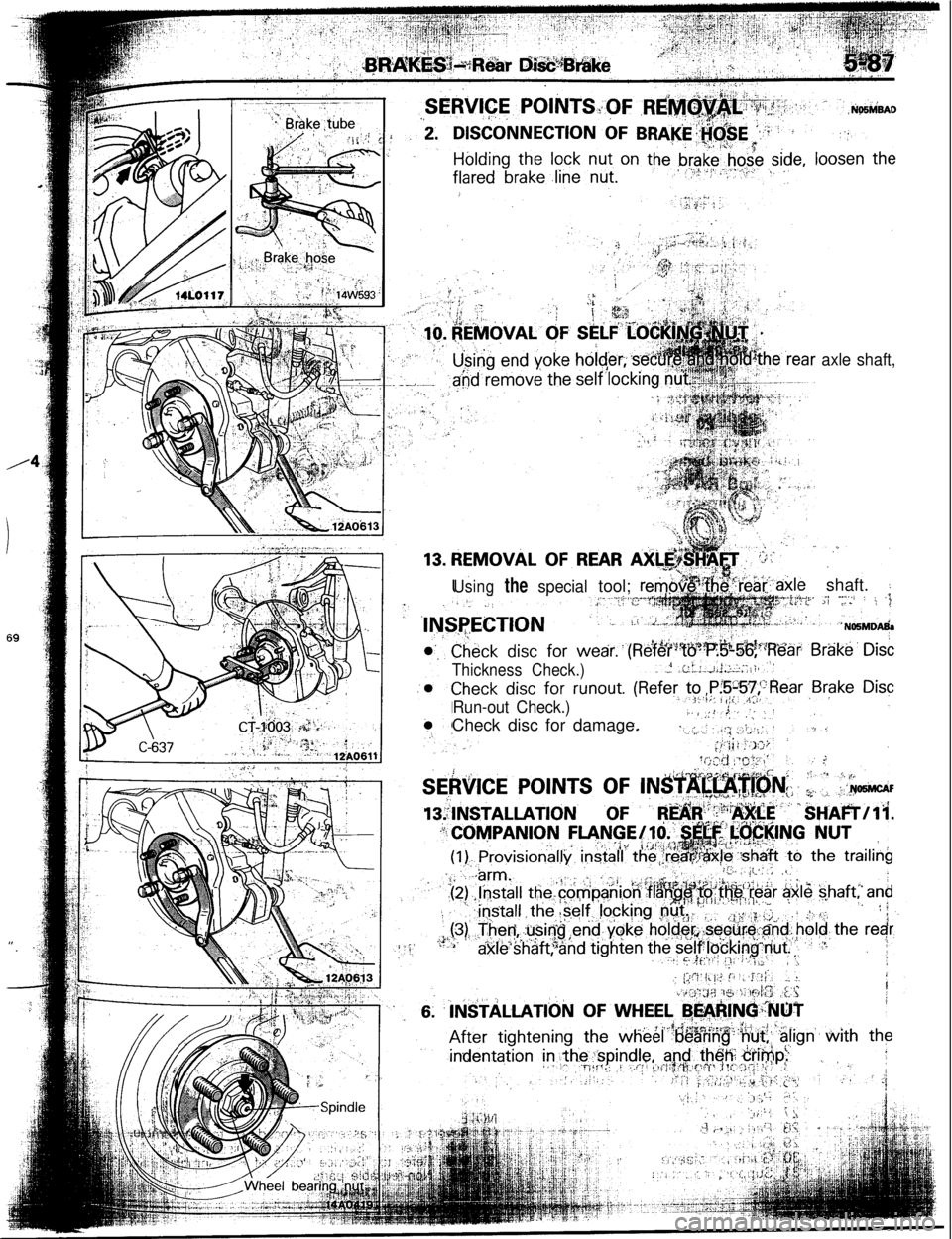
axle shaft,
Usingthespecialtool; r:&.le shaft. :.;; -..s../ : i 3<.- Ef
Thickness Check.)
Run-out Check.)Check disc for damage.
Page 31 of 57

~~~HEEL AND TIREN22GA..
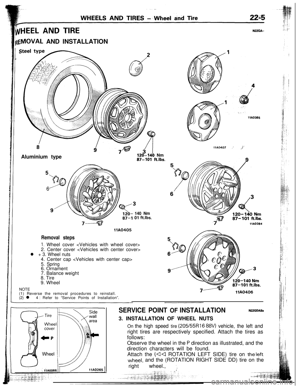
{EMOVAL AND INSTALLATION
Aluminium type
120-140 Nm87-101 ft.lbs.
6
140 Nm01 ft.lbs.
llA0405
Removal steps
I. Wheel cover
2. Center cover
l + 3. Wheel nuts4. Center cap
5. Spring6. Ornament
NOTE7. Balance weight
8. Tire
9. Wheel
(1) Reverse the removal procedures to reinstall.
(2) l 4
: Refer to “Service Points of Installation”.llA0366
llA0407,’ J’
7VA0364
llA0406
SERVICE POINT OF INSTALLATIONN22GDABs3. INSTALLATION OF WHEEL NUTS
On the high speed tire (205/55Rl6 88V) vehicle, the left andright tires are respectively specified. Attach the tires as
follows:
Observe the wheel in the
P direction as illustrated, and the
direction characters will be found.
Attach the
(44 ROTATION LEFT SIDE) tire on the leftwheel, and the (ROTATION RIGHT SIDE DD) tire on the
right wheel.,
1.