wheel MITSUBISHI ECLIPSE CROSS 2018 (in English) Owner's Guide
[x] Cancel search | Manufacturer: MITSUBISHI, Model Year: 2018, Model line: ECLIPSE CROSS, Model: MITSUBISHI ECLIPSE CROSS 2018Pages: 417, PDF Size: 74.06 MB
Page 127 of 417
Parking brake 5-48 Features and controls
5
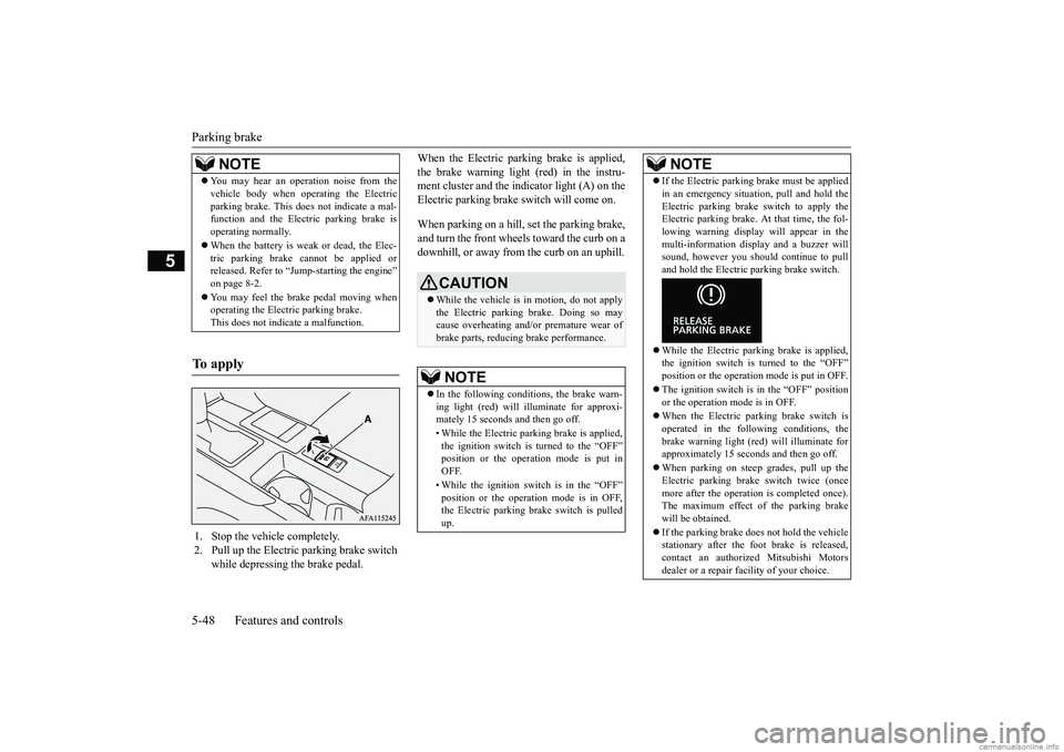
When the Electric parking brake is applied, the brake warning light (red) in the instru- ment cluster and the indicator light (A) on the Electric parking brake switch will come on. When parking on a hill, set the parking brake, and turn the front wheels toward the curb on a downhill, or away from the curb on an uphill.
NOTE
You may hear an operation noise from the vehicle body when operating the Electric parking brake. This does not indicate a mal- function and the Electric parking brake is operating normally. When the battery is weak or dead, the Elec- tric parking brake cannot be applied orreleased. Refer to “Jump-starting the engine” on page 8-2. You may feel the brake pedal moving when operating the Electric parking brake. This does not indicate a malfunction.
To apply
1. Stop the vehicle completely. 2. Pull up the Electric parking brake switch
while depressing the brake pedal.
CAUTION While the vehicle is in motion, do not apply the Electric parking brake. Doing so may cause overheating and/or premature wear of brake parts, reducing brake performance. NOTE
In the following conditions, the brake warn- ing light (red) will illuminate for approxi- mately 15 seconds and then go off. • While the Electric parking brake is applied, the ignition switch is turned to the “OFF”position or the operation mode is put in OFF. • While the ignition switch is in the “OFF” position or the operation mode is in OFF, the Electric parking brake switch is pulled up.
If the Electric parking brake must be applied in an emergency situation, pull and hold the Electric parking brake switch to apply the Electric parking brake. At that time, the fol- lowing warning display will appear in themulti-information display and a buzzer will sound, however you should continue to pull and hold the Electric parking brake switch. While the Electric parking brake is applied, the ignition switch is turned to the “OFF” position or the operation mode is put in OFF. The ignition switch is in the “OFF” position or the operation mode is in OFF. When the Electric parking brake switch is operated in the following conditions, thebrake warning light (red) will illuminate for approximately 15 seconds and then go off. When parking on steep grades, pull up the Electric parking brake switch twice (once more after the operation is completed once).The maximum effect of the parking brake will be obtained. If the parking brake does not hold the vehicle stationary after the foot brake is released,contact an authorized Mitsubishi Motors dealer or a repair facility of your choice.NOTE
BK0252700US.bo
ok 48 ページ 2017年10月4日 水曜日 午後4時54分
Page 129 of 417
Steering wheel height and reach adjustment 5-50 Features and controls
5
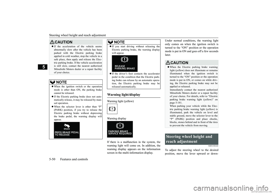
Warning light (yellow) Warning display If there is a malfunction in the system, the warning light will come on. In addition, thewarning display appears on the informationscreen in the multi-information display.
Under normal conditions, the warning light only comes on when the ignition switch is turned to the “ON” position or the operation mode is put in ON and goes off a few secondslater.
N00511501241
To adjust the steering wheel to the desiredposition, move the lever upward or down-
If the acceleration of the vehicle seems abnormally slow after the vehicle has been parked with the Electric parking brake applied in cold weather, stop the vehicle in a safe place, then apply and release the Elec-tric parking brake. If the vehicle acceleration is still slow, contact the nearest authorized Mitsubishi Motors dealer or a repair facilityof your choice.NOTE
When the ignition switch or the operation mode is other than ON, the parking brake cannot be released. If the Electric parking brake does not auto- matically release, it may be released by man-ual operation. When the selector lever is other than “P” (PARK) position, if you try to release the Electric parking brake without depressing the brake pedal, the warning display willappear.CAUTION
If you start driving without releasing the Electric parking brake, the warning display will appear. If the driver’s foot contacts the accelerator pedal in the condition that the Electric park-ing brake can release by an automatic opera- tion, the Electric parking brake may be released automatically.
Warning light/display
NOTE
CAUTION When the Electric parking brake warning light (yellow) does not illuminate or remains illuminated when the ignition switch isturned to the “ON” position or the operation mode is put in ON, or comes on while driv- ing, the Electric parking brake may not beapplied or released. Immediately contact the nearest authorized Mitsubishi Motors dealer or a repair facilityof your choice. For details, refer to “Electric parking brake warning light (yellow)” on page 5-181.When parking your vehicle while the Elec- tric parking brake warning light (yellow) is illuminated, park the vehicle on level andstable ground, move the selector lever to the “P” (PARK) position and place chocks, blocks, stones behind and in front of the tiresto prevent the vehicle from moving.
Steering wheel height and reach adjustment
BK0252700US.bo
ok 50 ページ 2017年10月4日 水曜日 午後4時54分
Page 130 of 417
Inside rearview mirror
Features and controls 5-51
5
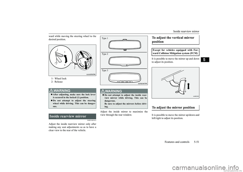
ward while moving the steering wheel to the desired position.
N00511601415
Adjust the inside rearview mirror only after making any seat adjustments so as to have a clear view to the rear of the vehicle.
Adjust the inside mirror to maximize the view through the rear window.
It is possible to move the mirror up and down to adjust its position. It is possible to move the mirror up/down and left/right to adjust its position.
1- Wheel lock 2- ReleaseWA R N I N G After adjusting, make sure the lock lever is secured in the locked (1) position. Do not attempt to adjust the steering wheel while driving. This can be danger- ous.
Inside rearview mirror
1 2
WA R N I N G Do not attempt to adjust the inside rear- view mirror while driving. This can be dangerous. Be sure to adjust the mirrors before driv-ing.Type 1 Type 2 Type 3
To adjust the vertical mirror position Except for vehicles equipped with For- ward Collision Mitigation system (FCM)To adjust the mirror position
BK0252700US.bo
ok 51 ページ 2017年10月4日 水曜日 午後4時54分
Page 140 of 417
Continuously variable transmission (CVT)
Features and controls 5-61
5
If your vehicle is equipped with the spor- tronic steering wheel paddle shifter, you can manually shift the transmission up and down. Refer to “Sports mode” on page 5-65. The transmission prevents unnecessary upshifts even when the accelerator pedal isreleased and ensures smooth driving. According to the condi
tions, the transmission
will automatically shift to a lower gear ratioto achieve stronger engine braking. This may help reduce your need to use the service brake.
N00560301104
As an additional safety precaution, modelsequipped with a CVT have a shift-lock devicethat holds the selector lever in the “P” (PARK) position. To move the selector lever from the “P” (PARK) position to anotherposition, follow the steps below. 1. Press and hold the brake pedal down. 2. Press and hold the lock button.
3. Move the selector lever to the desired position.
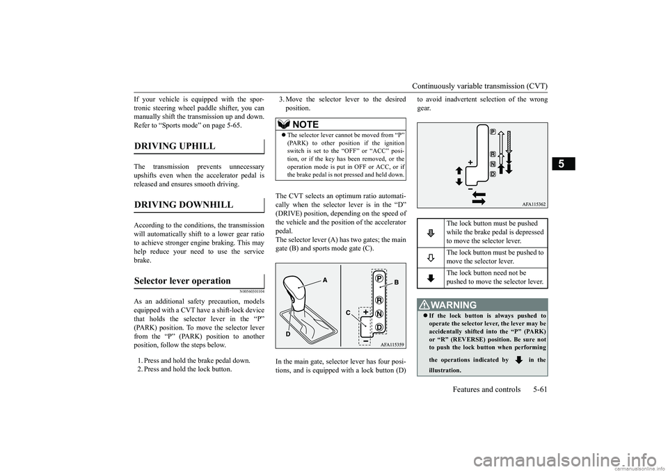
The CVT selects an optimum ratio automati- cally when the selector lever is in the “D” (DRIVE) position, depending on the speed of the vehicle and the position of the acceleratorpedal. The selector lever (A) has two gates; the main gate (B) and sports mode gate (C). In the main gate, selector lever has four posi- tions, and is equipped with a lock button (D)
to avoid inadvertent selection of the wrong gear.
DRIVING UPHILL DRIVING DOWNHILL Selector lever operation
NOTE
The selector lever cannot be moved from “P” (PARK) to other position if the ignitionswitch is set to the “OFF” or “ACC” posi- tion, or if the key has been removed, or the operation mode is put in OFF or ACC, or ifthe brake pedal is not
pressed and held down.
The lock button must be pushed while the brake pedal is depressed to move the selector lever. The lock button must be pushed to move the selector lever. The lock button need not be pushed to move the selector lever.
WA R N I N G If the lock button is always pushed to operate the selector lever, the lever may beaccidentally shifted into the “P” (PARK) or “R” (REVERSE) position. Be sure not to push the lock button when performing the operations indicated by in the illustration.
BK0252700US.bo
ok 61 ページ 2017年10月4日 水曜日 午後4時54分
Page 144 of 417
Continuously variable transmission (CVT)
Features and controls 5-65
5
N00560701108
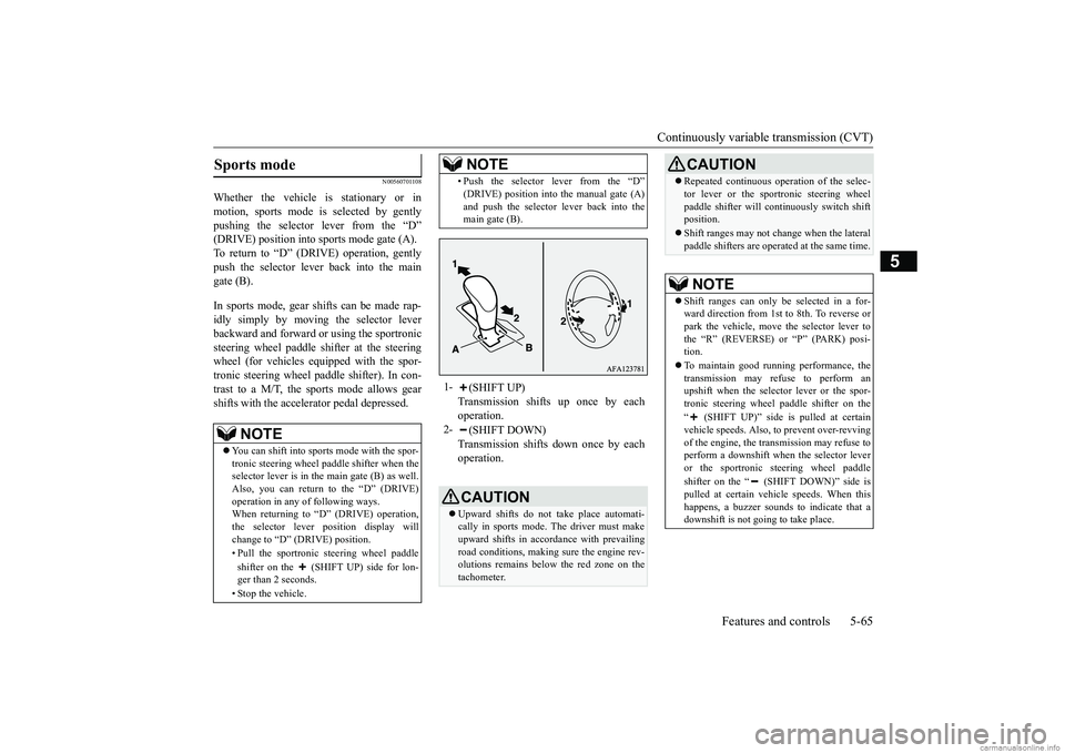
Whether the vehicle is stationary or in motion, sports mode is selected by gentlypushing the selector lever from the “D” (DRIVE) position into sports mode gate (A). To return to “D” (DRIVE) operation, gentlypush the selector lever back into the main gate (B). In sports mode, gear shifts can be made rap- idly simply by moving the selector lever backward and forward or using the sportronicsteering wheel paddle shifter at the steering wheel (for vehicles equipped with the spor- tronic steering wheel paddle shifter). In con-trast to a M/T, the sports mode allows gear shifts with the accelerator pedal depressed.Sports mode
NOTE
You can shift into sports mode with the spor- tronic steering wheel paddle shifter when theselector lever is in the main gate (B) as well. Also, you can return to the “D” (DRIVE) operation in any of following ways. When returning to “D” (DRIVE) operation, the selector lever position display willchange to “D” (DRIVE) position. • Pull the sportronic steering wheel paddle shifter on the (SHIFT UP) side for lon- ger than 2 seconds. • Stop the vehicle.
• Push the selector lever from the “D” (DRIVE) position into the manual gate (A) and push the selector lever back into the main gate (B).
1-
(SHIFT UP) Transmission shifts up once by eachoperation.
2-
(SHIFT DOWN) Transmission shifts down once by eachoperation.CAUTION Upward shifts do not take place automati- cally in sports mode. The driver must make upward shifts in accordance with prevailing road conditions, making sure the engine rev-olutions remains below the red zone on the tachometer.NOTE
Repeated continuous operation of the selec- tor lever or the sportronic steering wheel paddle shifter will continuously switch shift position. Shift ranges may not change when the lateral paddle shifters are operated at the same time.NOTE
Shift ranges can only be selected in a for- ward direction from 1st to 8th. To reverse orpark the vehicle, move the selector lever to the “R” (REVERSE) or “P” (PARK) posi- tion. To maintain good running performance, the transmission may refuse to perform anupshift when the selector lever or the spor- tronic steering wheel paddle shifter on the “ (SHIFT UP)” side is pulled at certain vehicle speeds. Also, to prevent over-revving of the engine, the transmission may refuse toperform a downshift when the selector lever or the sportronic steering wheel paddle shifter on the “ (SHIFT DOWN)” side is pulled at certain vehicle speeds. When this happens, a buzzer sounds to indicate that adownshift is not going to take place.CAUTION
BK0252700US.bo
ok 65 ページ 2017年10月4日 水曜日 午後4時54分
Page 146 of 417
S-AWC (Super-All Wheel Control) (if so equipped)
Features and controls 5-67
5
For longer waiting periods with the engine running, place the selector lever in the “N” (NEUTRAL) position and apply the parking brake, while holding the vehicle stationarywith the service brake. Prior to moving off after having stopped the vehicle, make sure that the selector lever is in“D” (DRIVE) position or Sports mode posi- tion. To park the vehicle, first bring it to a com- plete stop, firmly apply the parking brake, and then move the selector lever to the “P” (PARK) position.
If the CVT does not shift while driving, or your vehicle does not pick up enough speed when starting on an uphill slope, it may bethat there is something unusual happening in the transmission, causing a safety device to activate. Immediately have your vehiclechecked at an authorized Mitsubishi Motorsdealer or a repair facility of your choice.
N00541301091
S-AWC is an integrated vehicle dynamics control system that helps enhance driving performance, cornering performance, andvehicle stability over a wide range of driving
conditions through integrated management of the electronically controlled 4WD, the AYC (Active Yaw Control), the ABS and the ASC. The electronically controlled 4WD is a sys- tem that improves acceleration performance and stability performance by controlling front-rear distribution of driving torque withoperating the electronic control coupling arranged in the rear differential assembly.
CAUTION To avoid transmission overheating, never try to keep your vehicle stationary on a hill by using the accelerator pedal. Always apply the parking brake and/or service brake. Do not rev the engine unnecessarily while the vehicle is stationary. Unexpected acceler-ation may occur if the selector lever is in a position other than “P” (PARK) or “N” (NEUTRAL).
Parking
When the CVT makes no speed change
NOTE
When the warning display and “SLOW DOWN” or the warning display and “SERVICE REQUIRED” appear on the information screen in the multi-information display, there could be a malfunction in theCVT. Refer to “Continuously variable trans- mission (CVT): Warning display” on page 5-63.
S-AWC (Super-All Wheel Control)
(if so equipped)
CAUTION Do not over-rely on the S-AWC. Even the S- AWC cannot prevent the natural laws of physics from acting on the vehicle. This sys- tem, like any other system, has limits andcannot help you to maintain traction and con- trol of the vehicle in all circumstances. Reck- less driving can lead to accidents. It is thedriver’s responsibility to drive carefully. This means taking into account the traffic, road and environmental conditions.
Electronically Controlled 4WD
BK0252700US.bo
ok 67 ページ 2017年10月4日 水曜日 午後4時54分
Page 147 of 417
S-AWC (Super-All Wheel Control) (if so equipped) 5-68 Features and controls
5
The AYC is a system with a yaw control function, that controls the left-right driv-ing/braking force using the brakes. The yaw control function is a function that enhances vehicle cornering performance and vehicle stability with management of vehicle turning power (yaw moment) by controllingthe drive power difference of the left and right wheels and the braking force when the vehicle does not turn in response to steeringinput, such as when the steering wheel is turned quickly or when driving on slippery road.
N00542401099
Select the drive mode from the followingthree types to suit the driving conditions.
4-wheel drive operation requires special driv- ing skills. Carefully read the “4-wheel drive operation” section on page 5-70
and take care to drive
safety.
N00583000068
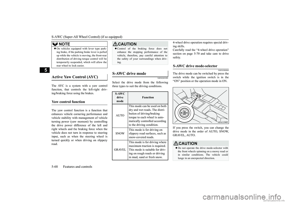
The drive mode can be switched by press theswitch while the ignition switch is in the “ON” position or the operation mode in ON. If you press the switch, you can change the drive mode in the order of AUTO, SNOW,GRAVEL, AUTO.
NOTE
On vehicles equipped with lever type park- ing brake, if the parking brake lever is pulled up while the vehicle is moving, the front-rear distribution of driving torque control will be temporarily suspended, which will allow therear wheel to lock easier.
Active Yaw Control (AYC)
Yaw control function
CAUTION Control of the braking force does not enhance the stopping performance of the vehicle, therefore, pay careful attention to the safety of your surroundings when driv- ing.
S-AWC drive mode
S-AWC drive mode
Function
AUTO
This mode can be used on both dry and wet roads. The distri-bution of driving/braking torque to each wheel is auto- matically controlled according to the driving condition.
SNOW
This mode is for driving on slippery road surfaces, such as snow-covered roads.
GRAVEL
This mode is for driving where maximum traction is required. This mode is suitable for driv- ing on rough roads or driving in mud, sand or fresh snow.
S-AWC drive mode-selector
CAUTION Do not operate the drive mode-selector with the front wheels spinning on a snowy road or in similar conditions. The vehicle could lunge in an unexpected direction.
BK0252700US.bo
ok 68 ページ 2017年10月4日 水曜日 午後4時54分
Page 148 of 417
S-AWC (Super-All Wheel Control) (if so equipped)
Features and controls 5-69
5
N00583100043
The currently selected drive mode is dis- played on the multi-information display. In addition, when the drive mode is changed, the selected mode appears on the interruptdisplay screen of the information screen in the multi-information display. The drive mode display will appear on theinformation screen for a few seconds, and then the original screen will return.
N00542501087
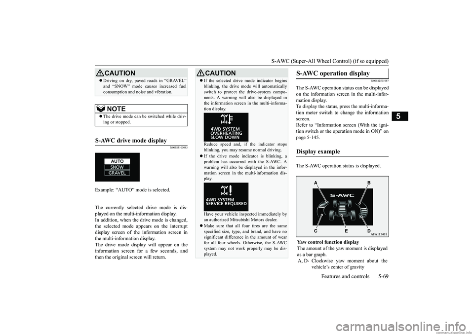
The S-AWC operation status can be displayed on the information screen in the multi-infor-mation display. To display the status, press the multi-informa- tion meter switch to change the informationscreen. Refer to “Information screen (With the igni- tion switch or the operation mode in ON)” onpage 5-145. The S-AWC operation status is displayed.
Driving on dry, paved roads in “GRAVEL” and “SNOW” mode causes increased fuel consumption and noise and vibration.NOTE
The drive mode can be switched while driv- ing or stopped.
S-AWC drive mode display
Example: “AUTO” mode is selected.
CAUTION
CAUTION If the selected drive mode indicator begins blinking, the drive mode will automatically switch to protect the drive-system compo- nents. A warning will also be displayed in the information screen in the multi-informa-tion display. Reduce speed and, if the indicator stops blinking, you may resume normal driving. If the drive mode indicator is blinking, a problem has occurred with the S-AWC. A warning will also be displayed in the infor-mation screen in the multi-information dis- play. Have your vehicle inspected immediately by an authorized Mitsubishi Motors dealer. Make sure that all four tires are the same specified size, type, and brand, and have no significant difference in the amount of wear for all four wheels. Otherwise, the S-AWCsystem may not work properly may be dis- played.
S-AWC operation display
Display example
Yaw control function display The amount of the yaw
moment is displayed
as a bar graph. A, D- Clockwise yaw moment about the
vehicle’s center of gravity
BK0252700US.bo
ok 69 ページ 2017年10月4日 水曜日 午後4時54分
Page 149 of 417
4-wheel drive operation 5-70 Features and controls
5
N00530601212
Your vehicle has been designed primarily for use on pavement. But its unique 4-wheel drive system allowsyou to occasionally travel on unpaved roads, to campgrounds, picnic sites, and similar locations.Not only does this ensure better handling on dry, paved roads but also permits better trac- tion when driving on slippery, wet or snow-covered roads and when moving out of mud. But it is not suitable for heavy off road use or towing in rough conditions.It is particularly important to note that 4- wheel drive may not give sufficient hill
climbing ability and engine braking on steep slopes. You should try to avoid driving on steep slopes. Also, you must exercise caution when drivingon sand and mud and when driving through water because sufficient traction may not be available in certain circumstances.Please avoid driving the vehicle through areas where the tires may get stuck in deep sand or mud.
B, C- Counterclockwise yaw moment
about the vehicle’s center of gravity
Traction control level display The strength of the traction control opera-tion (between the front and rear wheels) is displayed in section E of the meter as a bar graph.
WA R N I N G Always concentrate on your driving first. Keep your eyes and mind on the road. Dis-tractions while driving can lead to an acci- dent.
4-wheel drive operation
WA R N I N G Do not over-rely on the 4-wheel drive vehi- cles. Even 4-wheel drive vehicles have lim-its to the system and ability to maintain control and traction. Reckless driving may lead to accidents. Always drive carefully,taking account of the road conditions. Improperly operating this vehicle on or off-pavement can cause an accident or rollover in which you and your passengers could be seriously injured or killed.• Follow all instructions and guidelines inthe owner’s manual.• Keep your speed low and do not drivefaster than conditions.
NOTE
Driving on rough roads can be hard on a vehicle. Before you leave the pavement, be sure all scheduled maintenance and service has been done, and that you have inspected your vehicle. Pay special attention to thecondition of the tires, and check the tire pres- sures. Mitsubishi Motors is not responsible to the operator for any damage or injury caused or liability incurred by improper and negligentoperation of a vehicle. All techniques of vehicle operation depend on the skill and experience of the operator and other partici-pating parties. Any deviation from the rec- ommended operating instructions above is at their own risk. Note that the stopping distance required of the 4-wheel drive vehicle differs very littlefrom that of the front-wheel drive vehicle. When driving on a snow-covered road or a slippery, muddy surface, make sure that youkeep a sufficient distance between your vehi- cle and the one ahead of you. The driving posture should be more upright; adjust the seat to a good position for easy steering and pedal operation. Be sure to wearthe seat belt. After driving on rough roads, check each part of the vehicle and wash it thoroughly with water. Refer to the “Inspection andmaintenance following rough road opera- tion” section and “Vehicle care and Mainte- nance” sections.
BK0252700US.bo
ok 70 ページ 2017年10月4日 水曜日 午後4時54分
Page 150 of 417
4-wheel drive operation
Features and controls 5-71
5
When turning a sharp corner in “GRAVEL” position at low speed, a slight difference in steering may be experienced similar to feel- ing as if the brakes were applied. This iscalled tight corner braking and results from each of the four tires being at a different dis- tance from the corner. The phenomenon istypical of 4-wheel drive vehicles. If this occurs, either straighten out the steering wheel or change to another mode. Set the drive mode-selector to “SNOW” in accordance with the road conditions, and thengradually depress the accelerator pedal for a smooth start.
Set the drive mode-selector to “GRAVEL” and then gradually depress the accelerator pedal for a smooth start. Keep the pressure onthe accelerator pedal as constant as possible, and drive at low speed.
CAUTION Setting the drive mode-selector to “GRAVEL” and “SNOW” position to drive on dry paved road wi
ll increase fuel con-
sumption, with possible noise and vibration generation.
Turning sharp corners On snowy or icy roads
NOTE
The use of snow tires is recommended.
Maintain a safe distance between vehicles, avoid sudden braking, and use engine brak- ing (downshifting).CAUTION Avoid sudden braking, sudden acceleration and sharp turning. Skidding occurs and con- trol of the vehicle could be lost.
Driving on sandy or muddy roads
CAUTION Do not force the vehicle or drive recklessly on sandy surfaces. In comparison with nor- mal road surfaces, the engine and other drive-system components are put underexcessive strain when driving on such a sur- face. This could lead to accidents. If any of the following conditions occur while the vehicle is being driven, immedi- ately park your vehicle in a safe place andfollow these procedures:NOTE
• If the engine coolant temperature display
flashes on the information screen in the multi-information display or the engine power drops suddenly.Refer to “Engine overheating” on page 8-4.• If the “ ” warning display and “SLOW DOWN” or the “ ” warning display and “SERVICE REQUIRED” appear on the information screen in the multi-information display.Refer to “Warning display” on page 5-63.WA R N I N G When attempting to rock your vehicle out of a stuck position, be sure that the area around the vehicle is clear of people andphysical objects. The rocking motion may cause the vehicle to suddenly launch for- ward/backward, causing injury or dam-age to nearby people or objects.NOTE
Avoid sudden braking, sudden acceleration and sharp turning; such operations could result in the vehicle becoming stuck.CAUTION
BK0252700US.bo
ok 71 ページ 2017年10月4日 水曜日 午後4時54分