steering MITSUBISHI ECLIPSE CROSS 2018 (in English) Owner's Guide
[x] Cancel search | Manufacturer: MITSUBISHI, Model Year: 2018, Model line: ECLIPSE CROSS, Model: MITSUBISHI ECLIPSE CROSS 2018Pages: 417, PDF Size: 74.06 MB
Page 200 of 417
Tire pressure monitoring system (TPMS)
Features and controls 5-121
5
2. If the tire pressure monitoring system warning light remains illuminated after you have been driving for approximately20 minutes after you adjust the tire infla- tion pressure, one or more of the tires may have a puncture. Inspect the tire and if ithas a puncture, have it repaired by anauthorized Mitsubishi Motors dealer as soon as possible.
The tire pressure monitoring system may not work normally in the following circum-stances: A wireless facility or device using the same frequency is near the vehicle. Snow or ice is stuck inside the fenders and/or on the wheels. The tire inflation pressure sensor’s battery is dead. Wheels other than Mitsubishi genuine wheels are being used. Wheels that are not fitted with tire infla- tion pressure sensors are being used. Wheels whose ID co
des are not memo-
rized by the vehicle are used. Compact spare tire is fitted as a road wheel.
A window tint that affects the radio wave signals is installed.
N00532900081
If new wheels with new tire inflation pressuresensors are installed, their ID codes must beprogrammed into the tire pressure monitoring system. Have tire and wheel replacement per- formed by an authorized Mitsubishi Motorsdealer to avoid the risk of damaging the tire inflation pressure sensors. If the wheel replacement is not done by an authorizedMitsubishi Motors dealer, it is not covered by your warranty.
Once adjustments have been made, the warn- ing light will go off after a few minutes of driving.WA R N I N G If the warning light / display illuminates while you are driving, avoid hard braking,sharp steering maneuvers and high speeds. Driving with an under-inflated tireadversely affects vehicle performance and can result in an accident.CAUTION If a tire has a puncture, replace that tire with the spare tire. Driving on a punctured tire could lead to an accident. The warning light / display may not illumi- nate immediately in the event of a tire blow-out or rapid leak.NOTE
NOTE
To avoid the risk of damage to the tire infla- tion pressure sensors, have any punctured tire repaired by an authorized Mitsubishi Motors dealer. If the tire repair is not done by an authorized Mitsubishi Motors dealer, it isnot covered by your warranty. Do not use an aerosol puncture-repair spray on any tire. Such a spray could damage the tire inflation pressure sensors.Have any puncture repaired by an authorized Mitsubishi Motors dealer.
NOTE
Tire inflation pressures vary with the ambi- ent temperature. If the vehicle is subjected to large variations in ambient temperature, thetire inflation pressures may be under-inflated (causing the warning light / display come on) when the ambient temperature is relativelylow. If the warning light / display comes on, adjust the tire inflation pressure.
Whenever the tires and wheels are replaced with new ones
BK0252700US.book
121 ページ 2017年10月4日 水曜日 午後4時54分
Page 212 of 417
Multi Around Monitor (if so equipped)
Features and controls 5-133
5
N00587500058
The Multi Around Monitor can only be used when the operation mode is put in ON. When you move the selector lever to the “R” (REVERSE) position, the wide-rear-view isdisplayed on the Smartphone Link Display Audio. When you move the selector lever to any other position, the display disappears.
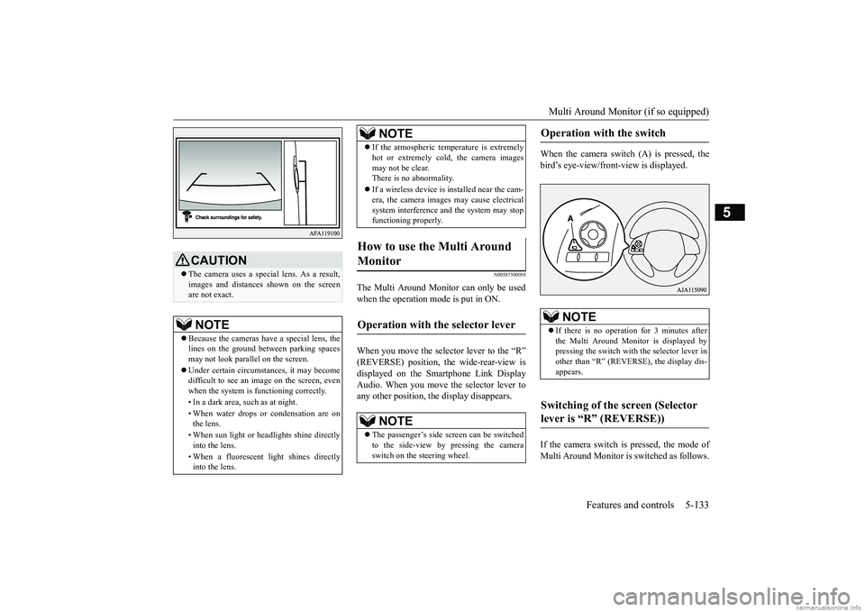
When the camera switch (A) is pressed, the bird’s eye-view/front-view is displayed. If the camera switch is pressed, the mode of Multi Around Monitor is switched as follows.
CAUTION The camera uses a special lens. As a result, images and distances shown on the screen are not exact.NOTE
Because the cameras have a special lens, the lines on the ground between parking spacesmay not look parallel on the screen. Under certain circumstances, it may become difficult to see an image on the screen, even when the system is functioning correctly. • In a dark area, such as at night. • When water drops or condensation are on the lens. • When sun light or headlights shine directly into the lens. • When a fluorescent light shines directly into the lens.
If the atmospheric temperature is extremely hot or extremely cold, the camera images may not be clear. There is no abnormality. If a wireless device is installed near the cam- era, the camera images may cause electrical system interference and the system may stopfunctioning properly.
How to use the Multi Around Monitor
Operation with the selector lever
NOTE
The passenger’s side screen can be switched to the side-view by pressing the cameraswitch on the steering wheel.NOTE
Operation with the switch
NOTE
If there is no operation for 3 minutes after the Multi Around Monitor is displayed bypressing the switch with the selector lever in other than “R” (REVERSE), the display dis- appears.
Switching of the screen (Selector lever is “R” (REVERSE))
BK0252700US.book
133 ページ 2017年10月4日 水曜日 午後4時54分
Page 213 of 417
Multi Around Monitor (if so equipped) 5-134 Features and controls
5
Wide-rear-view mode
Bird’s eye-
view/Rear-view mode
Side-view/Rear-
view mode If the camera switch is pressed, the mode of Multi Around Monitor is switched, Wide-rear-view mode
Bird’s eye-view/Front-
view mode
Side-view/Front-view mode
OFF
N00587600046
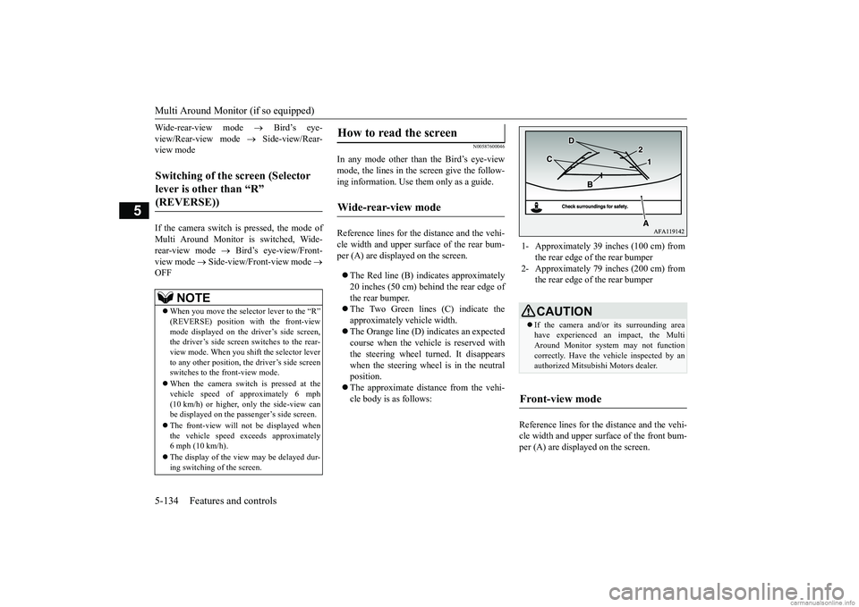
In any mode other than the Bird’s eye-view mode, the lines in the screen give the follow-ing information. Use them only as a guide. Reference lines for the distance and the vehi- cle width and upper surface of the rear bum-per (A) are displayed on the screen. The Red line (B) indicates approximately 20 inches (50 cm) behind the rear edge of the rear bumper. The Two Green lines (C) indicate the approximately vehicle width. The Orange line (D) indicates an expected course when the vehicle is reserved with the steering wheel turned. It disappears when the steering wheel is in the neutralposition. The approximate distance from the vehi- cle body is as follows:
Reference lines for the distance and the vehi- cle width and upper surface of the front bum- per (A) are displayed on the screen.
Switching of the screen (Selector lever is other than “R” (REVERSE))
NOTE
When you move the selector lever to the “R” (REVERSE) position with the front-viewmode displayed on the driver’s side screen, the driver’s side screen switches to the rear- view mode. When you shift the selector leverto any other position, the driver’s side screen switches to the front-view mode. When the camera switch is pressed at the vehicle speed of approximately 6 mph (10 km/h) or higher, only the side-view can be displayed on the passenger’s side screen. The front-view will not be displayed when the vehicle speed exceeds approximately 6 mph (10 km/h). The display of the view may be delayed dur- ing switching of the screen.
How to read the screen
Wide-rear-view mode
1- Approximately 39 inches (100 cm) from
the rear edge of the rear bumper
2- Approximately 79 inches (200 cm) from
the rear edge of the rear bumperCAUTION If the camera and/or its surrounding area have experienced an impact, the MultiAround Monitor system may not function correctly. Have the vehicle inspected by an authorized Mitsubishi Motors dealer.
Front-view mode
BK0252700US.book
134 ページ 2017年10月4日 水曜日 午後4時54分
Page 214 of 417
Multi Around Monitor (if so equipped)
Features and controls 5-135
5
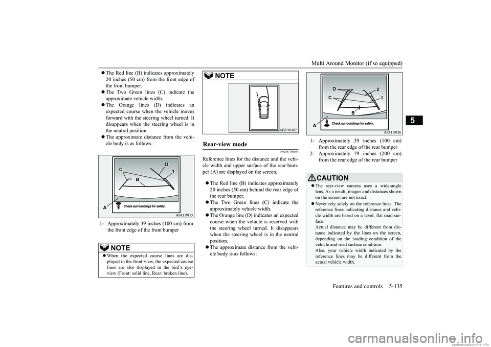
The Red line (B) indicates approximately 20 inches (50 cm) from the front edge of the front bumper. The Two Green lines (C) indicate the approximate vehicle width. The Orange lines (D) indicates an expected course when the vehicle movesforward with the steering wheel turned. It disappears when the steering wheel is in the neutral position. The approximate distance from the vehi- cle body is as follows:
N00587700034
Reference lines for the distance and the vehi-cle width and upper surface of the rear bum-per (A) are displayed on the screen. The Red line (B) indicates approximately 20 inches (50 cm) behind the rear edge of the rear bumper. The Two Green lines (C) indicate the approximately vehicle width. The Orange line (D) indicates an expected course when the vehicle is reserved with the steering wheel turned. It disappears when the steering wheel is in the neutralposition. The approximate distance from the vehi- cle body is as follows:
1- Approximately 39 inches (100 cm) from
the front edge of the front bumperNOTE
When the expected course lines are dis- played in the front-view, the expected courselines are also displayed in the bird’s eye- view (Front: solid line, Rear: broken line).
Rear-view mode
NOTE
1- Approximately 39 inches (100 cm)
from the rear edge of the rear bumper
2- Approximately 79 inches (200 cm)
from the rear edge of the rear bumperCAUTION The rear-view camera uses a wide-angle lens. As a result, images and distances shownon the screen are not exact. Never rely solely on the reference lines. The reference lines indicating distance and vehi- cle width are based on a level, flat road sur- face.Actual distance may be different from dis- tance indicated by the lines on the screen, depending on the loading condition of thevehicle and road surface condition. Also, your vehicle widt
h indicated by the
reference lines may be different from theactual vehicle width.
BK0252700US.book
135 ページ 2017年10月4日 水曜日 午後4時54分
Page 231 of 417
Multi-information display 5-152 Features and controls
5
N00578800055
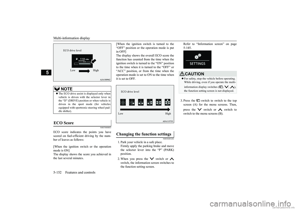
ECO score indicates the points you have scored on fuel-efficient driving by the num- ber of leaves as follows: [When the ignition switch or the operation mode is ON]The display shows the score you achieved in the last several minutes.
[When the ignition switch is turned to the “OFF” position or the operation mode is put in OFF] The display shows the overall ECO score thefunction has counted from the time when the ignition switch is turned to the “ON” position to the time when it is turned to the “OFF” or“ACC” position, or from the time when the operation mode is set to ON to the time when it is set to OFF.
N00556801283
1. Park your vehicle in a safe place.Firmly apply the parking brake and movethe selector lever into the “P” (PARK) position. 2. When you press
the switch or
switch, the information screen switches to the function setting screen.
Refer to “Information screen” on page 5-145. 3. Press the switch to switch to the top screen (A) for the menu screens. Then, press the switch or switch to switch to the menu screens (B).
NOTE
The ECO drive assist is displayed only when vehicle is driven with the selector lever in the “D” (DRIVE) position or when vehicle isdriven in the sport mode (for vehicles equipped with sportronic steering wheel pad- dle shifter).
ECO Score
ECO drive level
Low High
Changing the function settings
ECO drive level Low High
CAUTION For safety, stop the vehicle before operating. While driving, even if you operate the multi- information display switches ( , , ), the function setting scr
een is not displayed.
BK0252700US.book
152 ページ 2017年10月4日 水曜日 午後4時54分
Page 239 of 417
Indicator light, warning light, an
d information screen display list
5-160 Features and controls
5
N00557701090 N00557801352
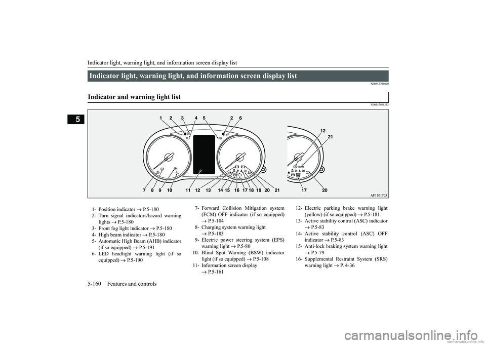
Indicator light, warning light, and information screen display list Indicator and warning light list 1- Position indicator
P.5-180
2- Turn signal indicators/hazard warning
lights
P.5-180
3- Front fog light indicator
P.5-180
4- High beam indicator
P.5-180
5- Automatic High Beam (AHB) indicator
(if so equipped)
P.5-191
6- LED headlight warning light (if so
equipped)
P.5-190
7- Forward Collision Mitigation system
(FCM) OFF indicator (if so equipped) P.5-104
8- Charging system warning light
P.5-183
9- Electric power steering system (EPS)
warning light
P.5-80
10- Blind Spot Warning (BSW) indicator
light (if so equipped)
P.5-108
11- Information screen display
P.5-161
12- Electric parking brake warning light
(yellow) (if so equipped)
P.5-181
13- Active stability control (ASC) indicator
P.5-83
14- Active stability control (ASC) OFF
indicator
P.5-83
15- Anti-lock braking system warning light
P.5-79
16- Supplemental Restraint System (SRS)
warning light
P. 4-36
BK0252700US.book
160 ページ 2017年10月4日 水曜日 午後4時54分
Page 243 of 417
Indicator light, warning light, an
d information screen display list
5-164 Features and controls
5
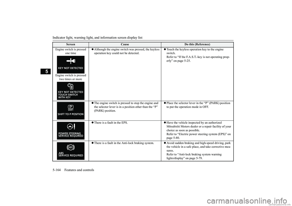
Engine switch is pressed
one time
Engine switch is pressed
two times or more
Although the engine switch was pressed, the keyless operation key could not be detected.
Touch the keyless operation key to the engine switch. Refer to “If the F.A.S.T.-key is not operating prop-erly” on page 5-25.
The engine switch is pressed to stop the engine and the selector lever is in a position other than the “P” (PARK) position.
Place the selector lever in the “P” (PARK) position to put the operation mode in OFF.
There is a fault in the EPS.
Have the vehicle inspected by an authorized Mitsubishi Motors dealer or a repair facility of your choice as soon as possible. Refer to “Electric power
steering system (EPS)” on
page 5-80.
There is a fault in the Anti-lock braking system.
Avoid sudden braking and high-speed driving, park the vehicle in a safe place, and take corrective mea- sures. Refer to “Anti-lock braking system warning lights/display” on page 5-79.
Screen
Cause
Do this (Reference)
BK0252700US.book
164 ページ 2017年10月4日 水曜日 午後4時54分
Page 276 of 417
Hazard warning flasher switch Features and controls 5-197
5
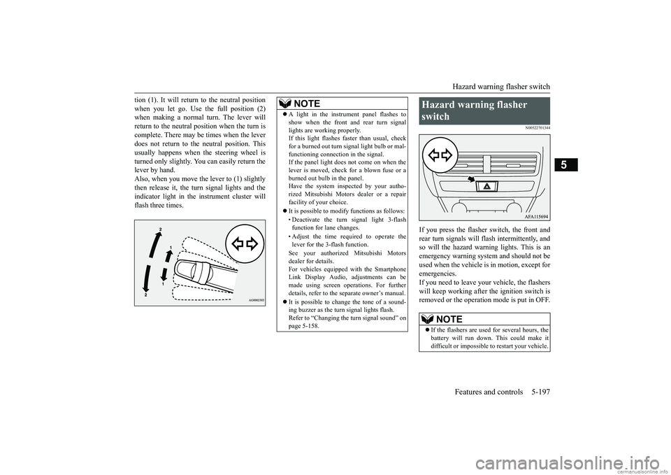
tion (1). It will return to the neutral position when you let go. Use the full position (2) when making a normal turn. The lever will return to the neutral position when the turn iscomplete. There may be times when the lever does not return to the neutral position. This usually happens when the steering wheel isturned only slightly. You can easily return the lever by hand. Also, when you move the lever to (1) slightlythen release it, the turn signal lights and theindicator light in the instrument cluster will flash three times.
N00522701344
If you press the flasher switch, the front and rear turn signals will flash intermittently, and so will the hazard warning lights. This is an emergency warning system and should not beused when the vehicle is in motion, except foremergencies. If you need to leave your vehicle, the flashers will keep working after the ignition switch isremoved or the operation mode is put in OFF.
NOTE
A light in the instrument panel flashes to show when the front and rear turn signal lights are working properly. If this light flashes faster than usual, check for a burned out turn signal light bulb or mal-functioning connection in the signal. If the panel light does not come on when the lever is moved, check for a blown fuse or aburned out bulb in the panel. Have the system inspected by your autho- rized Mitsubishi Motors dealer or a repairfacility of your choice. It is possible to modify functions as follows: • Deactivate the turn signal light 3-flash function for lane changes. • Adjust the time required to operate the lever for the 3-flash function. See your authorized Mitsubishi Motors dealer for details.For vehicles equipped with the Smartphone Link Display Audio, adjustments can be made using screen operations. For furtherdetails, refer to the separate owner’s manual. It is possible to change the tone of a sound- ing buzzer as the turn signal lights flash. Refer to “Changing the turn signal sound” on page 5-158.
Hazard warning flasher switch
NOTE
If the flashers are used for several hours, the battery will run down. This could make it difficult or impossible to restart your vehicle.
BK0252700US.book
197 ページ 2017年10月4日 水曜日 午後4時54分
Page 284 of 417
Heated steering wheel switch (if so equipped)
Features and controls 5-205
5
N00589100045
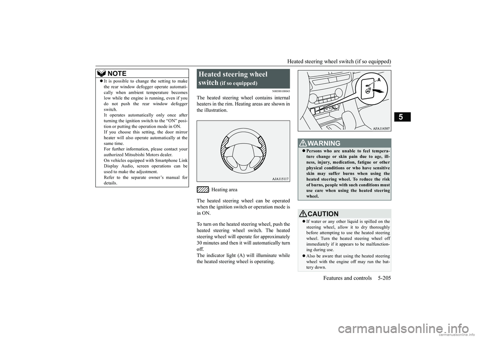
The heated steering wheel contains internal heaters in the rim. Heating areas are shown inthe illustration.
: Heating area
The heated steering wheel can be operated when the ignition switch or operation mode is in ON. To turn on the heated steering wheel, push the heated steering wheel switch. The heatedsteering wheel will operate for approximately 30 minutes and then it will automatically turn off.The indicator light (A) will illuminate while the heated steering wheel is operating.
It is possible to change the setting to make the rear window defogger operate automati- cally when ambient temperature becomes low while the engine is running, even if you do not push the rear window defoggerswitch. It operates automatically only once after turning the ignition switch to the “ON” posi-tion or putting the operation mode in ON. If you choose this setting, the door mirror heater will also operate automatically at thesame time. For further information, please contact your authorized Mitsubishi Motors dealer.On vehicles equipped with Smartphone Link Display Audio, screen operations can be used to make the adjustment.Refer to the separate owner’s manual for details.NOTE
Heated steering wheel switch
(if so equipped)
WA R N I N G Persons who are unable to feel tempera- ture change or skin pain due to age, ill- ness, injury, medication, fatigue or other physical conditions or who have sensitiveskin may suffer burns when using the heated steering wheel. To reduce the risk of burns, people with such conditions mustuse care when using the heated steering wheel.CAUTION If water or any other
liquid is spilled on the
steering wheel, allow it to dry thoroughly before attempting to use the heated steering wheel. Turn the heated steering wheel offimmediately if it appears to be malfunction- ing during use. Also be aware that using the heated steering wheel with the engine off may run the bat- tery down.
BK0252700US.book
205 ページ 2017年10月4日 水曜日 午後4時54分
Page 285 of 417
Horn switch 5-206 Features and controls
5
N00523801195
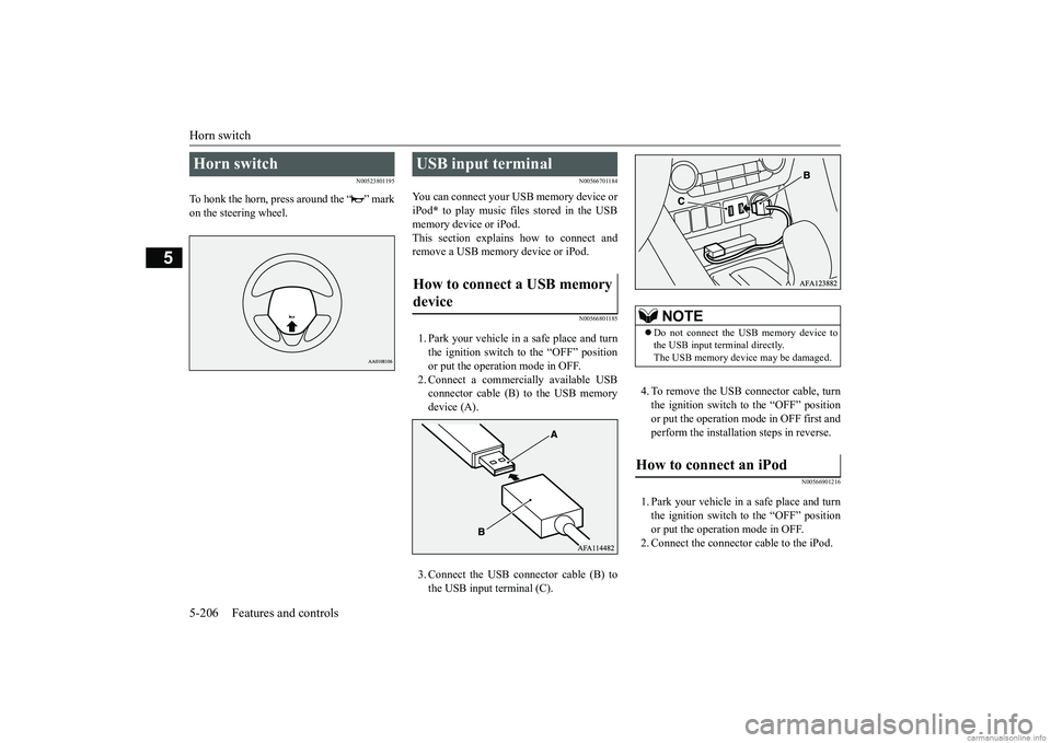
To honk the horn, press around the “ ” mark on the steering wheel.
N00566701184
You can connect your USB memory device or iPod
* to play music files stored in the USB
memory device or iPod. This section explains how to connect and remove a USB memory device or iPod.
N00566801185
1. Park your vehicle in a safe place and turnthe ignition switch to the “OFF” position or put the operation mode in OFF. 2. Connect a commercially available USBconnector cable (B) to the USB memory device (A). 3. Connect the USB connector cable (B) to the USB input terminal (C).
4. To remove the USB connector cable, turn the ignition switch to the “OFF” positionor put the operation mode in OFF first and perform the installation steps in reverse.
N00566901216
1. Park your vehicle in a safe place and turn the ignition switch to the “OFF” positionor put the operation mode in OFF. 2. Connect the connector cable to the iPod.
Horn switch
USB input terminal How to connect a USB memory device
NOTE
Do not connect the USB memory device to the USB input terminal directly. The USB memory device may be damaged.
How to connect an iPod
BK0252700US.book
206 ページ 2017年10月4日 水曜日 午後4時54分