Lights MITSUBISHI ECLIPSE CROSS 2018 (in English) Manual PDF
[x] Cancel search | Manufacturer: MITSUBISHI, Model Year: 2018, Model line: ECLIPSE CROSS, Model: MITSUBISHI ECLIPSE CROSS 2018Pages: 417, PDF Size: 74.06 MB
Page 316 of 417
Trailer towing
Driving safety 6-13
6
Your vehicle will need service more often when you’re towing a trailer. Refer to “WAR- RANTY AND MAINTENANCE MAN- UAL”. Especially important in traileroperation are automatic transaxle fluid, engine oil, rear axle oil, belt, cooling system and brake system. Each of these is covered inthis manual.For details, please refer to the “Vehicle care and maintenance” section. Check periodically to see that all hitch nutsand bolts are tight. Mitsubishi Motors recommends that any trailer having a total weight of 1,250 lb (567 kg) or more be equipped with its own electric or surge-type brakes. If you choose electric brakes, be sure they are electrically actuated. Do not attempt to tap into your vehicle’s hydraulic system. No mat- ter how successful it may seem, any attemptto attach trailer brakes to your vehicle’s hydraulic system will lower braking effec- tiveness and create a potential hazard.
Trailer lights and equipment must comply with federal, state, and local regulations.Check with your local recreational vehicle dealer for the requirements in your area, and use only equipment designed for your vehi-cle. Since lighting and wiring vary by trailer type and brand, you should have a qualified tech- nician install a suitable connector between the vehicle and the trailer. Improper equipment orinstallation can cause damage to your vehi- cle’s electrical system and affect your vehicle warranty. Many states and Canadian provinces require special outside mirrors when towing a trailer.Even if not required, you should install spe- cial mirrors if you cannot clearly see behind you, or if the trailer creates a blind spot. Ask your trailer sales or rental agency if any other items are recommended or required for your towing situation.
Towing a trailer requires a certain amount of experience. Before setting out for the open road, you’llwant to get to know your trailer. Acquaint
Maintenance when trailer tow- ing Trailer brakes
Trailer lights Additional trailer equipment
Operating hints
WA R N I N G If you have a rear window open and you tow a trailer with your vehicle, carbon monoxide gas which you cannot see or smell could come into your vehicle. It cancause unconsciousness or death. Refer to “Exhaust system” on page 9-22. To maximize your safety when towing atrailer:• Have your exhaust system inspected forleaks, and make necessary repairs before starting on your trip.• Keep the rear windows closed.• If exhaust does come into your vehicle through a window or another opening, drive with your front, main heating or cooling system on and with the blower onany speed. This will bring fresh, outside air into your vehicle. Do not use recircu- lation because it only recirculates the airinside your vehicle. Refer to “Air selec- tion switch” on page 7-9.
Driver preparation
BK0252700US.bo
ok 13 ページ 2017年10月4日 水曜日 午後4時54分
Page 345 of 417
If the vehicle breaks down 8-2 For emergencies
8
N00836301230
If your vehicle breaks down on the road, move to the shoulder and turn on the hazardwarning flashers. If there is no shoulder, or the shoulder is not safe, drive in the right lane slowly with the hazard
lights flashing, until
you come to a safe stopping place. Keep the flashers flashing. If the engine stops, there will be no power assist to the steering and brakes, making these difficult to use. The brake booster will not work, so the brakes will not grip well. The brake pedalwill be harder to press than usual. Since there is no power steering assist, the steering wheel will be hard to turn.
Get help from your passengers, bystanders, etc. to push the vehicl
e and move it to a safe
area.
N00860700029
If the operation mode cannot be changed to OFF, perform the following procedure. 1. Move the selector lever to the “P” (PARK) position, and then change theoperation mode to OFF. 2. One of the other causes could be low bat- tery voltage. If this occurs, the keylessentry system, keyless operation function, and steering lock will also not operate. Contact an authorized Mitsubishi Motorsdealer or a repair facility of your choice.
N00836401840
If the engine cannot be started because thebattery is weak or dead, you can start it with the battery from another vehicle using jumper cables.
1. Take off any metal jewelry such as watch bands or bracelets that might create anaccidental electrical contact. 2. Position the vehicles close enough together so that the jumper cables canreach, but be sure the vehicles aren’t touching each other. 3. Set the parking brake firmly on your vehi- cle and move the selector lever into the “P” (PARK) position.
If the vehicle breaks down If the engine stops/fails When the engine fails at the intersection
If the operation mode can- not be changed to OFF (vehicles equipped with the F.A.S.T.-key) Jump-starting the engine
WA R N I N G To reduce the risk of igniting flammable gas that may be emitted from the battery, carefully read this section before jump- starting the vehicle. Do not try to start your vehicle by pushing or towing. This can cause an accident resulting in serious injury or death andcan damage the vehicle.NOTE
Do not use jumper cables if they have dam- age or corrosion.CAUTION Check the other vehicle. It must have a 12- volt battery. If the other system isn’t 12-volt, both systems can be damaged.
BK0252700US.bo
ok 2 ページ 2017年10月4日 水曜日 午後4時54分
Page 346 of 417
Jump-starting the engine For emergencies 8-3
8
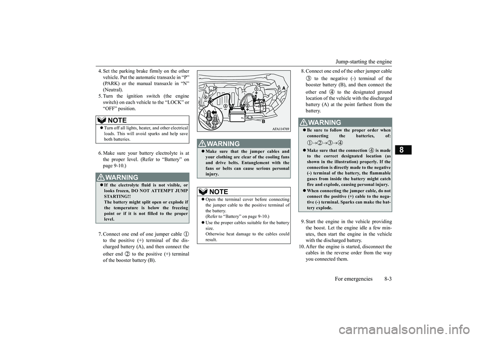
4. Set the parking brake firmly on the other vehicle. Put the automatic transaxle in “P” (PARK) or the manual transaxle in “N” (Neutral).5. Turn the ignition switch (the engine switch) on each vehicle to the “LOCK” or “OFF” position. 6. Make sure your battery electrolyte is at the proper level. (Refer to “Battery” on page 9-10.) 7. Connect one end of one jumper cable to the positive (+) terminal of the dis- charged battery (A), and then connect the other end to the positive (+) terminal of the booster battery (B).
8. Connect one end of the other jumper cable
to the negative (-) terminal of the booster battery (B), and then connect the other end to the designated ground location of the vehicle with the discharged battery (A) at the point farthest from thebattery. 9. Start the engine in the vehicle providing the boost. Let the engine idle a few min- utes, then start the engine in the vehicle with the discharged battery.
10. After the engine is started, disconnect the
cables in the reverse order from the way you connected them.
NOTE
Turn off all lights, heater, and other electrical loads. This will avoid sparks and help save both batteries.WA R N I N G If the electrolyte fluid is not visible, or looks frozen, DO NOT ATTEMPT JUMP STARTING!! The battery might split open or explode ifthe temperature is below the freezing point or if it is not filled to the proper level.
WA R N I N G Make sure that the jumper cables and your clothing are clear of the cooling fans and drive belts. Entanglement with the fans or belts can cause serious personalinjury.NOTE
Open the terminal cover before connecting the jumper cable to the positive terminal ofthe battery. (Refer to “Battery” on page 9-10.) Use the proper cables suitable for the battery size. Otherwise heat damage to the cables couldresult.
WA R N I N G Be sure to follow the proper order when connecting the batteries, of:
Make sure that the connection is made to the correct designated location (as shown in the illustration) properly. If the connection is directly made to the negative(-) terminal of the battery, the flammable gases from inside the battery might catch fire and explode, causing personal injury. When connecting the jumper cable, do not connect the positive (+) cable to the nega-tive (-) terminal. Sparks can make the bat- tery explode.
BK0252700US.bo
ok 3 ページ 2017年10月4日 水曜日 午後4時54分
Page 349 of 417

How to change a tire 8-6 For emergencies
8
1. Retract the jack, then return it to its origi- nal position.2. Extend the jack and firmly secure it in its storage area, then lo
wer the luggage floor
board.
N00836901904
Before changing a tire, first stop your vehiclein a safe, flat location. 1. Park the vehicle on level and stable ground. 2. Set the parking brake firmly. 3. Move the selector lever to the “P”(PARK) position and turn the ignitionswitch (the engine switch) to the “OFF” position. 4. Turn on the hazard warning flashers andset up a warning sign, such as a warning triangle or flashing signal lights, at an adequate distance from the vehicle, andhave all your passengers leave the vehicle. 5. To prevent the vehicle from rolling when it is raised on the jack, place chocks orblocks (A) at the tire that is diagonally opposite from the tire (B) you are chang- ing.
6. Get the jack, bar and wheel nut wrench ready. (Refer to “Jack and tools” on page 8-5.)
To s t o r e
To r e t r a c tTo r e t r a c t
To e x t e n d
How to change a tire
WA R N I N G Be sure to apply chocks or blocks to the correct tire when jacking up the vehicle. If the vehicle moves while jacked up, thejack could slip out of position, leading to an accident.NOTE
The chocks shown in the illustration do not come with your vehicle. It is recommended that you purchase chocks or blocks and keep them in the vehicle for use if needed. If chocks or blocks are not available, use stones or any other objects that are largeenough to hold the wheel in position.
BK0252700US.bo
ok 6 ページ 2017年10月4日 水曜日 午後4時54分
Page 381 of 417
Fuses 9-24 Vehicle care and maintenance
9
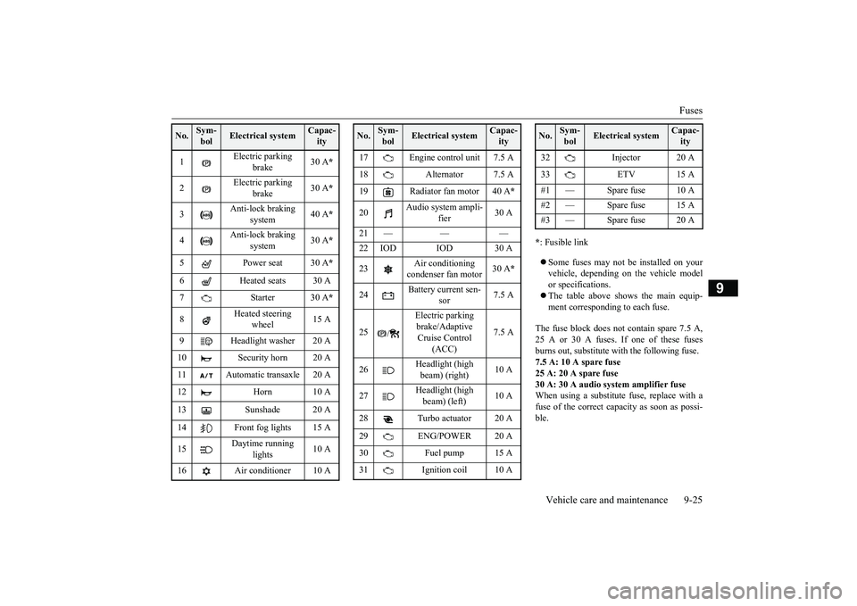
* : Fusible link Some fuses may not be installed on your vehicle, depending on the vehicle model or specifications. The table above shows the main equip- ment corresponding to each fuse.
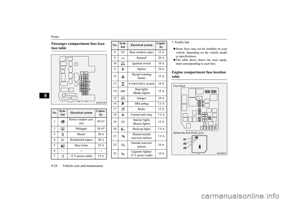
Passenger compartment fuse loca- tion table No.
Sym- bol
Electrical system
Capac-ity
1
Power window con-
trol
30 A
*
2 Defogger 30 A
*
3 Heater 30 A 4 Windshield wipers 30 A 5 Door locks 25 A 6— — — 7 12 V power outlet 15 A
8 Rear window wiper 15 A 9 Sunroof 20 A 10 Ignition switch 10 A 11 Option 10 A 12
Hazard warning
flasher
15 A
13 4-wheel drive system 10 A14
Stop lights (Brake lights)
15 A
15 Gauges 10 A 16 SRS airbag 7.5 A 17 Radio 15 A 18 Control unit relay 7.5 A 19
Interior lights (Room lights)
15 A
20 Back-up lights 7.5 A21
Heated outside rearview mirrors
7.5 A
22
Outside rearview
mirrors
10 A
23
Cigarette lighter/ 12 V power outlet
15 A
No.
Sym- bol
Electrical system
Capac-ity
Engine compartment fuse location table Behind the fuse block cover Fuse block
BK0252700US.bo
ok 24 ページ 2017年10月4日 水曜日 午後4時54分
Page 382 of 417
Fuses
Vehicle care and maintenance 9-25
9
* : Fusible link Some fuses may not be installed on your vehicle, depending on the vehicle model or specifications. The table above shows the main equip- ment corresponding to each fuse.
The fuse block does not contain spare 7.5 A, 25 A or 30 A fuses. If one of these fusesburns out, substitute with the following fuse.7.5 A: 10 A spare fuse 25 A: 20 A spare fuse 30 A: 30 A audio system amplifier fuseWhen using a substitute fuse, replace with a fuse of the correct capacity as soon as possi- ble.
No.
Sym- bol
Electrical system
Capac-ity
1
Electric parking
brake
30 A
*
2
Electric parking
brake
30 A
*
3
Anti-lock braking
system
40 A
*
4
Anti-lock braking
system
30 A
*
5 Power seat 30 A
*
6 Heated seats 30 A 7Starter30 A
*
8
Heated steering
wheel
15 A
9 Headlight washer 20 A 10 Security horn 20 A 11 Automatic transaxle 20 A 12 Horn 10 A 13 Sunshade 20 A14 Front fog lights 15 A 15
Daytime running
lights
10 A
16 Air conditioner 10 A
17 Engine control unit 7.5 A 18 Alternator 7.5 A 19 Radiator fan motor 40 A
*
20
Audio system ampli-
fier
30 A
21 — — — 22 IOD IOD 30 A 23
Air conditioning condenser fan motor
30 A
*
24
Battery current sen-
sor
7.5 A
25
/
Electric parking brake/Adaptive Cruise Control
(ACC)
7.5 A
26
Headlight (high beam) (right)
10 A
27
Headlight (high beam) (left)
10 A
28 Turbo actuator 20 A 29 ENG/POWER 20 A 30 Fuel pump 15 A31 Ignition coil 10 ANo.
Sym- bol
Electrical system
Capac-ity
32 Injector 20 A 33 ETV 15 A #1 — Spare fuse 10 A #2 — Spare fuse 15 A#3 — Spare fuse 20 ANo.
Sym- bol
Electrical system
Capac-ity
BK0252700US.bo
ok 25 ページ 2017年10月4日 水曜日 午後4時54分
Page 384 of 417
Replacement of light bulbs
Vehicle care and maintenance 9-27
9
N00942901418
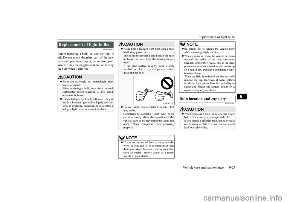
Before replacing a bulb, be sure the light is off. Do not touch the glass part of the newbulb with your bare fingers; the oil from your skin will stay on the glass and dim or destroy the bulb when it gets hot.
N00943001197
Replacement of light bulbs
CAUTION Bulbs are extremely hot immediately after being turned off.When replacing a bulb, wait for it to cool sufficiently before touching it. You could otherwise be burned. Handle halogen light bulb with care. The gas inside a halogen light bulb is highly pressur-ized, so dropping, knocking, or scratching a halogen light bulb can cause it to shatter.
Never hold a halogen light bulb with a bare hand, dirty glove, etc. The oil from your hand could cause the bulb to break the next time the headlights are used.If the glass surface is dirty, clean it with alcohol and let it dry completely before installing the bulb. Do not install commercially available LED type bulbs.Commercially available LED type bulbs could adversely affect the operation of the vehicle, such as by preventing the lights andother vehicle equipment from operating properly.NOTE
If you are unsure of how to carry out the work as required, it is recommended that these procedures be carried out by an autho- rized Mitsubishi Motors dealer or a repairfacility of your choice.CAUTION
Be careful not to scratch the vehicle body when removing a light and lens. When it rains, or when the vehicle has been washed, the inside of the lens sometimesbecomes temporarily foggy. This is the same phenomenon as when window glass mists up on a humid day, and does not indicate a func-tional problem. When the light is switched on, the heat will remove the fog. However, if water gathersinside the light, please have it checked by an authorized Mitsubishi Motors dealer or a repair facility of your choice.
Bulb location and capacity
CAUTION When replacing a bulb, be sure to use a new bulb of the same type, wattage, and color.If you install a different bulb, the bulb could malfunction or fail to come on and could lead to a vehicle fire.NOTE
BK0252700US.bo
ok 27 ページ 2017年10月4日 水曜日 午後4時54分
Page 385 of 417
Replacement of light bulbs
9-28 Vehicle care and maintenance
9
N00950302102
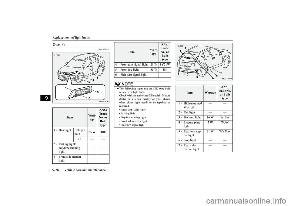
Outside
Item
Wa t t -age
ANSI
Tr a d e
No. or
Bulb type
1 - Headlight Halogen bulb55 W HIR2
LED — —
2 - Parking light/ Daytime running
light ——
3 - Front side-marker light ——
Front
4 - Front turn signal light 21 W PY21W
5 - Front fog light 35 W H8
6 - Side turn signal light — —
NOTE
The following lights use an LED type bulb
instead of a light bulb.
Check with an authorized Mitsubishi Motors
dealer or a repair facility of your choice
when either light needs to be repaired or
replaced.
• Headlight (LED type)
• Parking light
• Daytime running light
• Front side-marker light
• Side turn signal light
Item
Wa t t - age
ANSI
Tr a d e
No. or Bulb type
Item
Wattage
ANSI
trade No. or Bulb
type
1 - High-mounted stop light ——
2 - Tail light — —
3 - Back-up light 16 W W16W
4 - License plate light 5 W W5W
5 - Rear turn sig- nal light 21 W WY21W
6 - Stop light — —
7 - Rear side- marker light ——
Rear
BK0252700US.bo
ok 28 ページ 2017年10月5日 木曜日 午後6時49分
Page 386 of 417
Replacement of light bulbs
Vehicle care and maintenance 9-29
9
N00950401757
N00901801229
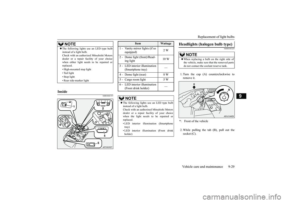
1. Turn the cap (A) counterclockwise to remove it. 2. While pulling the tab (B), pull out the socket (C).
NOTE
The following lights use an LED type bulb instead of a light bulb. Check with an authorized Mitsubishi Motors dealer or a repair
facility of your choice
when either light needs to be repaired orreplaced. • High-mounted stop light• Tail light • Stop light • Rear side-marker light
Inside
Item
Wattage
1 - Vanity mirror lights (if so
equipped)
2 W
2 - Dome light (front)/Read-
ing light
10 W
3 - LED interior illumination
(Smartphone tray)
—
4 - Dome light (rear) 8 W 5 - Cargo room light 5 W6 - LED interior illumination
(Front drink holder)
—
NOTE
The following lights use an LED type bulb instead of a light bulb. Check with an authorized Mitsubishi Motors dealer or a repair facility of your choice when the light needs to be repaired orreplaced. • LED interior illumination (Smartphone tray) • LED interior illumination (Front drink holder)
Headlights (halogen bulb type)
NOTE
When replacing a bulb on the right side of the vehicle, make sure that the removed parts do not contact the coolant reserve tank.
* : Front of the vehicle
BK0252700US.bo
ok 29 ページ 2017年10月4日 水曜日 午後4時54分
Page 387 of 417
Replacement of light bulbs 9-30 Vehicle care and maintenance
9
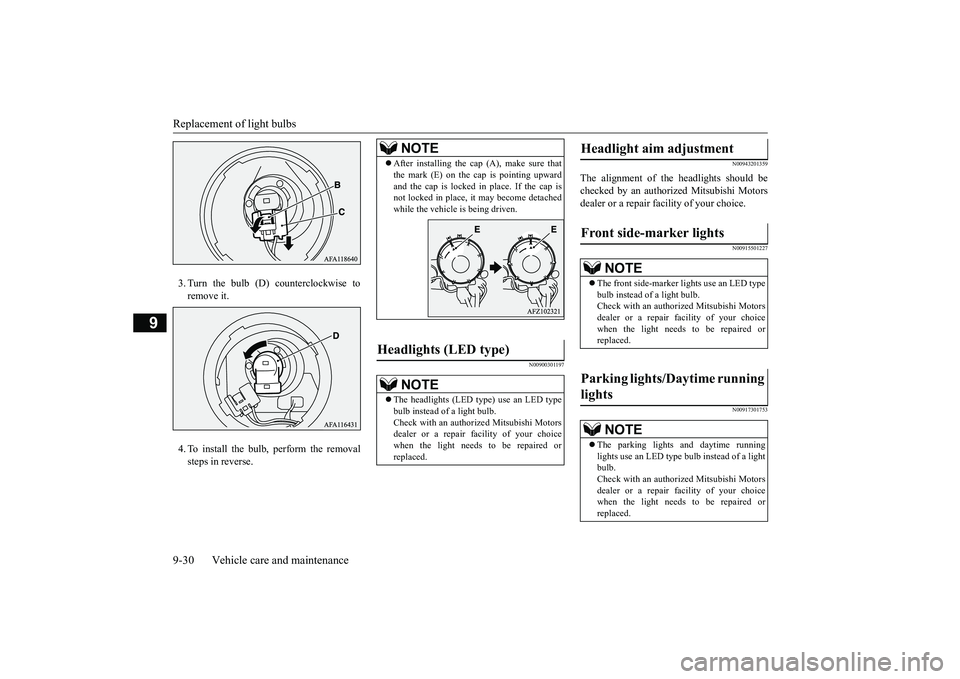
3. Turn the bulb (D) counterclockwise to remove it. 4. To install the bulb, perform the removal steps in reverse.
N00900301197
N00943201359
The alignment of the headlights should be checked by an authorized Mitsubishi Motorsdealer or a repair facility of your choice.
N00915501227 N00917301753
NOTE
After installing the cap (A), make sure that the mark (E) on the cap is pointing upward and the cap is locked in place. If the cap is not locked in place, it may become detached while the vehicle is being driven.
Headlights (LED type)
NOTE
The headlights (LED type) use an LED type bulb instead of a light bulb. Check with an authorized Mitsubishi Motors dealer or a repair
facility of your choice
when the light needs to be repaired or replaced.
Headlight aim adjustment Front side-marker lights
NOTE
The front side-marker lights use an LED type bulb instead of a light bulb.Check with an authorized Mitsubishi Motors dealer or a repair
facility of your choice
when the light needs to be repaired orreplaced.
Parking lights/Daytime running lights
NOTE
The parking lights and daytime running lights use an LED type bulb instead of a lightbulb. Check with an authorized Mitsubishi Motors dealer or a repair
facility of your choice
when the light needs to be repaired or replaced.
BK0252700US.bo
ok 30 ページ 2017年10月4日 水曜日 午後4時54分