lock MITSUBISHI ECLIPSE CROSS 2019 (in English) Repair Manual
[x] Cancel search | Manufacturer: MITSUBISHI, Model Year: 2019, Model line: ECLIPSE CROSS, Model: MITSUBISHI ECLIPSE CROSS 2019Pages: 423, PDF Size: 75.41 MB
Page 123 of 423
Power window control 5-40 Features and controls
5
N00548701153
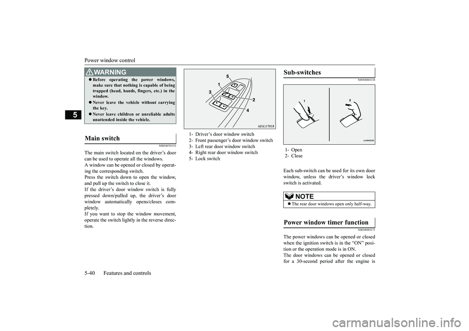
The main switch located on the driver’s door can be used to operate all the windows. A window can be opened or closed by operat-ing the corresponding switch. Press the switch down to open the window, and pull up the switch to close it.If the driver’s door window switch is fully pressed down/pulled up, the driver’s door window automatically opens/closes com-pletely. If you want to stop the window movement, operate the switch lightly in the reverse direc-tion.
N00548801138
Each sub-switch can be used for its own door window, unless the driver’s window lock switch is activated.
N00548901171
The power windows can be opened or closed when the ignition switch is in the “ON” posi- tion or the operation mode is in ON.The door windows can be opened or closed for a 30-second period after the engine is
WA R N I N G Before operating the power windows, make sure that nothing is capable of being trapped (head, hands, fingers, etc.) in the window. Never leave the vehicle without carrying the key. Never leave children or unreliable adults unattended inside the vehicle.
Main switch
1- Driver’s door window switch 2- Front passenger’s door window switch 3- Left rear door window switch 4- Right rear door window switch5- Lock switch
Sub-switches 1- Open 2- Close
NOTE
The rear door windows open only half-way.
Power window timer function
BK0266800US.bo
ok 40 ページ 2018年6月27日 水曜日 午後5時6分
Page 124 of 423
Power window control
Features and controls 5-41
5
stopped. However, once the driver’s door or the front passenger’s door is opened, the power windows cannot be operated.
N00549001182
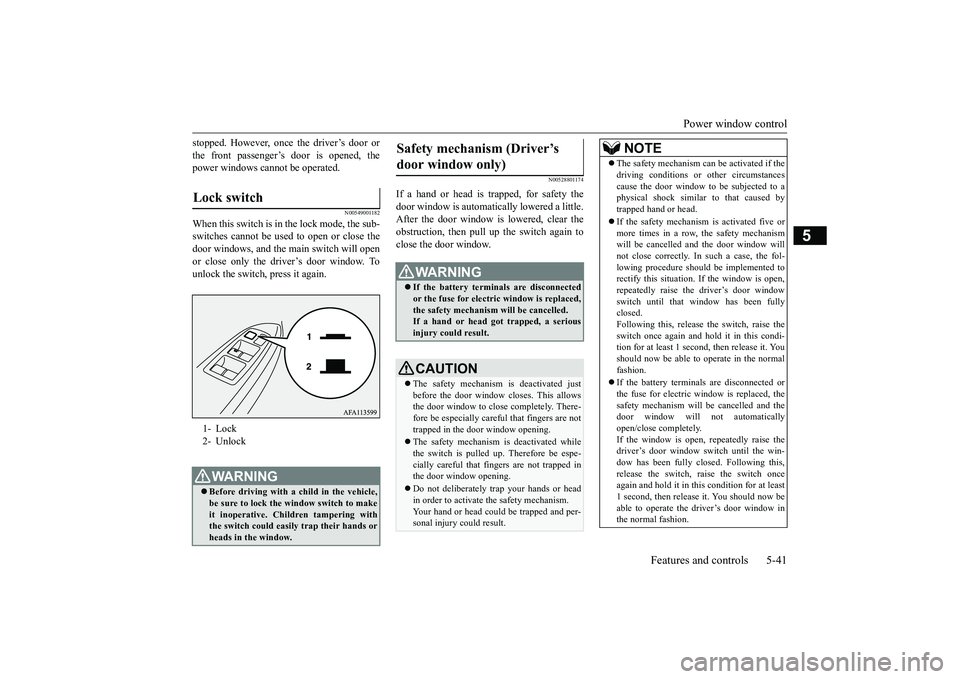
When this switch is in the lock mode, the sub-switches cannot be used to open or close the door windows, and the main switch will openor close only the driver’s door window. Tounlock the switch, press it again.
N00528801174
If a hand or head is trapped, for safety thedoor window is automatically lowered a little. After the door window is lowered, clear the obstruction, then pull up the switch again toclose the door window.
Lock switch 1- Lock 2- UnlockWA R N I N G Before driving with a child in the vehicle, be sure to lock the window switch to make it inoperative. Children tampering withthe switch could easily trap their hands or heads in the window.
Safety mechanism (Driver’s door window only)
WA R N I N G If the battery terminals are disconnected or the fuse for electric window is replaced, the safety mechanism will be cancelled.If a hand or head got trapped, a serious injury could result.CAUTION The safety mechanism is deactivated just before the door window closes. This allows the door window to close completely. There- fore be especially careful that fingers are nottrapped in the door window opening. The safety mechanism is deactivated while the switch is pulled up. Therefore be espe- cially careful that fingers are not trapped inthe door window opening. Do not deliberately trap your hands or head in order to activate the safety mechanism. Your hand or head could be trapped and per- sonal injury could result.
NOTE
The safety mechanism can be activated if the driving conditions or other circumstances cause the door window to be subjected to a physical shock similar to that caused by trapped hand or head. If the safety mechanism is activated five or more times in a row, the safety mechanismwill be cancelled and the door window will not close correctly. In such a case, the fol- lowing procedure should be implemented torectify this situation. If the window is open, repeatedly raise the driver’s door window switch until that window has been fullyclosed. Following this, release the switch, raise the switch once again and hold it in this condi-tion for at least 1 second,
then release it. You
should now be able to operate in the normal fashion. If the battery terminals are disconnected or the fuse for electric window is replaced, thesafety mechanism will be cancelled and the door window will not automatically open/close completely.If the window is open, repeatedly raise the driver’s door window switch until the win- dow has been fully closed. Following this, release the switch, raise the switch once again and hold it in this condition for at least1 second, then release it. You should now be able to operate the driver’s door window in the normal fashion.
BK0266800US.bo
ok 41 ページ 2018年6月27日 水曜日 午後5時6分
Page 132 of 423
Steering wheel height and reach adjustment
Features and controls 5-49
5
Warning light (yellow) Warning display If there is a malfunction in the system, the warning light will come on. In addition, thewarning display appears on the informationscreen in the multi-information display.
Under normal conditions, the warning light only comes on when the ignition switch is turned to the “ON” position or the operation mode is put in ON and goes off a few secondslater.
N00511501241
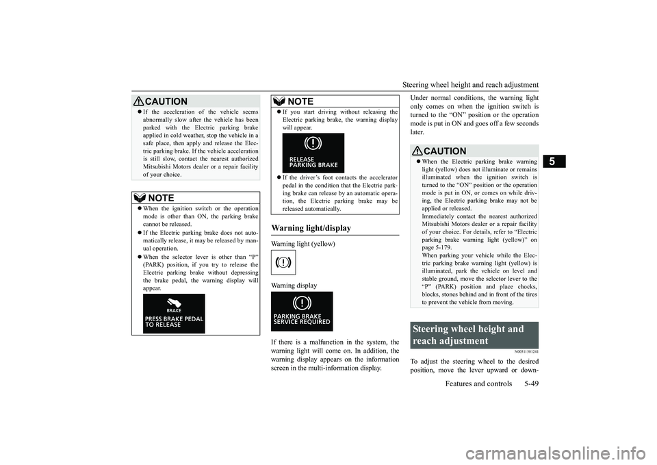
To adjust the steering wheel to the desiredposition, move the lever upward or down-
If the acceleration of the vehicle seems abnormally slow after the vehicle has been parked with the Electric parking brake applied in cold weather, stop the vehicle in a safe place, then apply and release the Elec-tric parking brake. If the vehicle acceleration is still slow, contact the nearest authorized Mitsubishi Motors dealer or a repair facilityof your choice.NOTE
When the ignition switch or the operation mode is other than ON, the parking brake cannot be released. If the Electric parking brake does not auto- matically release, it may be released by man-ual operation. When the selector lever is other than “P” (PARK) position, if you try to release the Electric parking brake without depressing the brake pedal, the warning display willappear.CAUTION
If you start driving without releasing the Electric parking brake, the warning display will appear. If the driver’s foot contacts the accelerator pedal in the condition that the Electric park-ing brake can release by an automatic opera- tion, the Electric parking brake may be released automatically.
Warning light/display
NOTE
CAUTION When the Electric parking brake warning light (yellow) does not illuminate or remains illuminated when the ignition switch isturned to the “ON” position or the operation mode is put in ON, or comes on while driv- ing, the Electric parking brake may not beapplied or released. Immediately contact the nearest authorized Mitsubishi Motors dealer or a repair facilityof your choice. For details, refer to “Electric parking brake warning light (yellow)” on page 5-179.When parking your vehicle while the Elec- tric parking brake warning light (yellow) is illuminated, park the vehicle on level andstable ground, move the selector lever to the “P” (PARK) position and place chocks, blocks, stones behind and in front of the tiresto prevent the vehicle from moving.
Steering wheel height and reach adjustment
BK0266800US.bo
ok 49 ページ 2018年6月27日 水曜日 午後5時6分
Page 133 of 423
Inside rearview mirror 5-50 Features and controls
5
ward while moving the steering wheel to the desired position.
N00511601415
Adjust the inside rear
view mirror only after
making any seat adjustme
nts so as to have a
clear view to the rear of the vehicle.
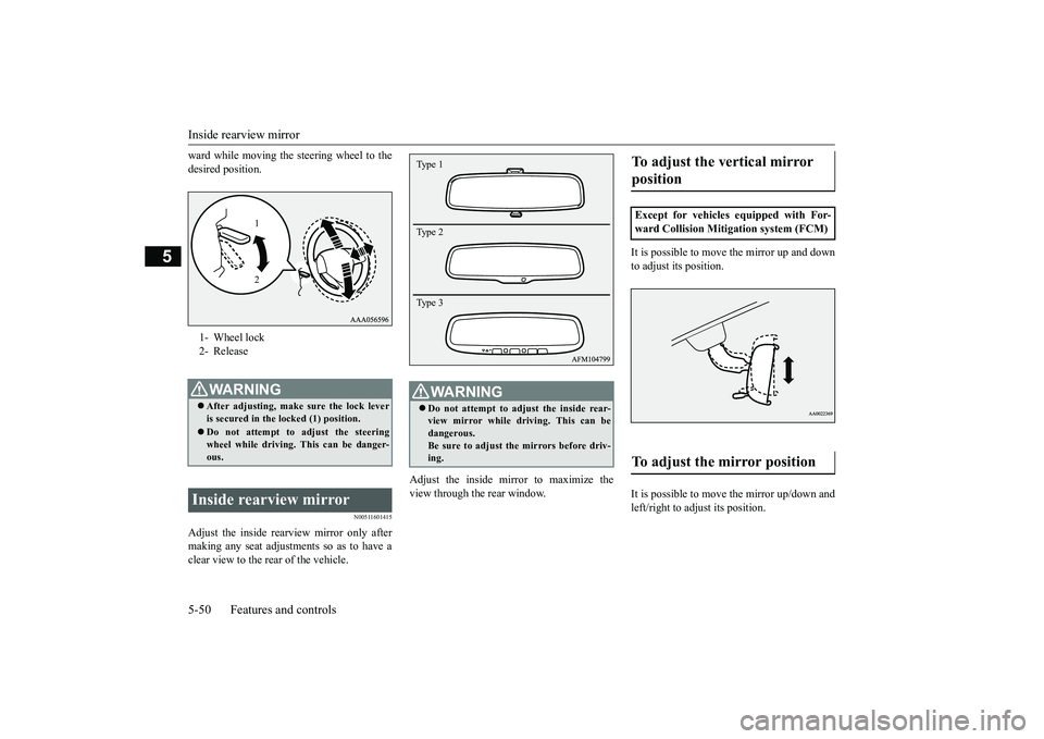
Adjust the inside mirror to maximize the view through the rear window.
It is possible to move
the mirror up and down
to adjust its position. It is possible to move the mirror up/down and left/right to adjust its position.
1- Wheel lock 2- ReleaseWA R N I N G After adjusting, make sure the lock lever is secured in the locked (1) position. Do not attempt to adjust the steering wheel while driving. This can be danger- ous.
Inside rearview mirror
1 2
WA R N I N G Do not attempt to adjust the inside rear- view mirror while driving. This can be dangerous. Be sure to adjust the mirrors before driv-ing.Type 1 Type 2 Type 3
To adjust the vertical mirror position Except for vehicles equipped with For- ward Collision Mitigation system (FCM)To adjust the mirror position
BK0266800US.bo
ok 50 ページ 2018年6月27日 水曜日 午後5時6分
Page 136 of 423
Outside rearview mirrors
Features and controls 5-53
5
N00549101196
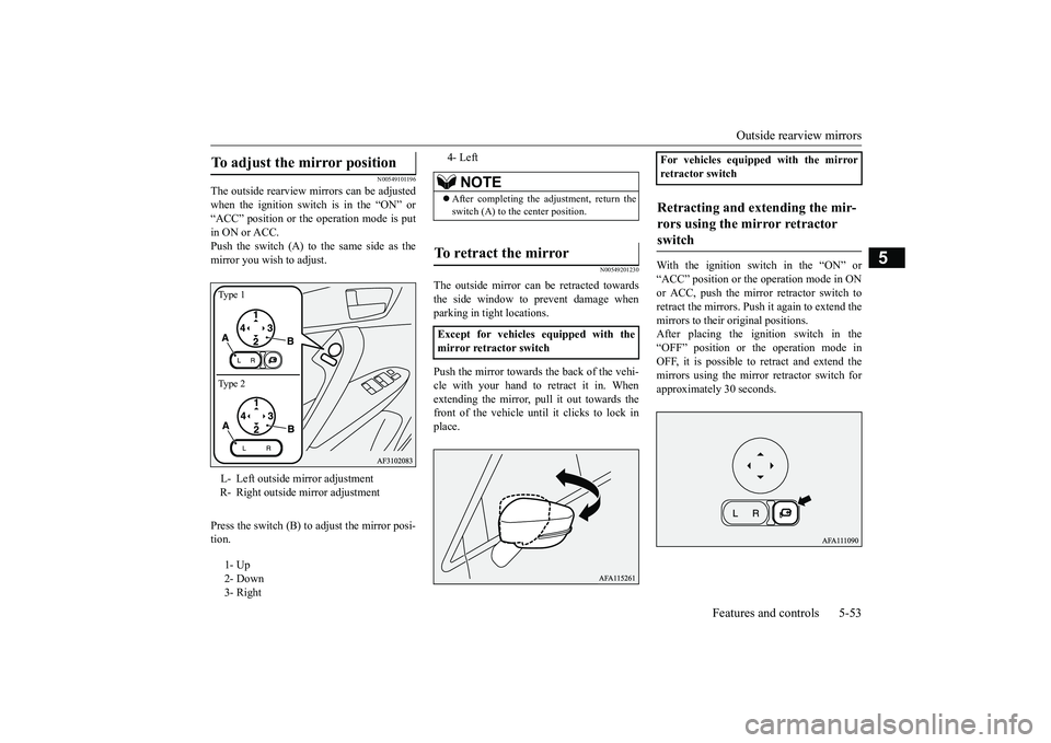
The outside rearview mirrors can be adjusted when the ignition switch is in the “ON” or“ACC” position or the operation mode is put in ON or ACC. Push the switch (A) to the same side as themirror you wish to adjust. Press the switch (B) to adjust the mirror posi- tion.
N00549201230
The outside mirror can be retracted towards the side window to prevent damage whenparking in tight locations. Push the mirror towards the back of the vehi- cle with your hand to retract it in. Whenextending the mirror, pull it out towards the front of the vehicle until it clicks to lock in place.
With the ignition switch in the “ON” or “ACC” position or the
operation mode in ON
or ACC, push the mirror retractor switch toretract the mirrors. Push it again to extend themirrors to their original positions. After placing the ignition switch in the “OFF” position or the operation mode inOFF, it is possible to retract and extend the mirrors using the mirror retractor switch for approximately 30 seconds.
To adjust the mirror position L- Left outside mirror adjustment R- Right outside mirror adjustment 1- Up 2- Down 3- RightType 1 Type 2
4- Left
NOTE
After completing the adjustment, return the switch (A) to the center position.
To retract the mirror Except for vehicles equipped with the mirror retractor switch
For vehicles equipped with the mirrorretractor switchRetracting and extending the mir- rors using the mirror retractor switch
BK0266800US.bo
ok 53 ページ 2018年6月27日 水曜日 午後5時6分
Page 137 of 423
![MITSUBISHI ECLIPSE CROSS 2019 (in English) Repair Manual Outside rearview mirrors 5-54 Features and controls
5
[For vehicles equipped with the keyless entry system]The mirrors automatically retract or extend when the doors are locked or unlocked using the k MITSUBISHI ECLIPSE CROSS 2019 (in English) Repair Manual Outside rearview mirrors 5-54 Features and controls
5
[For vehicles equipped with the keyless entry system]The mirrors automatically retract or extend when the doors are locked or unlocked using the k](/img/19/34870/w960_34870-136.png)
Outside rearview mirrors 5-54 Features and controls
5
[For vehicles equipped with the keyless entry system]The mirrors automatically retract or extend when the doors are locked or unlocked using the key of the keyless entry system.Refer to “Keyless entry system: Operation ofthe outside rearview mirrors” on page 5-6. [For vehicles equipped with the F.A.S.T.-key] The mirrors automatically retract or extendwhen the doors are locked or unlocked using the key or the F.A.S.T.-key. Refer to “Keyless entry system” on page 5-27or “To operate using the F.A.S.T.-key” on page 5-14.
N00595900022
CAUTION It is possible to retract and extend the mirrors by hand. After retracting a mirror using the mirror retractor switch, however, you should extend it by using the switch again, not by hand. If you extended the mirror by handafter retracting it using the switch, it would not properly lock in position. As a result, the mirror could move because of the wind orvibration while you are driving, and this may impair the driver’s rearward visibility.NOTE
Be careful not to get your hands trapped while a mirror is moving. If you move a mirror by hand or it moves after hitting a person or object, you may not be able to return it to its original position using the mirror retractor switch. If this hap-pens, push the mirror retractor switch to place the mirror in its retracted position and then push the switch again to return the mir-ror to its original position. When freezing has occurred and mirrors fail to operate as intended, please refrain from repeated pushing of the retractor switch as this action can result in burn-out of the mir- ror motor circuits.
Retracting and extending the mir- rors without using the mirror retractor switch (automatic exten- sion function)
NOTE
Functions can be modified as stated below. Please consult an authorized MitsubishiMotors dealer. On vehicles equipped with the Smartphone Link Display Audio, screen operations can be used to make the adjustment. Refer to the separate owner’s manual for details.
• Automatically extend when the ignition switch is turned to the “ON” position or the operation mode is put in ON with the driver’s door closed, and automatically retract when the ignition switch is turned tothe “OFF” or “ACC” position or the opera- tion mode is put in OFF or ACC with the driver’s door opened. • Automatically extend when the vehicle speed reaches approximately 19 mph(30 km/h). • Deactivate the automatic extension func- tion.
Integrated Blind Spot Mirrors
(if so equipped)
WA R N I N G Even if no vehicles are shown to the side of your vehicle in the Integrated Blind Spot Mirrors (A), be sure to confirm that traf-fic is clear before changing lanes. Because the Integrated Blind Spot Mir- rors (A) are wide-angle mirrors, objects appear smaller than their actual size.Also, be careful because vehicles and other objects shown in the mirrors are closer to your vehicle than they appear.NOTE
BK0266800US.bo
ok 54 ページ 2018年6月27日 水曜日 午後5時6分
Page 142 of 423
Turbocharger operation
Features and controls 5-59
5
lever in the “D” (DRIVE) or “R” (REVERSE) position. This occurs because the transaxle has not warmed up sufficiently; it does not indicate aproblem. If this occurs, place the selector lever in the “P” (PARK) position and let the engine idle for at least 10 minutes.The transaxle will warm up, and you will be able to start normally. Do not leave the vehicle during warm-upoperation.
N00537301090
N00560201073
The CVT will automatically and continuously change its gear ratio depending on road anddriving conditions. This helps achieve smooth driving and excellent fuel efficiency. If your vehicle is equipped with the spor-tronic steering wheel paddle shifter, you can manually shift the transmission up and down. Refer to “Sports mode” on page 5-63. The transmission prevents unnecessary upshifts even when the accelerator pedal is released and ensures smooth driving. According to the condi
tions, the transmission
will automatically shift to a lower gear ratioto achieve stronger engine braking. This may help reduce your need to use the service brake.
N00560301104
As an additional safe
ty precaution, models
equipped with a CVT have a shift-lock devicethat holds the selector lever in the “P” (PARK) position. To move the selector lever from the “P” (PARK) position to anotherposition, follow the steps below. 1. Press and hold the brake pedal down. 2. Press and hold the lock button. 3. Move the selector lever to the desired position.
The CVT selects an optimum ratio automati- cally when the selector lever is in the “D” (DRIVE) position, depending on the speed of the vehicle and the position of the acceleratorpedal. The selector lever (A) has two gates; the main gate (B) and sports mode gate (C).
Turbocharger operation
CAUTION Do not run the engine at high speeds (for example, by revving it or by acceleratingrapidly) immediately after starting it. Do not stop the engine immediately after high-speed or uphill driving. First allow the engine to idle to give the turbocharger a chance to cool down. Replace the engine oil at the specified inter- vals. If the engine oil is not replaced, the tur-bocharger could malfunction.
Continuously variable transmission (CVT) DRIVING UPHILL DRIVING DOWNHILL
Selector lever operation
NOTE
The selector lever cannot be moved from “P” (PARK) to other position if the ignitionswitch is set to the “OFF” or “ACC” posi- tion, or if the key has been removed, or the operation mode is put in OFF or ACC, or ifthe brake pedal is not
pressed and held down.
BK0266800US.bo
ok 59 ページ 2018年6月27日 水曜日 午後5時6分
Page 143 of 423
Continuously variable transmission (CVT) 5-60 Features and controls
5
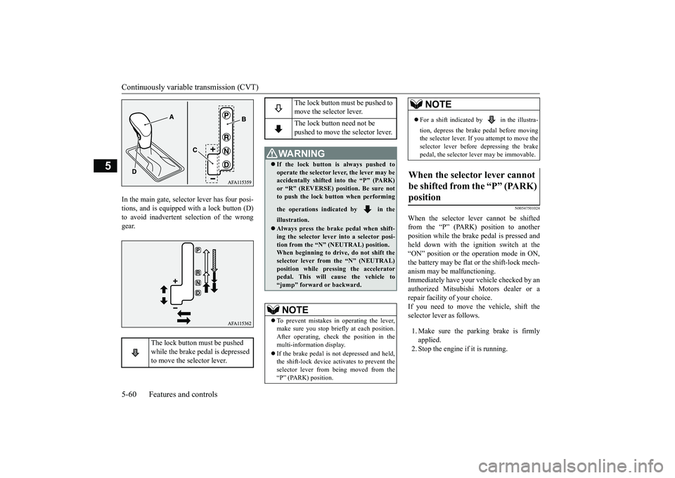
In the main gate, selector lever has four posi- tions, and is equipped with a lock button (D)to avoid inadvertent selection of the wrong gear.
N00547501024
When the selector lever cannot be shiftedfrom the “P” (PARK) position to another position while the brake pedal is pressed andheld down with the ignition switch at the“ON” position or the operation mode in ON, the battery may be flat or the shift-lock mech- anism may be malfunctioning.Immediately have your vehicle checked by an authorized Mitsubishi Motors dealer or a repair facility of your choice.If you need to move the vehicle, shift the selector lever as follows. 1. Make sure the parking brake is firmly applied.2. Stop the engine if it is running.
The lock button must be pushed while the brake pedal is depressed to move the selector lever.
The lock button must be pushed to move the selector lever. The lock button need not be pushed to move the selector lever.
WA R N I N G If the lock button is always pushed to operate the selector lever, the lever may be accidentally shifted into the “P” (PARK)or “R” (REVERSE) position. Be sure not to push the lock button when performing the operations indicated by in the illustration. Always press the brake pedal when shift- ing the selector lever into a selector posi- tion from the “N” (NEUTRAL) position.When beginning to driv
e, do not shift the
selector lever from the “N” (NEUTRAL) position while pressing the acceleratorpedal. This will cause the vehicle to “jump” forward or backward.NOTE
To prevent mistakes in operating the lever, make sure you stop briefly at each position. After operating, check the position in the multi-information display. If the brake pedal is not depressed and held, the shift-lock device activates to prevent theselector lever from being moved from the “P” (PARK) position.
For a shift indicated by in the illustra- tion, depress the brake pedal before moving the selector lever. If
you attempt to move the
selector lever before depressing the brake pedal, the selector lever may be immovable.
When the selector lever cannot be shifted from the “P” (PARK) position
NOTE
BK0266800US.bo
ok 60 ページ 2018年6月27日 水曜日 午後5時6分
Page 144 of 423
Continuously variable transmission (CVT)
Features and controls 5-61
5
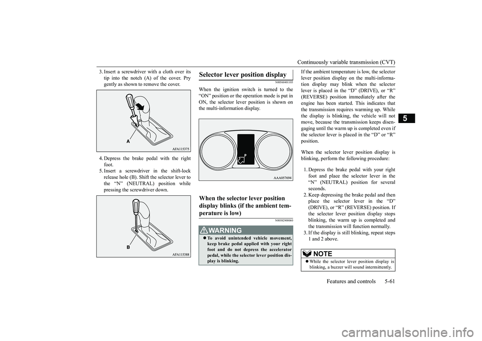
3. Insert a screwdriver with a cloth over its tip into the notch (A) of the cover. Pry gently as shown to remove the cover. 4. Depress the brake pedal with the right foot. 5. Insert a screwdriver in the shift-lockrelease hole (B). Shift the selector lever to the “N” (NEUTRAL) position while pressing the screwdriver down.
N00560401105
When the ignition switch is turned to the“ON” position or the operation mode is put inON, the selector lever position is shown on the multi-information display.
N00582900060
If the ambient temperature is low, the selector lever position display on the multi-informa- tion display may blink when the selector lever is placed in the “D” (DRIVE), or “R”(REVERSE) position immediately after the engine has been started. This indicates that the transmission requires warming up. Whilethe display is blinking, the vehicle will not move, because the transmission keeps disen- gaging until the warm up is completed even ifthe selector lever is placed in the “D” or “R”position. When the selector lever position display is blinking, perform the following procedure: 1. Depress the brake pedal with your right foot and place the selector lever in the“N” (NEUTRAL) position for several seconds. 2. Keep depressing the brake pedal and thenplace the selector lever in the “D” (DRIVE), or “R” (R
EVERSE) position. If
the selector lever position display stopsblinking, the warm up is completed and the transmission will function normally. 3. If the display is sti
ll blinking, repeat steps
1 and 2 above.
Selector lever position display When the selector lever position display blinks (if the ambient tem-perature is low)
WA R N I N G To avoid unintended vehicle movement, keep brake pedal applied with your right foot and do not depress the accelerator pedal, while the selector lever position dis-play is blinking.
NOTE
While the selector lever position display is blinking, a buzzer will sound intermittently.
BK0266800US.bo
ok 61 ページ 2018年6月27日 水曜日 午後5時6分
Page 145 of 423
Continuously variable transmission (CVT) 5-62 Features and controls
5
N00560501148
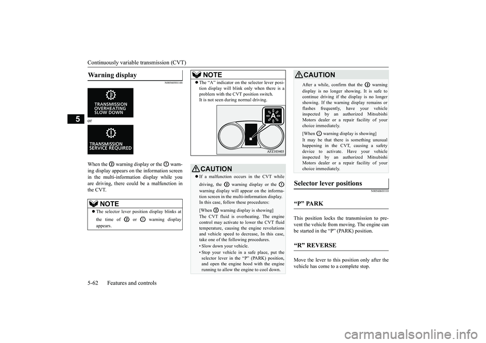
or When the warning display or the warn- ing display appears on the information screen in the multi-information display while you are driving, there could be a malfunction inthe CVT.
N00560601110
This position locks the transmission to pre-vent the vehicle from moving. The engine canbe started in the “P” (PARK) position. Move the lever to this position only after the vehicle has come to a complete stop.
Warning display
NOTE
The selector lever position display blinks at the time of or warning display appears.
The “A” indicator on the selector lever posi- tion display will blink only when there is a problem with the CVT position switch. It is not seen during normal driving.CAUTION If a malfunction occurs in the CVT while driving, the warning display or the warning display will appear on the informa- tion screen in the multi-information display. In this case, follow these procedures: [When warning display is showing] The CVT fluid is overheating. The engine control may activate to lower the CVT fluid temperature, causing the engine revolutions and vehicle speed to decrease, In this case, take one of the following procedures.• Slow down your vehicle.• Stop your vehicle in a safe place, put the selector lever in the “P” (PARK) position, and open the engine hood with the enginerunning to allow the engine to cool down.NOTE
After a while, confirm that the warning display is no longer showing. It is safe to continue driving if the display is no longer showing. If the warning display remains orflashes frequently, have your vehicle inspected by an authorized Mitsubishi Motors dealer or a repair facility of yourchoice immediately. [When warning display is showing] It may be that there is something unusual happening in the CVT, causing a safety device to activate. Have your vehicleinspected by an authorized Mitsubishi Motors dealer or a repair facility of your choice immediately.
Selector lever positions “P” PARK “R” REVERSE
CAUTION
BK0266800US.bo
ok 62 ページ 2018年6月27日 水曜日 午後5時6分