steering wheel MITSUBISHI ECLIPSE CROSS 2020 (in English) User Guide
[x] Cancel search | Manufacturer: MITSUBISHI, Model Year: 2020, Model line: ECLIPSE CROSS, Model: MITSUBISHI ECLIPSE CROSS 2020Pages: 427, PDF Size: 78.05 MB
Page 80 of 427
![MITSUBISHI ECLIPSE CROSS 2020 (in English) User Guide Supplemental Restraint System (SRS) - airbag
Seat and restraint systems 4-45
4
• Steering wheel • Instrument panel[For vehicles sold in U.S.A.] To contact Mitsubishi Motors North America, Inc.cal MITSUBISHI ECLIPSE CROSS 2020 (in English) User Guide Supplemental Restraint System (SRS) - airbag
Seat and restraint systems 4-45
4
• Steering wheel • Instrument panel[For vehicles sold in U.S.A.] To contact Mitsubishi Motors North America, Inc.cal](/img/19/34871/w960_34871-79.png)
Supplemental Restraint System (SRS) - airbag
Seat and restraint systems 4-45
4
• Steering wheel • Instrument panel[For vehicles sold in U.S.A.] To contact Mitsubishi Motors North America, Inc.call 1-888-648-7820 or write to: Mitsubishi Motors North America, Inc. Customer Relations DepartmentP.O. Box 6400Cypress, CA 90630-0064 [For vehicles sold in Canada] To contact Mitsubishi Motor Sales of Canada, Inc. call 1-888-576-4878 or write to:Mitsubishi Motor Sales of Canada, Inc. Customer Relations Department P.O. Box 410094141 Dixie Road Mississauga, ON L4W 5C9NOTE
[For vehicles sold in Puerto Rico] To contact Mitsubishi Motor Sales of Caribbean, Inc. call 1-787-251-8715 or write to:Mitsubishi Motor Sales of Caribbean, Inc. Customer Service DepartmentP.O. Box 192216 SAN JUAN PR 00919-2216 [For vehicles sold in Guam] To contact Triple J Enterprises Inc. call (671) 649-3673 or write to: Triple J Enterprises, Inc.P.O. Box 6066 TAMUNING GUAM 96931 [For vehicles sold in Saipan] To contact Triple J Motorscall (670) 234-7133 or write to: Triple J Motors P.O. Box 500487SAIPAN, MP96950-0487
[For vehicles sold in American Samoa] To contact Pacific Marketing Inc. call 684 (699) 9140 or write to: Pacific Marketing, Inc.P.O. Box 698 PAGO PAGO, AMERICAN SAMOA AS, 96799
BK0277700US.bo
ok 45 ページ 2019年3月8日 金曜日 午前9時23分
Page 134 of 427

Steering wheel height and reach adjustment
Features and controls 5-53
5
Warning light Warning display If there is a malfunction in the system, the warning light will come on. In addition, thewarning display appears on the information screen in the multi-information display.
Under normal conditions, the warning light only comes on when the ignition switch is turned to the “ON” position or the operation mode is put in ON and goes off a few secondslater.
N00511501241
To adjust the steering wheel to the desiredposition, move the lever upward or down-
If the acceleration of the vehicle seems abnormally slow after the vehicle has been parked with the Electric parking brake applied in cold weather, stop the vehicle in a safe place, then apply and release the Elec-tric parking brake. If the vehicle acceleration is still slow, contact the nearest authorized Mitsubishi Motors dealer or a repair facilityof your choice.NOTE
When the ignition switch or the operation mode is other than ON, the parking brake cannot be released. If the Electric parking brake does not auto- matically release, it may be released by man-ual operation. When the selector lever is other than “P” (PARK) position, if you try to release the Electric parking brake without depressing the brake pedal, the warning display willappear.CAUTION
If you start driving without releasing the Electric parking brake, the warning display will appear. If the driver’s foot contacts the accelerator pedal in the condition that the Electric park-ing brake can release by an automatic opera- tion, the Electric parking brake may be released automatically.
Warning light/display
NOTE
CAUTION When the Electric parking brake warning light does not illuminate or remains illumi- nated when the ignition switch is turned tothe “ON” position or the operation mode is put in ON, or comes on while driving, the Electric parking brake may not be applied orreleased. Immediately contact the nearest authorized Mitsubishi Motors dealer or a repair facilityof your choice. For details, refer to “Electric parking brake warning light” on page 5-184. When parking your vehicle while the Elec-tric parking brake warning light is illumi- nated, park the vehicle on level and stable ground, move the selector lever to the “P”(PARK) position and place chocks, blocks, stones behind and in front of the tires to pre- vent the vehicle from moving.
Steering wheel height and reach adjustment
BK0277700US.bo
ok 53 ページ 2019年3月8日 金曜日 午前9時23分
Page 135 of 427
Inside rearview mirror 5-54 Features and controls
5
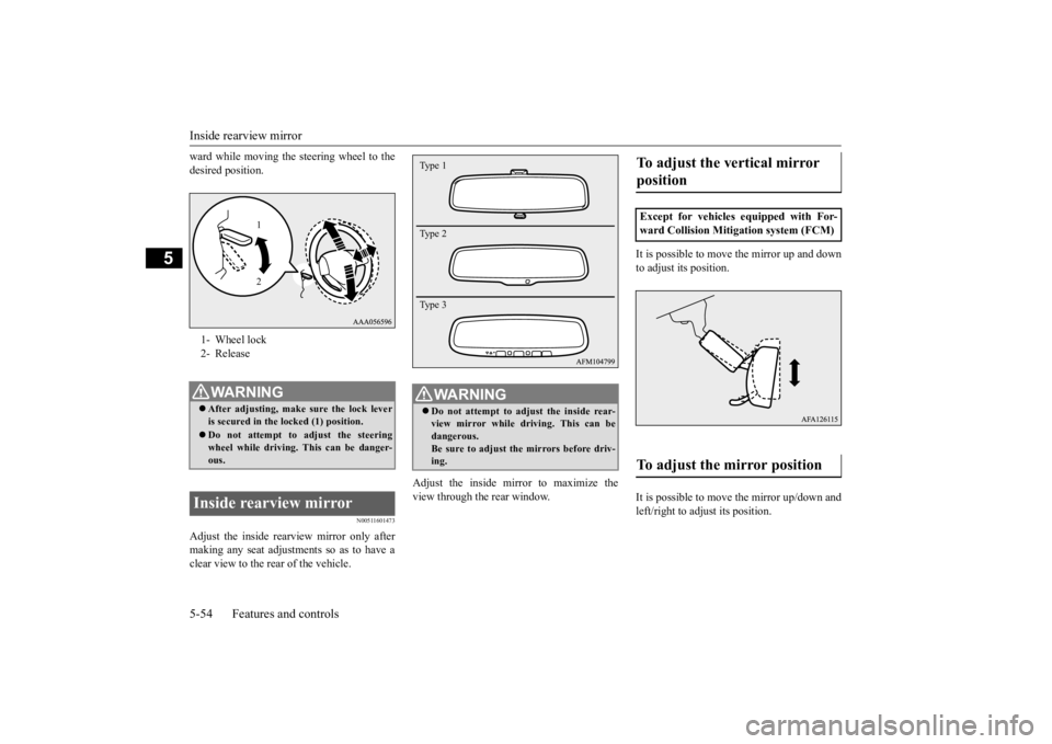
ward while moving the steering wheel to the desired position.
N00511601473
Adjust the inside rear
view mirror only after
making any seat adjustme
nts so as to have a
clear view to the rear of the vehicle.
Adjust the inside mirror to maximize the view through the rear window.
It is possible to move
the mirror up and down
to adjust its position. It is possible to move the mirror up/down and left/right to adjust its position.
1- Wheel lock 2- ReleaseWA R N I N G After adjusting, make sure the lock lever is secured in the locked (1) position. Do not attempt to adjust the steering wheel while driving. This can be danger- ous.
Inside rearview mirror
1 2
WA R N I N G Do not attempt to adjust the inside rear- view mirror while driving. This can be dangerous. Be sure to adjust the mirrors before driv-ing.Type 1 Type 2 Type 3
To adjust the vertical mirror position Except for vehicles equipped with For- ward Collision Mitigation system (FCM)To adjust the mirror position
BK0277700US.bo
ok 54 ページ 2019年3月8日 金曜日 午前9時23分
Page 148 of 427
Continuously variable transmission (CVT)
Features and controls 5-67
5
At this position, the transmission is disen- gaged. It is the same as the neutral position ona manual transaxle and
should be used when
the vehicle is not moving for an extended length of time during driving, such as in atraffic jam.
This position is used for most city and high- way driving. The transmission will automati-cally and continuously change its gear ratio depending on road and driving conditions.
N00560701124
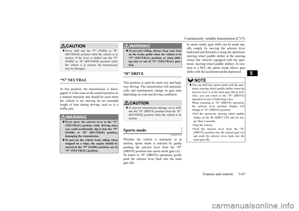
Whether the vehicle is stationary or inmotion, sports mode is selected by gently pushing the selector lever from the “D”(DRIVE) position into sports mode gate (A). To return to “D” (DRIVE) operation, gently push the selector lever back into the maingate (B).
In sports mode, gear shifts can be made rap- idly simply by moving the selector lever backward and forward or using the sportronic steering wheel paddle sh
ifter at the steering
wheel (for vehicles equipped with the spor- tronic steering wheel paddle shifter). In con- trast to a M/T, the sports mode allows gearshifts with the accelerator pedal depressed.
CAUTION Never shift into the “P” (PARK) or “R” (REVERSE) position while the vehicle is in motion. If the lever is shifted into the “P” (PARK) or “R” (REVERSE) position while the vehicle is in motion, the transmissionmay be damaged.
“N” NEUTRAL
WA R N I N G Never move the selector lever to the “N” (NEUTRAL) position while driving since you could accidentally slip it into the “P” (PARK) or “R” (REVERSE) position,damaging the transmission. To prevent the vehicle from rolling when stopped on a slope, the engine should be started in the “P” (PARK) position, not in“N” (NEUTRAL) position.
To prevent rolling, always keep your foot on the brake pedal when the vehicle is in “N” (NEUTRAL) position, or when shift- ing into or out of “N” (NEUTRAL) posi- tion.
“D” DRIVE
CAUTION To prevent transmission damage, never shift into the “D” (DRIVE) position from the “R”(REVERSE) position while the vehicle is in motion.
Sports mode
WA R N I N G
NOTE
You can shift into sports mode with the spor- tronic steering wheel paddle shifter when the selector lever is in the main gate (B) as well.Also, you can return to the “D” (DRIVE) operation in any of following ways. When returning to “D” (DRIVE) operation,the selector lever position display will change to “D” (DRIVE) position. • Pull the sportronic steering wheel paddle shifter on the (SHIFT UP) side for lon- ger than 2 seconds. • Stop the vehicle.• Push the selector lever from the “D” (DRIVE) position into the manual gate (A)and push the selector lever back into the main gate (B).
BK0277700US.bo
ok 67 ページ 2019年3月8日 金曜日 午前9時23分
Page 149 of 427
Continuously variable transmission (CVT) 5-68 Features and controls
5
N00560901083
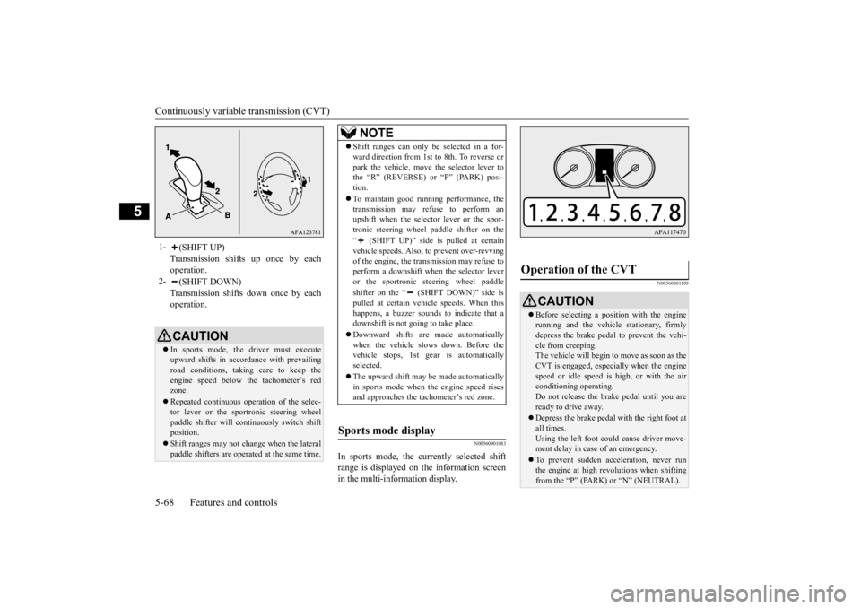
In sports mode, the currently selected shift range is displayed on the information screenin the multi-information display.
N00560801109
1-
(SHIFT UP) Transmission shifts up once by eachoperation.
2-
(SHIFT DOWN) Transmission shifts down once by eachoperation.CAUTION In sports mode, the
driver must execute
upward shifts in accordance with prevailing road conditions, taking care to keep the engine speed below the tachometer’s redzone. Repeated continuous operation of the selec- tor lever or the sportronic steering wheel paddle shifter will continuously switch shift position. Shift ranges may not change when the lateral paddle shifters are operated at the same time.
NOTE
Shift ranges can only be selected in a for- ward direction from 1st to 8th. To reverse or park the vehicle, move the selector lever to the “R” (REVERSE) or “P” (PARK) posi- tion. To maintain good running performance, the transmission may refuse to perform anupshift when the selector lever or the spor- tronic steering wheel paddle shifter on the “ (SHIFT UP)” side is pulled at certain vehicle speeds. Also, to prevent over-revving of the engine, the transmission may refuse toperform a downshift when the selector lever or the sportronic steering wheel paddle shifter on the “ (SHIFT DOWN)” side is pulled at certain vehicle speeds. When this happens, a buzzer sounds to indicate that a downshift is not going to take place. Downward shifts are made automatically when the vehicle slows down. Before the vehicle stops, 1st gear is automatically selected. The upward shift may be made automatically in sports mode when the engine speed risesand approaches the tachometer’s red zone.
Sports mode display
Operation of the CVT
CAUTION Before selecting a position with the engine running and the vehicle stationary, firmlydepress the brake pedal to prevent the vehi- cle from creeping. The vehicle will begin to move as soon as theCVT is engaged, especially when the engine speed or idle speed is high, or with the air conditioning operating.Do not release the brake pedal until you are ready to drive away. Depress the brake pedal
with the right foot at
all times. Using the left foot could cause driver move-ment delay in case of an emergency. To prevent sudden acceleration, never run the engine at high revolutions when shifting from the “P” (PARK) or “N” (NEUTRAL).
BK0277700US.bo
ok 68 ページ 2019年3月8日 金曜日 午前9時23分
Page 154 of 427
4-wheel drive operation
Features and controls 5-73
5
When turning a sharp corner in “GRAVEL” position at low speed, a slight difference in steering may be experienced similar to feel- ing as if the brakes were applied. This iscalled tight corner braking and results from each of the four tires being at a different dis- tance from the corner. The phenomenon istypical of 4-wheel drive vehicles. If this occurs, either straighten out the steering wheel or change to another mode. Set the drive mode-selector to “SNOW” in accordance with the road conditions, and thengradually depress the accelerator pedal for a smooth start.
Set the drive mode-selector to “GRAVEL” and then gradually depress the accelerator pedal for a smooth start. Keep the pressure onthe accelerator pedal as constant as possible, and drive at low speed.
NOTE
Driving on rough roads can be hard on a vehicle. Before you leave the pavement, be sure all scheduled maintenance and service has been done, and that you have inspected your vehicle. Pay special attention to thecondition of the tires, and check the tire pres- sures. Mitsubishi Motors is not responsible to the operator for any damage or injury caused or liability incurred by improper and negligentoperation of a vehicle. All techniques of vehicle operation depend on the skill and experience of the operator and other partici-pating parties. Any deviation from the rec- ommended operating instructions above is at their own risk. Note that the stopping distance required of the 4-wheel drive vehicle differs very littlefrom that of the front-wheel drive vehicle. When driving on a snow-covered road or a slippery, muddy surface, make sure that youkeep a sufficient distance between your vehi- cle and the one ahead of you. The driving posture should be more upright; adjust the seat to a good position for easy steering and pedal operation. Be sure to wearthe seat belt. After driving on rough roads, check each part of the vehicle and wash it thoroughly with water. Refer to the “Inspection andmaintenance following rough road opera- tion” section and “Vehicle care and Mainte- nance” sections.
CAUTION Setting the drive mode-selector to “GRAVEL” and “SNOW” position to drive on dry paved road will increase fuel con- sumption, with possible noise and vibration generation.
Turning sharp corners On snowy or icy roads
NOTE
The use of snow tires is recommended.
Maintain a safe distance between vehicles, avoid sudden braking, and use engine brak- ing (downshifting).CAUTION Avoid sudden braking, sudden acceleration and sharp turning. Skidding occurs and con- trol of the vehicle could be lost.
Driving on sandy or muddy roads
CAUTION Do not force the vehicle or drive recklessly on sandy surfaces. In comparison with nor- mal road surfaces, the engine and other drive-system components are put underexcessive strain when driving on such a sur- face. This could lead to accidents. If any of the following conditions occur while the vehicle is being driven, immedi- ately park your vehicle in a safe place andfollow these procedures:NOTE
BK0277700US.bo
ok 73 ページ 2019年3月8日 金曜日 午前9時23分
Page 159 of 427
Brake auto hold (if so equipped) 5-78 Features and controls
5
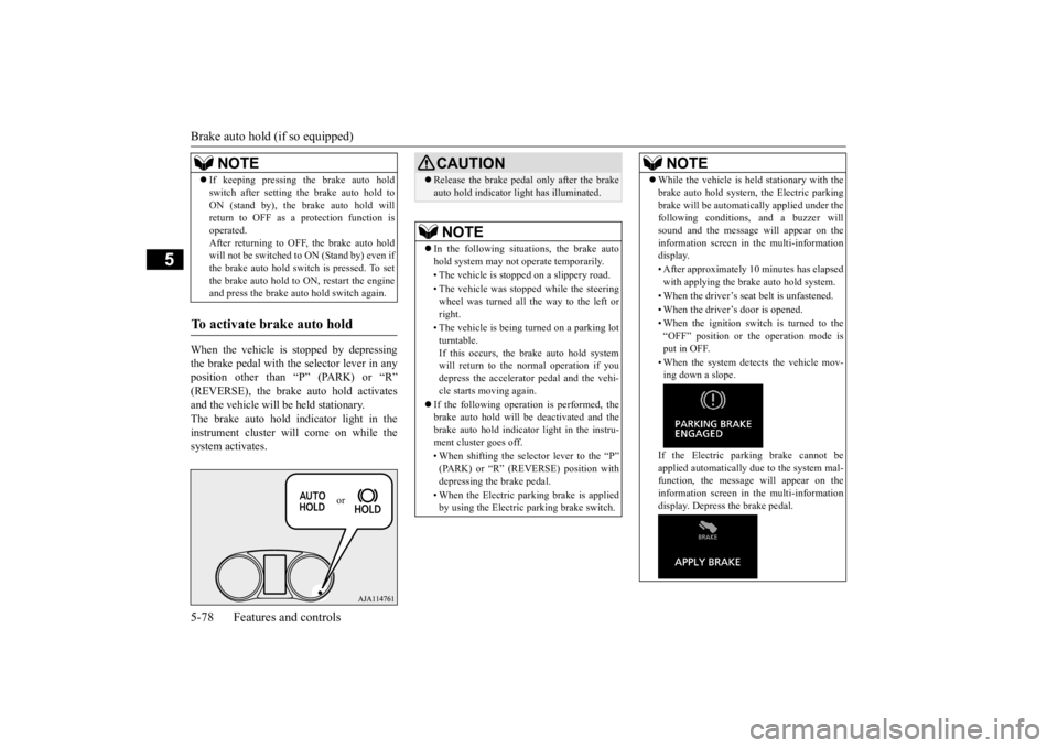
When the vehicle is stopped by depressing the brake pedal with the selector lever in anyposition other than “P” (PARK) or “R” (REVERSE), the brake auto hold activates and the vehicle will be held stationary.The brake auto hold indicator light in the instrument cluster will come on while the system activates. If keeping pressing the brake auto hold switch after setting the brake auto hold to ON (stand by), the brake auto hold will return to OFF as a protection function is operated.After returning to OFF, the brake auto hold will not be switched to ON (Stand by) even if the brake auto hold switch is pressed. To setthe brake auto hold to ON, restart the engine and press the brake auto
hold switch again.
To activate brake auto hold
NOTE
or
CAUTIONRelease the brake pedal only after the brake auto hold indicator light has illuminated.NOTE
In the following situations, the brake auto hold system may not operate temporarily. • The vehicle is stopped on a slippery road. • The vehicle was stopped while the steering wheel was turned all the way to the left or right. • The vehicle is being turned on a parking lot turntable. If this occurs, the brake auto hold systemwill return to the normal operation if you depress the accelerator pedal and the vehi- cle starts moving again.
If the following operation is performed, the brake auto hold will be deactivated and thebrake auto hold indicator light in the instru- ment cluster goes off. • When shifting the selector lever to the “P” (PARK) or “R” (REVERSE) position with depressing the brake pedal. • When the Electric parking brake is applied by using the Electric parking brake switch.
While the vehicle is held stationary with the brake auto hold system, the Electric parking brake will be automatically applied under the following conditions, and a buzzer will sound and the message will appear on theinformation screen in the multi-information display. • After approximately 10 minutes has elapsed with applying the brake auto hold system. • When the driver’s seat belt is unfastened. • When the driver’s door is opened.• When the ignition switch is turned to the “OFF” position or the operation mode isput in OFF. • When the system detects the vehicle mov- ing down a slope. If the Electric parking brake cannot be applied automatically due to the system mal-function, the message
will appear on the
information screen in the multi-information display. Depress the brake pedal.NOTE
BK0277700US.bo
ok 78 ページ 2019年3月8日 金曜日 午前9時23分
Page 161 of 427
Brake assist system 5-80 Features and controls
5
3. Depress the accelerator pedal and the hill start assist will gradually decrease the braking force as the vehicle starts moving.
N00562801129
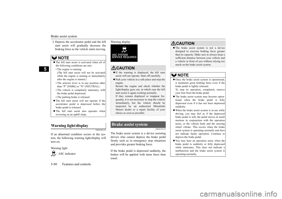
If an abnormal condition occurs in the sys- tem, the following warning light/display will turn on. Warning light
- ASC indicator
Warning display
N00567301145
The brake assist system is a device assisting drivers who cannot depress the brake pedal firmly such as in emergency stop situations and provides greater braking force. If the brake pedal is depressed suddenly, the brakes will be applied with more force thanusual.
NOTE
The hill start assist is activated when all of the following conditions are met. • The engine is running. (The hill start assist will not be activated while the engine is starting or immediately after the engine is started.) • The selector lever is in any position other than “P” (PARK) or “N” (NEUTRAL). • The vehicle is completely stationary, with the brake pedal depressed. • The parking brake is released. The hill start assist will not operate if the accelerator pedal is depressed before the brake pedal is released. The hill start assist also operates when reversing on an uphill slope.
Warning light/display
CAUTION If the warning is displayed, the hill start assist will not operate. Start off carefully. Park your vehicle in a safe place and stop the engine.Restart the engine and check whether the light/display goes out, in which case the hill start assist is again working normally. If they remain displayed or reappear fre- quently, it is not necessary to stop the vehicle immediately, but the vehicle should beinspected by an authorized Mitsubishi Motors dealer or a repair facility of your choice as soon as possible.
Brake assist system
CAUTION The brake assist system is not a device designed to exercise braking force greater than its capacity. Make sure to always keep a sufficient distance between your vehicle and a vehicle in front of you without relying toomuch on the brake assist system.NOTE
Once the brake assist system is operational, it maintains great braking force even if thebrake pedal is lightly released. To stop its operation, completely remove your foot from the brake pedal. The brake assist system may become opera- tional when the brake pedal is fullydepressed even if it has not been depressed suddenly. When the brake assist system is in use while driving, you may feel as if the depressed brake pedal is soft, the pedal moves in smallmotions in conjunction with the operation noise, or the vehicle body and the steering wheel vibrate. This occurs when the brakeassist system is operating normally and does not indicate faulty operation. Continue to depress the brake pedal. You may hear an operation noise when the brake pedal is suddenly or fully depressed while stationary. This does not indicate a malfunction and the brake assist system isoperating normally.
BK0277700US.bo
ok 80 ページ 2019年3月8日 金曜日 午前9時23分
Page 162 of 427
Active Yaw Control (AYC) Features and controls 5-81
5
N00596700027
The Active Yaw Control (AYC) is a system with a yaw control function, that controls the left-right driving/braking force using the brakes. The yaw control function is a function that enhances vehicle cornering performance andvehicle stability with management of vehicle turning power (yaw moment) by controlling the drive power difference of the left andright wheels and the braking force when the vehicle does not turn in response to steering input, such as when the steering wheel isturned quickly or when driving on slippery road.
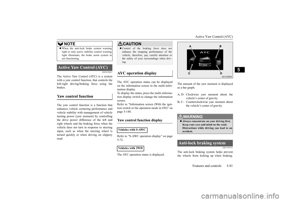
The AYC operation status can be displayed on the information screen in the multi-infor- mation display. To display the status, press the multi-informa-tion display switch to change the information screen. Refer to “Information screen (With the igni-tion switch or the operation mode in ON)” on page 5-148. Refer to “S-AWC operation display” on page 5-72. The AYC operation status is displayed.
The amount of the yaw moment is displayed as a bar graph.
N00517901351
The anti-lock braking system helps preventthe wheels from locking up when braking.
When the anti-lock brake system warning light or only active stability control warning light illuminate, the brake assist system in not functioning.
Active Yaw Control (AYC) Yaw control function
NOTE
CAUTION Control of the braking force does not enhance the stopping performance of the vehicle, therefore, pay careful attention to the safety of your surroundings when driv- ing.
AYC operation display Yaw control function display Vehicles with S-AWC Vehicles with 2WD
A, D- Clockwise yaw moment about the
vehicle’s center of gravity
B, C- Counterclockwise yaw moment about
the vehicle’s center of gravityWA R N I N G Always concentrate on your driving first. Keep your eyes and
mind on the road.
Distractions while driving can lead to anaccident.
Anti-lock braking system
BK0277700US.bo
ok 81 ページ 2019年3月8日 金曜日 午前9時23分
Page 163 of 427
Anti-lock braking system 5-82 Features and controls
5
This helps maintain vehicle drivability and steering wheel handling. When using the anti-lock brakes (sudden braking), steering is slightly differentfrom normal driving conditions. Use the steering wheel carefully. Always keep a safe distance from the vehicle in front of you. Even if your vehi-cle is equipped with the anti-lock braking system, leave a greater braking distance when:• Driving on gravel or snow-covered roads. • Driving on uneven road surfaces. Operation of anti-lock braking system is not restricted situations where brakes are applied suddenly. This system may alsoprevent the wheels from locking when you drive over manholes, steel roadwork plates, road markings, or any uneven roadsurface. When the anti-lock braking system is in use, you may feel the brake pedal vibrat-ing and hear a unique sound. It may also feel as if the pedal resists being pressed. In this situation, simply hold the brakepedal down firmly. Do not pump the brake, which will result in reduced braking performance.
N00531601701
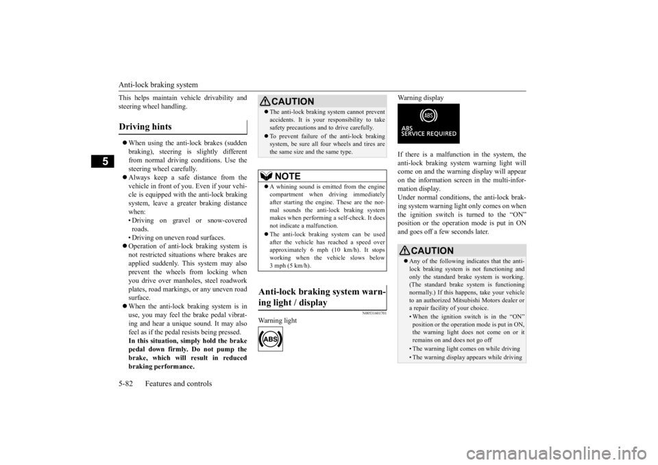
Warning light
Warning display If there is a malfunction in the system, the anti-lock braking system warning light will come on and the warning display will appearon the information screen in the multi-infor-mation display. Under normal conditions
, the anti-lock brak-
ing system warning light only comes on whenthe ignition switch is turned to the “ON” position or the operation mode is put in ON and goes off a few seconds later.
Driving hints
CAUTION The anti-lock braking system cannot prevent accidents. It is your responsibility to take safety precautions and to drive carefully. To prevent failure of the anti-lock braking system, be sure all four wheels and tires are the same size and the same type.NOTE
A whining sound is emitted from the engine compartment when driving immediately after starting the engine. These are the nor- mal sounds the anti-lock braking systemmakes when performing a self-check. It does not indicate a malfunction. The anti-lock braking system can be used after the vehicle has reached a speed over approximately 6 mph (10 km/h). It stopsworking when the vehicle slows below 3 mph (5 km/h).
Anti-lock braking system warn- ing light / display
CAUTION Any of the following indicates that the anti- lock braking system is not functioning and only the standard brake system is working.(The standard brake system is functioning normally.) If this happens, take your vehicle to an authorized Mitsubishi Motors dealer ora repair facility of your choice. • When the ignition switch is in the “ON” position or the operation mode is put in ON, the warning light does not come on or itremains on and does not go off• The warning light comes on while driving• The warning display appears while driving
BK0277700US.bo
ok 82 ページ 2019年3月8日 金曜日 午前9時23分