Head unit MITSUBISHI ECLIPSE CROSS 2020 Owner's Manual (in English)
[x] Cancel search | Manufacturer: MITSUBISHI, Model Year: 2020, Model line: ECLIPSE CROSS, Model: MITSUBISHI ECLIPSE CROSS 2020Pages: 427, PDF Size: 78.05 MB
Page 9 of 427
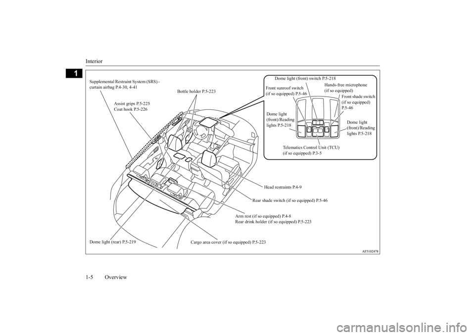
Interior 1-5 Overview
1
Assist grips P.5-225 Coat hook P.5-226
Bottle holder P.5-223
Head restraints P.4-9
Arm rest (if so equipped) P.4-8 Rear drink holder (if so equipped) P.5-223
Cargo area cover (if so equipped) P.5-223
Supplemental Restraint System (SRS) - curtain airbag P.4-30, 4-41 Dome light (rear) P.5-219
Front shade switch (if so equipped) P.5-46
Dome light (front) switch P.5-218
Front sunroof switch (if so equipped) P.5-46
Dome light (front)/Reading lights P.5-218
Hands-free microphone (if so equipped)
Dome light (front)/Reading lights P.5-218
Telematics Control Unit (TCU) (if so equipped) P.3-5
Rear shade switch (if
so equipped) P.5-46
BK0277700US.bo
ok 5 ページ 2019年3月8日 金曜日 午前9時23分
Page 16 of 427
If this warning light comes on or
flashes while you’re driving...
Quick index 2-3
2
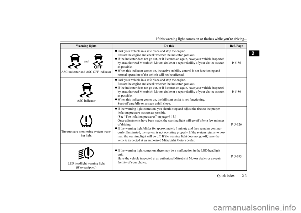
and
ASC indicator and ASC OFF indicator
Park your vehicle in a safe place and stop the engine. Restart the engine and check whether the indicator goes out. If the indicator does not go out, or if it
comes on again, have your vehicle inspected
by an authorized Mitsubishi Motors dealer or
a repair facility of your choice as soon
as possible. When this indicator comes on, the active
stability control is not functioning and
normal operation of the vehicle will not be affected.
P. 5-86
ASC indicator
Park your vehicle in a safe place and stop the engine. Restart the engine and check whether the indicator goes out. If the indicator does not go out, or if it
comes on again, have your vehicle inspected
by an authorized Mitsubishi Motors dealer or
a repair facility of your choice as soon
as possible. When this indicator comes on, the hi
ll start assist is not functioning.
Start off carefully on a steep uphill slope.
P. 5-80
Tire pressure monitoring system warn-
ing light
If the warning light comes on, you should stop and adjust the tires to the proper inflation pressure as soon as possible. (See “Tire inflation pressures” on page 9-15.)Once adjustments have been made, the warning light will go off after a few minutes of driving. If the warning light blinks for approxim
ately 1 minute and then remains continu-
ously illuminated, the system is not operatin
g properly. If the system returns to nor-
mal, the warning light will go off. If
the warning light does not go off, have the
vehicle inspected at an authori
zed Mitsubishi Motors dealer.
P. 5-126
LED headlight warning light
(if so equipped)
If the warning light comes on, there may be
a malfunction in the LED headlight
unit. Have the vehicle inspected at an authorized
Mitsubishi Motors dealer or a repair
facility of your choice.
P. 5-193
Wa r n i n g l i g h t s
Do this
Ref. Page
BK0277700US.bo
ok 3 ページ 2019年3月8日 金曜日 午前9時23分
Page 32 of 427
Telematics Control Unit (TCU) (if so equipped)
General information 3-11
3
Geofence If the specified area is set beforehand using the smartphone app, an alert is sent to the smartphone using a short messageservice (SMS), e-mail, or push notifica- tion when the vehicle enters or leaves that area. Curfew alert If the specified time of day is set before- hand using the smartphone app and theowner portal, an alert is sent to the smart-phone using a short message service (SMS), e-mail, or push notification when the curfew is violated. Vehicle settings You can change settings of items such as “Auto Fold Mirrors” and “HeadlightTimeout when Exiting Vehicle” from the smartphone app and the owner portal. Vehicle Status Report (VSR) The vehicle communication and informa- tion regarding malfunctions can be trans- mitted using the TCU so that thecondition of the vehicle can be checked using the smartphone app and the owner portal. Over The Air Update When software and firmware updates are available, notifications via SMS will besent to you to install the updates. You can also check for available updates manually.
Model name: LE920A4-NA Auto FCC ID: RI7LE920A4NAYour TCU operates on a radio frequency sub-ject to Federal Communications Commission (FCC) Rules (for vehicles sold in U.S.A.). This device complies with Part 15 of the FCCRules. Operation is subject to the following two conditions: This device may not cause harmful inter- ference. This device must accept any interference received, including interference that may cause undesired operation.
FCC Notice: This equipment has been tested and found to comply with the limits for a Class B digital device, pursuant to part 15 of
WA R N I N G Do not use the TCU if children, persons in need of care, pets, etc., are in the vehicle. Even if the remote climate control is used, the cabin may become too hot or cold if the system stops automatically or due tosome other reason. The cabin temperature may quickly rise in sunshine, which poses a risk of heat stroke and dehydration. Incold weather, on the other hand, the cabin temperature may quickly drop. Either of which could lead to death in the worstcase. In addition, children can activate switches and controls, resulting in an injury orfatal accident.CAUTION When using the remote climate control, do not use a car cover.NOTE
Air conditioning performance may deterio- rate under the following conditions: • In extremely hot weather • In hot sunshine • In extremely cold weather The remote climate control turns off auto- matically after approximately 10 minutes.The remote climate control can be operated up to two times consecutively.
Use the remote climate control according to the state or local regulations regarding idling vehicles.
General information
CAUTION Changes or modifications made to this equipment not expressly approved by themanufacturer may void the FCC authoriza- tion to operate this equipment.NOTE
BK0277700US.bo
ok 11 ページ 2019年3月8日 金曜日 午前9時23分
Page 65 of 427
Maintenance and inspection of seat belts 4-30 Seat and restraint systems
4
N00407001417
Regularly check your seat belt buckles and their release mechanisms for positive engage-ment and release of the latch plate. Check the retractors for automatic locking when in the Automatic Locking Retractor function. The entire seat belt assembly should be replaced if the webbing shows any obviouscuts, tears, increase in thickness in any sec- tion of the webbing from broken fibers, or severe fading from sunlight. All of these con-ditions indicate a weakening of the belt, which may adversely affect seat belt perfor- mance in an accident.
N00407701892
This vehicle is equipped with a SupplementalRestraint System (SRS), which includes air-bags for the driver and passengers. The SRS front airbags are designed to supple- ment the primary protection of the driver and front passenger seat belt systems by provid- ing those occupants with protection against
head and chest injuries in certain moderate to severe frontal collisions. The SRS front air- bags, together with sensors at the front of the vehicle and sensors attached to the frontseats, form an advanced airbag system. The SRS driver’s knee airbag is designed to supplement the primary protection of the driver’s seat belt system. It can reduce theforward movement of the driver’s lower legs and provide increased overall body protection in certain moderate to severe frontal colli-sions. The SRS side airbags and the curtain airbags are also designed to supplement the seat belts. The SRS side airbags provide the driver and front passenger with protection against chestinjuries by deploying the bag on the side impacted in moderate to severe side impact collisions. The SRS curtain airbags provide the driver and the passengers on the front seat and the rear outboard seats with protection against head injuries by deploying the curtain airbagon the side impacted in moderate to severe side impact collisions and by deploying both curtain airbags when a rollover is detected.The curtain airbags are also designed to help reduce the risk of complete and partial ejec- tion from the vehicle through side windows
Maintenance and inspection of seat belts
WA R N I N G Do not attempt to repair or replace any part of the seat belt assemblies. This work should be done by an authorizedMitsubishi Motors dealer. Failure to have an authorized Mitsubishi Motors dealer perform the work could reduce the effec- tiveness of the belts and could result in a serious injury or death in an accident.
Never use an organic solvent to clean the seat belt webbing. Do not attempt to bleach or re-dye the seat belt webbing. These may weaken the seat belt webbing, increasing risk of injury or death in anaccident. Clean seat belt webbing only with mild soap or detergent solution and rinse itwith lukewarm water, and dry the seat belt webbing completely before retracting it.
Supplemental Restraint Sys- tem (SRS) - airbag
NOTE
The SOS emergency assistance (if so equipped) is designed to operate when any of the airbags deploy or severe collision occurs. Refer to “Telematics Control Unit (TCU)” on page 3-5.WA R N I N G
BK0277700US.bo
ok 30 ページ 2019年3月8日 金曜日 午前9時23分
Page 240 of 427
Multi-information display
Features and controls 5-159
5
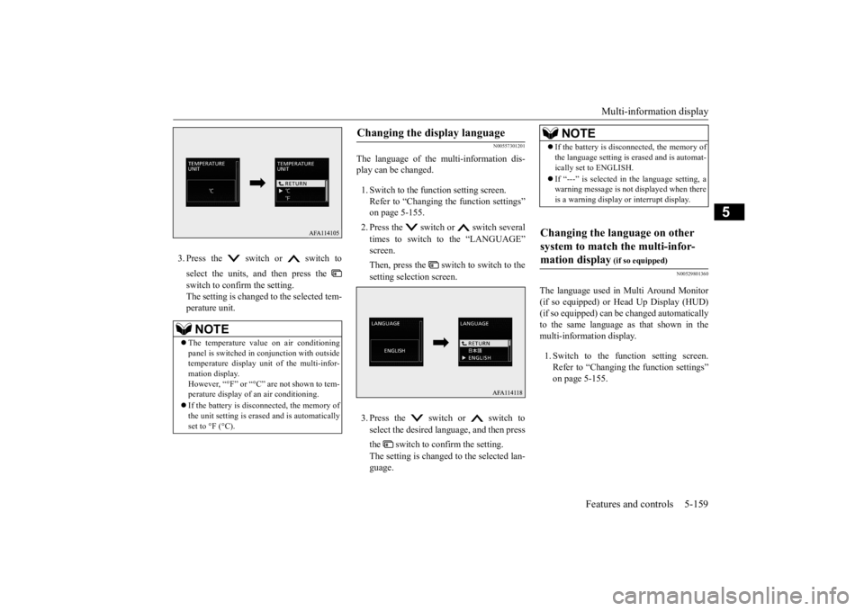
3. Press the switch or switch to select the units, and then press the switch to confirm the setting. The setting is changed to the selected tem-perature unit.
N00557301201
The language of the multi-information dis-play can be changed. 1. Switch to the function setting screen. Refer to “Changing the function settings” on page 5-155. 2. Press the switch or switch several times to switch to the “LANGUAGE” screen. Then, press the switch to switch to the setting selection screen. 3. Press the switch or switch to select the desired language, and then press the switch to confirm the setting. The setting is changed to the selected lan- guage.
N00529801360
The language used in Multi Around Monitor (if so equipped) or Head Up Display (HUD) (if so equipped) can be changed automatically to the same language as that shown in themulti-information display. 1. Switch to the function setting screen. Refer to “Changing the function settings” on page 5-155.
NOTE
The temperature value on air conditioning panel is switched in conjunction with outside temperature display unit of the multi-infor-mation display. However, “°F” or “°C” are not shown to tem- perature display of an air conditioning. If the battery is disconnected, the memory of the unit setting is erased and is automaticallyset to °F (°C).
Changing the display language
NOTE
If the battery is disconnected, the memory of the language setting is erased and is automat- ically set to ENGLISH. If “---” is selected in the language setting, a warning message is not displayed when there is a warning display or interrupt display.
Changing the language on other system to match the multi-infor- mation display
(if so equipped)
BK0277700US.book
159 ページ 2019年3月8日 金曜日 午前9時23分
Page 274 of 427
Combination headlights and dimmer switch
Features and controls 5-193
5
N00532601652
If the following operation is performed with the combination headlights and dim- mer switch in the “ ” or “ ” position, the lights automatically turn off. [Except for vehicles equipped with the F. A . S . T. - k e y ] The ignition switch is
turned to the “OFF”
or “ACC” position or the key is removed from the ignition switch and the driver’s door is opened. [For vehicles equipped with the F.A.S.T.- key] The operation mode is changed to OFF or ACC and the driver’s door is opened. If the following operation is performed with the combination headlights and dim- mer switch in the “ ” or “ ” position, the lights automatically turn off after approximately 3 minutes. [Except for vehicles equipped with the F. A . S . T. - k e y ] The ignition switch is
turned to the “OFF”
or “ACC” position or the key is removedfrom the ignition switch and the driver’sdoor is not opened.
[For vehicles equipped with the F.A.S.T.- key] The operation mode is changed to OFF or ACC and the driver’s door is not opened.
If the combination headlights and dimmer switch is turned to the “ ” or “ ” posi- tion again after the engine is turned off, theapproximately 3-minute auto-cutout function described above will not work. The lights (the parking lights, tail lights and license platelights) will stay on and will not turn off auto- matically.
N00584500044
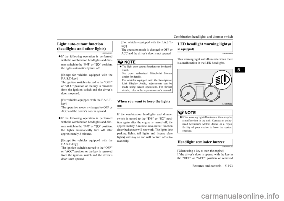
This warning light will
illuminate when there
is a malfunction in the LED headlights.
N00549801252
[When using a key to start the engine]If the driver’s door is opened with the key in the “OFF” or “ACC” position or removed
Light auto-cutout function (headlights and other lights)
NOTE
The light auto-cutout function can be deacti- vated.See your authorized Mitsubishi Motors dealer for details. For vehicles equipped with the SmartphoneLink Display Audio, adjustments can be made using screen operations. For further details, refer to the separate owner’s manual.
When you want to keep the lights on:
LED headlight warning light
(if
so equipped)
NOTE
If the warning light illuminates, there may be a malfunction in the unit. Contact an autho- rized Mitsubishi Motors dealer or a repairfacility of your choice to have the system checked.
Headlight reminder buzzer
BK0277700US.book
193 ページ 2019年3月8日 金曜日 午前9時23分
Page 295 of 427
HomeLink® Wireless Control System (if so equipped) 5-214 Features and controls
5
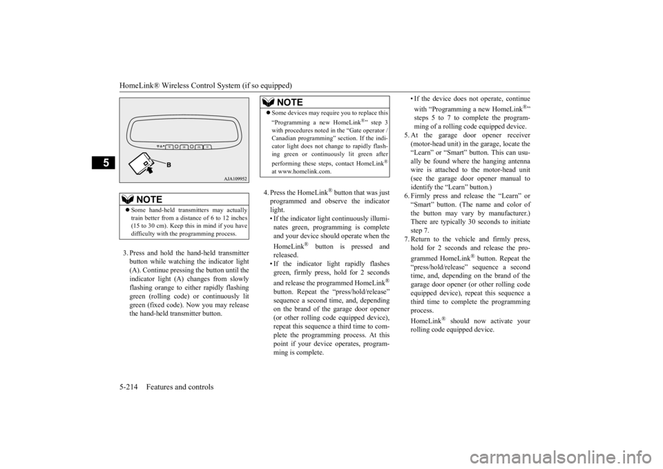
3. Press and hold the hand-held transmitter button while watching the indicator light(A). Continue pressing the button until theindicator light (A) changes from slowly flashing orange to either rapidly flashing green (rolling code) or continuously litgreen (fixed code). Now you may release the hand-held transmitter button.
4. Press the HomeLink
® button that was just
programmed and observe the indicatorlight. • If the indicator light continuously illumi- nates green, programming is completeand your device should
operate when the
HomeLink
® button is pressed and
released.• If the indicator light rapidly flashesgreen, firmly press, hold for 2 seconds and release the programmed HomeLink
®
button. Repeat the “press/hold/release” sequence a second time, and, depending on the brand of the garage door opener (or other rolling code equipped device),repeat this sequence a third time to com- plete the programming process. At this point if your device operates, program-ming is complete.
• If the device does not operate, continue with “Programming a new HomeLink
®”
steps 5 to 7 to complete the program- ming of a rolling code equipped device.
5. At the garage door opener receiver (motor-head unit) in the garage, locate the “Learn” or “Smart” button. This can usu-ally be found where the hanging antenna wire is attached to the motor-head unit (see the garage door opener manual toidentify the “Learn” button.)6. Firmly press and release the “Learn” or “Smart” button. (The name and color of the button may vary by manufacturer.)There are typically 30 seconds to initiate step 7. 7. Return to the vehicle and firmly press,hold for 2 seconds and release the pro- grammed HomeLink
® button. Repeat the
“press/hold/release” sequence a secondtime, and, depending on the brand of the garage door opener (or other rolling code equipped device), repeat this sequence athird time to complete the programming process. HomeLink
® should now activate your
rolling code equipped device.
NOTE
Some hand-held transmitters may actually train better from a distance of 6 to 12 inches (15 to 30 cm). Keep this in mind if you havedifficulty with the programming process.
NOTE
Some devices may require you to replace this “Programming a new HomeLink
®” step 3
with procedures noted in the “Gate operator / Canadian programming” section. If the indi- cator light does not change to rapidly flash-ing green or continuously lit green after performing these steps, contact HomeLink
®
at www.homelink.com.
BK0277700US.book
214 ページ 2019年3月8日 金曜日 午前9時23分
Page 390 of 427
Fuses
Vehicle care and maintenance 9-25
9
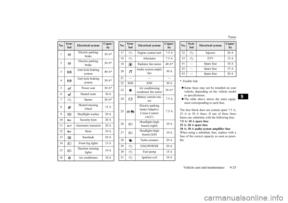
* : Fusible link Some fuses may not be installed on your vehicle, depending on the vehicle model or specifications. The table above shows the main equip- ment corresponding to each fuse.
The fuse block does not contain spare 7.5 A, 25 A or 30 A fuses. If one of these fusesburns out, substitute with the following fuse.7.5 A: 10 A spare fuse 25 A: 20 A spare fuse 30 A: 30 A audio system amplifier fuseWhen using a substitute fuse, replace with a fuse of the correct capacity as soon as possi- ble.
No.
Sym- bol
Electrical system
Capac-ity
1
Electric parking
brake
30 A
*
2
Electric parking
brake
30 A
*
3
Anti-lock braking
system
40 A
*
4
Anti-lock braking
system
30 A
*
5 Power seat 30 A
*
6 Heated seats 30 A 7Starter30 A
*
8
Heated steering
wheel
15 A
9 Headlight washer 20 A 10 Security horn 20 A 11 Automatic transaxle 20 A 12 Horn 10 A 13 Sunshade 20 A14 Front fog lights 15 A 15
Daytime running
lights
10 A
16 Air conditioner 10 A
17 Engine control unit 7.5 A 18 Alternator 7.5 A 19 Radiator fan motor 40 A
*
20
Audio system ampli-
fier
30 A
21 — — — 22 IOD IOD 30 A 23
Air conditioning condenser fan motor
30 A
*
24
Battery current sen-
sor
7.5 A
25
/
Electric parking brake/Adaptive Cruise Control
(ACC)
7.5 A
26
Headlight (high beam) (right)
10 A
27
Headlight (high beam) (left)
10 A
28 Turbo actuator 20 A 29 ENG/POWER 20 A 30 Fuel pump 15 A31 Ignition coil 10 ANo.
Sym- bol
Electrical system
Capac-ity
32 Injector 20 A 33 ETV 15 A #1 — Spare fuse 10 A #2 — Spare fuse 15 A#3 — Spare fuse 20 ANo.
Sym- bol
Electrical system
Capac-ity
BK0277700US.bo
ok 25 ページ 2019年3月8日 金曜日 午前9時23分