clock MITSUBISHI ECLIPSE CROSS 2020 Owner's Manual (in English)
[x] Cancel search | Manufacturer: MITSUBISHI, Model Year: 2020, Model line: ECLIPSE CROSS, Model: MITSUBISHI ECLIPSE CROSS 2020Pages: 427, PDF Size: 78.05 MB
Page 25 of 427
Filling the fuel tank 3-4 General information
3
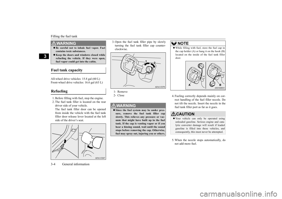
All-wheel drive vehicles: 15.8 gal (60 L) Front-wheel drive vehicles: 16.6 gal (63 L) 1. Before filling with fuel, stop the engine. 2. The fuel tank filler is located on the rear driver side of your vehicle. The fuel tank filler door can be openedfrom inside the vehicle with the fuel tank filler door release le
ver located at the left
side of the driver’s seat.
3. Open the fuel tank filler pipe by slowly turning the fuel tank filler cap counter- clockwise.
4. Fueling correctly depends mainly on cor- rect handling of the fuel filler nozzle. Do not tilt the nozzle. Insert the nozzle in thefuel tank filler port as far as it goes. 5. When the nozzle stops automatically, do not add more fuel.
Be careful not to inhale fuel vapor. Fuel contains toxic substances. Keep the doors and windows closed while refueling the vehicle. If they were open,fuel vapor could get into the cabin.
Fuel tank capacity Refueling
WA R N I N G
1- Remove 2- CloseWA R N I N G Since the fuel system may be under pres- sure, remove the fuel tank filler cap slowly. This relieves any pressure or vac- uum that might have built up in the fueltank. If the cap is venting vapor or if you hear a hissing sound, wait until the sound stops before removing the cap. Otherwise,fuel may spray out, injuring you or others.
NOTE
While filling with fuel, store the fuel cap in the cap holder (A) or hang it on the hook (B) located on the inside of the fuel tank filler door.CAUTION Your vehicle can only be operated using unleaded gasoline. Serious engine and cata- lytic converter damage will result if leadedgasoline is filled into these vehicles, and consequently, this must never be attempted.
BK0277700US.bo
ok 4 ページ 2019年3月8日 金曜日 午前9時23分
Page 26 of 427
Telematics Control Unit (TCU) (if so equipped)
General information 3-5
3
6. To re-install, turn the fuel tank filler pipe cap slowly clockwise until you hear click- ing sounds, then gently push the fuel tank filler door closed.
N00302500031
The Telematics Control Unit (TCU) uses amobile communication network to transmitnotifications (SOS emergency assis- tance/Information assistance) in case of emer- gency and vehicle information. The TCU alsoallows you to use your smartphone to operate some vehicle functions remotely.
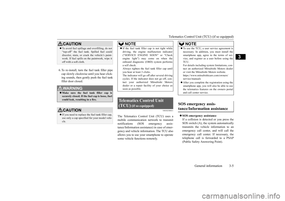
SOS emergency assistance If a collision is detected or you press theSOS switch (A), the system automatically transmits the vehicle information to an emergency call center, and will call theemergency call center. If necessary, the telephone call is forwarded to a PSAP (Public Safety Answering Point).
CAUTION To avoid fuel spillage and overfilling, do not “top-off” the fuel tank. Spilled fuel could discolor, stain, or crack the vehicle’s paint- work. If fuel spills on the paintwork, wipe it off with a soft cloth.WA R N I N G Make sure the fuel tank filler cap is securely closed. If the fuel cap is loose, fuel could leak, resulting in a fire.CAUTION If you need to replace the fuel tank filler cap, use only a cap specified for your model vehi- cle.
NOTE
If the fuel tank filler
cap is not tight while
driving, the engine malfunction indicator (“SERVICE ENGINE SOON” or “Check engine light”) may come on when the onboard diagnostic (OBD) system performsa self check. Always tighten the fuel tank filler cap until you hear at least 3 clicks.The indicator will go off after several driving cycles. If the indicator does not go off, con- tact your authorized Mitsubishi Motorsdealer or a repair facility of your choice as soon as possible.
Telematics Control Unit (TCU)
(if so equipped)
NOTE
To use the TCU, a user service agreement is necessary. In addition, you must install the smartphone app, agree to the terms of ser- vice, and register as a user before using the TCU.For details including system limitations, con- tact an authorized Mitsubishi Motors dealer or visit the Mitsubishi Motors website.https://www.mitsubishicars.com/owners/ service/manuals After you complete the registration using the smartphone app, you will also be able to use the telematics features on the owners portaland call center service.
SOS emergency assis- tance/Information assistance
BK0277700US.bo
ok 5 ページ 2019年3月8日 金曜日 午前9時23分
Page 153 of 427
4-wheel drive operation 5-72 Features and controls
5
N00542501087
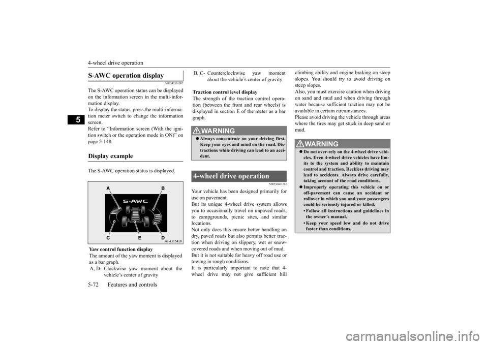
The S-AWC operation status can be displayed on the information screen in the multi-infor-mation display. To display the status, press the multi-informa- tion meter switch to change the informationscreen. Refer to “Information screen (With the igni- tion switch or the operation mode in ON)” onpage 5-148. The S-AWC operation status is displayed.
N00530601212
Your vehicle has been designed primarily for use on pavement. But its unique 4-wheel drive system allowsyou to occasionally travel on unpaved roads, to campgrounds, picnic sites, and similar locations.Not only does this ensure better handling on dry, paved roads but also permits better trac- tion when driving on slippery, wet or snow-covered roads and when moving out of mud. But it is not suitable for heavy off road use or towing in rough conditions.It is particularly important to note that 4- wheel drive may not give sufficient hill
climbing ability and engine braking on steep slopes. You should try to avoid driving on steep slopes. Also, you must exercise caution when drivingon sand and mud and when driving through water because sufficient traction may not be available in certain circumstances.Please avoid driving the vehicle through areas where the tires may get stuck in deep sand or mud.
S-AWC operation display
Display example
Yaw control function displayThe amount of the yaw
moment is displayed
as a bar graph. A, D- Clockwise yaw moment about the
vehicle’s center of gravity
B, C- Counterclockwise yaw moment
about the vehicle’s center of gravity
Traction control level display The strength of the traction control opera-tion (between the front and rear wheels) is displayed in section E of the meter as a bar graph.
WA R N I N G Always concentrate on your driving first. Keep your eyes and mi
nd on the road. Dis-
tractions while driving can lead to an acci- dent.
4-wheel drive operation
WA R N I N G Do not over-rely on the 4-wheel drive vehi- cles. Even 4-wheel drive vehicles have lim-its to the system and ability to maintain control and traction. Reckless driving may lead to accidents. Always drive carefully,taking account of the road conditions. Improperly operating this vehicle on or off-pavement can cause an accident or rollover in which you and your passengers could be seriously injured or killed.• Follow all instructions and guidelines inthe owner’s manual.• Keep your speed low and do not drivefaster than conditions.
BK0277700US.bo
ok 72 ページ 2019年3月8日 金曜日 午前9時23分
Page 162 of 427
Active Yaw Control (AYC) Features and controls 5-81
5
N00596700027
The Active Yaw Control (AYC) is a system with a yaw control function, that controls the left-right driving/braking force using the brakes. The yaw control function is a function that enhances vehicle cornering performance andvehicle stability with management of vehicle turning power (yaw moment) by controlling the drive power difference of the left andright wheels and the braking force when the vehicle does not turn in response to steering input, such as when the steering wheel isturned quickly or when driving on slippery road.
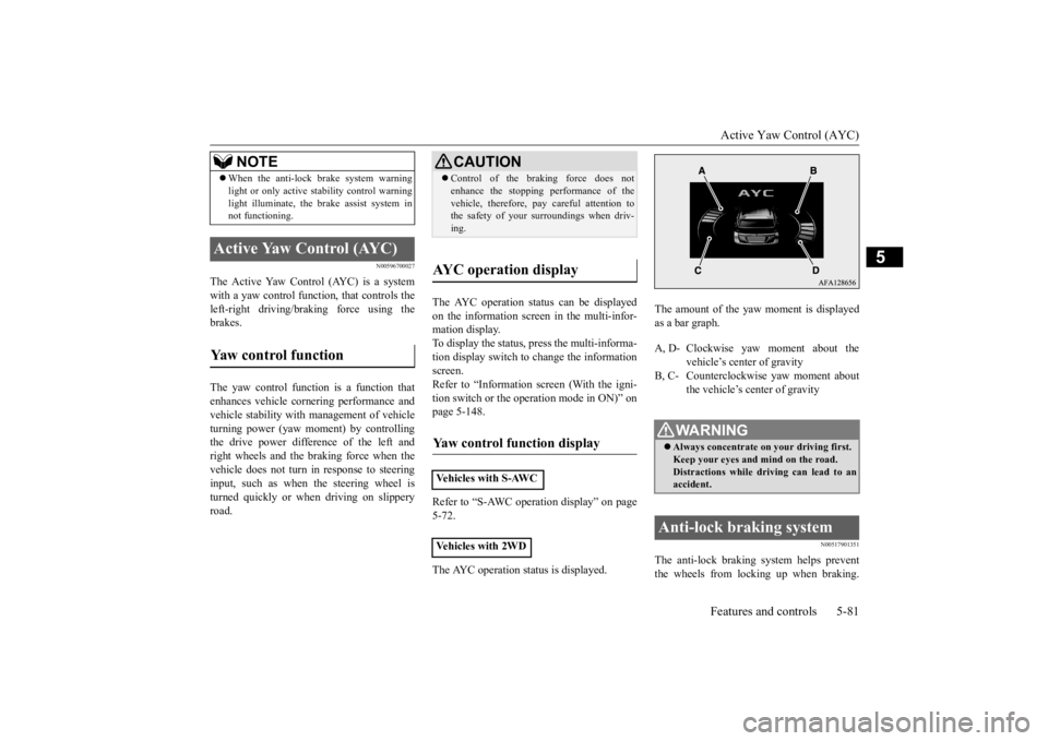
The AYC operation status can be displayed on the information screen in the multi-infor- mation display. To display the status, press the multi-informa-tion display switch to change the information screen. Refer to “Information screen (With the igni-tion switch or the operation mode in ON)” on page 5-148. Refer to “S-AWC operation display” on page 5-72. The AYC operation status is displayed.
The amount of the yaw moment is displayed as a bar graph.
N00517901351
The anti-lock braking system helps preventthe wheels from locking up when braking.
When the anti-lock brake system warning light or only active stability control warning light illuminate, the brake assist system in not functioning.
Active Yaw Control (AYC) Yaw control function
NOTE
CAUTION Control of the braking force does not enhance the stopping performance of the vehicle, therefore, pay careful attention to the safety of your surroundings when driv- ing.
AYC operation display Yaw control function display Vehicles with S-AWC Vehicles with 2WD
A, D- Clockwise yaw moment about the
vehicle’s center of gravity
B, C- Counterclockwise yaw moment about
the vehicle’s center of gravityWA R N I N G Always concentrate on your driving first. Keep your eyes and
mind on the road.
Distractions while driving can lead to anaccident.
Anti-lock braking system
BK0277700US.bo
ok 81 ページ 2019年3月8日 金曜日 午前9時23分
Page 266 of 427
Warning lights
Features and controls 5-185
5
N00520501856
This indicator is a part
of the onboard diag-
nostic (OBD) system which monitors the emissions, engine control system or continu-ously variable transmission (CVT) control system. If a problem is detected in one of these systems, this indicator illuminates orflashes. When the igniti
on switch is turned to
the “ON” position or the operation mode is put in ON, this indicator normally comes onand goes off after the engine has started. This indicator will come on if the fuel tank filler cap is not properly tightened. If this
indicator comes on and stays on after refuel- ing, stop the engine and check that the cap is properly tightened. (Turn the cap clockwise until you hear clicking sounds.)If this indicator does not go off after several seconds or lights up while driving, have the system checked as soon as possible at anauthorized Mitsubishi Motors dealer or a repair facility of your choice.
CAUTION When the warning light remains on or does not come on, there is the possibility that the parking brake cannot be operated or released. Immediately contact the nearest authorized Mitsubishi Motors dealer. Whenthe warning light comes on during driving, immediately stop the vehicle in a safe place, and contact an authorized Mitsubishi Motorsdealer. If you inevitably have to park, park the vehicle on level and stable ground, shift the selector lever in “P” (PARK) positionand place chocks or blocks.
Engine malfunction indicator (“SERVICE ENGINE SOON” or “Check engine light”)
CAUTION Driving for a long time with the engine mal- function indicator on may cause more dam- age to the emission control system. This could also affect fuel economy and drivabil-ity. If this indicator does not come on when the ignition switch is turned to the “ON” posi- tion or the operation mode is put in ON, have the system checked at an authorizedMitsubishi Motors dealer or a repair facility of your choice.
If the engine malfunction indicator comes on while the engine is running, avoid driving at high speeds. During vehicle operation with the indicator on, the vehicle may not accelerate when youdepress the accelerator pedal. When the vehicle is stationary with the indi- cator on, you must depress the brake pedalmore firmly than usual since the engine idling speed is higher than usual and a vehi- cle with continuously variable transmission(CVT) has a stronger tendency to creep for- ward.NOTE
Do not disconnect the battery cable when the engine malfunction indicator (“SERVICEENGINE SOON” or “Check engine light”) is on. The engine electronic control module storescritical OBD information (especially exhaust emission data), which may be lost if the bat- tery cable is disconnected while the enginemalfunction indicator is on. This will make it difficult to diagnose the cause of future prob- lems.CAUTION
BK0277700US.book
185 ページ 2019年3月8日 金曜日 午前9時23分
Page 356 of 427
Jack and tools
For emergencies 8-5
8
6. When you do not see any more steam or spray, open the hood. Look for obvious leaks, such as a split radiator hose. Be careful as components will be hot. Anyleak source must be repaired. 7. If there is no obvious leak source, check the coolant level in the engine coolantreserve tank. If there is none, or if it is too low, slowly add coolant. 8. If the engine coolant reserve tank needscoolant, you will probably also need toadd coolant to the radiator. Do not loosen or remove the radiator cap until the engine has cooled down. 9. Start the engine, and slowly add coolant, up to the bottom of the filler neck. Useplain water if you have to (and replace it with the right coolant as soon as possible).
10. Replace the radiator cap and tighten it
fully. Check the engine coolant tempera- ture display on the multi-information dis- play. You can start driving again when thehigh coolant temperature warning does not come on.
11. Have the system inspected by your autho-
rized Mitsubishi Motors dealer or a repair facility of your choice.
N00836601435
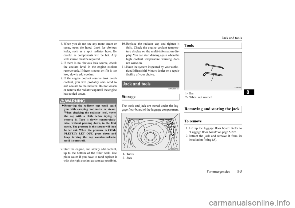
The tools and jack are stored under the lug- gage floor board of the luggage compartment.
1. Lift up the luggage floor board. Refer to “Luggage floor board” on page 5-226. 2. Retract the jack and remove it from its installation fitting (A).
WA R N I N G Removing the radiator cap could scald you with escaping hot water or steam.When checking the radiator level, cover the cap with a cloth before trying to remove it. Turn it slowly counterclock-wise, without pressing down, to the first notch. The pressure in the system will then be let out. When the pressure is COM-PLETELY LET OUT, press down and keep turning the cap counterclockwise until it comes off.
Jack and tools Storage 1- Tools 2- Jack
Tools 1- Bar2- Wheel nut wrenchRemoving and storing the jack To remove
BK0277700US.bo
ok 5 ページ 2019年3月8日 金曜日 午前9時23分
Page 358 of 427
How to change a tire
For emergencies 8-7
8
N00849601341
The compact spare tire is stored under the luggage floor board of the luggage compart-ment. It is designed to save space in the lug- gage compartment. Its lighter weight makes it easier to use if a flat tire occurs.
N00849701384
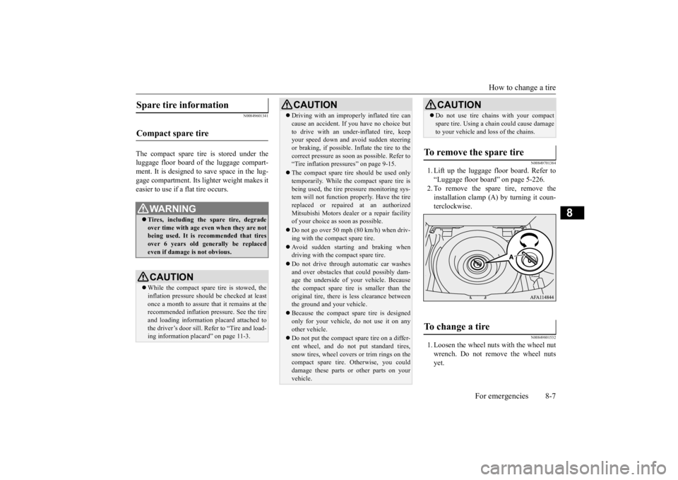
1. Lift up the luggage floor board. Refer to“Luggage floor board” on page 5-226.2. To remove the spare tire, remove theinstallation clamp (A) by turning it coun- terclockwise.
N00849801532
1. Loosen the wheel nuts with the wheel nut wrench. Do not remove the wheel nuts yet.
Spare tire information Compact spare tire
WA R N I N G Tires, including the spare tire, degrade over time with age even when they are notbeing used. It is recommended that tires over 6 years old generally be replaced even if damage is not obvious.CAUTION While the compact spare tire is stowed, the inflation pressure should be checked at least once a month to assure that it remains at therecommended inflation pressure. See the tire and loading information placard attached to the driver’s door sill. Refer to “Tire and load- ing information placard” on page 11-3.
Driving with an improperly inflated tire can cause an accident. If you have no choice but to drive with an under-inflated tire, keep your speed down and avoid sudden steering or braking, if possible
. Inflate the tire to the
correct pressure as soon as possible. Refer to “Tire inflation pressures” on page 9-15. The compact spare tire should be used only temporarily. While the compact spare tire is being used, the tire pressure monitoring sys-tem will not function properly. Have the tire replaced or repaired at an authorized Mitsubishi Motors dealer or a repair facilityof your choice as soon as possible. Do not go over 50 mph (80 km/h) when driv- ing with the compact spare tire. Avoid sudden starting and braking when driving with the compact spare tire. Do not drive through automatic car washes and over obstacles that could possibly dam- age the underside of your vehicle. Because the compact spare tire is smaller than theoriginal tire, there is less clearance between the ground and your vehicle. Because the compact spare tire is designed only for your vehicle, do not use it on any other vehicle. Do not put the compact spare tire on a differ- ent wheel, and do not put standard tires, snow tires, wheel covers or trim rings on the compact spare tire. Otherwise, you coulddamage these parts or other parts on your vehicle.CAUTION
Do not use tire chains with your compact spare tire. Using a chain could cause damage to your vehicle and loss of the chains.
To remove the spare tire To change a tire
CAUTION
BK0277700US.bo
ok 7 ページ 2019年3月8日 金曜日 午前9時23分
Page 360 of 427
How to change a tire
For emergencies 8-9
8
5. Remove the wheel nuts with the wheel nut wrench, then take the wheel off.
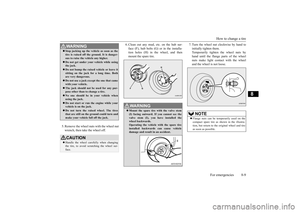
6. Clean out any mud, etc. on the hub sur- face (F), hub bolts (G) or in the installa- tion holes (H) in the wheel, and then mount the spare tire.
7. Turn the wheel nut clockwise by hand to initially tighten them. Temporarily tighten the wheel nuts by hand until the flange parts of the wheelnuts make light contact with the wheel and the wheel is not loose.
WA R N I N G Stop jacking up the vehicle as soon as the tire is raised off the ground. It is danger- ous to raise the vehicle any higher. Do not get under your vehicle while using the jack. Do not bump the raised vehicle or leave it sitting on the jack for a long time. Both are very dangerous. Do not use a jack except the one that came with your vehicle. The jack should not be used for any pur- pose other than to change a tire. No one should be in your vehicle when using the jack. Do not start or run the engine while your vehicle is on the jack. Do not turn the raised wheel. The tires that are still on the ground could turn and make your vehicle fall off the jack.CAUTION Handle the wheel carefully when changing the tire, to avoid scratching the wheel sur- face.
WA R N I N G Mount the spare tire with the valve stem (I) facing outward. If you cannot see the valve stem (I), you have installed the wheel backwards.Operating the vehicle with the spare tire installed backwards can cause vehicle damage and result in an accident.
NOTE
Flange nuts can be temporarily used on the compact spare tire as shown in the illustra- tion, but return to the original wheel and tire as soon as possible.
BK0277700US.bo
ok 9 ページ 2019年3月8日 金曜日 午前9時23分
Page 361 of 427
How to change a tire 8-10 For emergencies
8
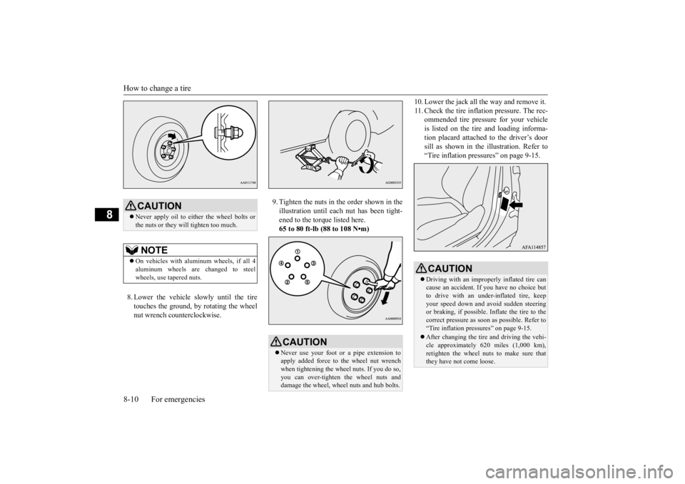
8. Lower the vehicle slowly until the tire touches the ground, by rotating the wheel nut wrench counterclockwise.
9. Tighten the nuts in the order shown in the illustration until each nut has been tight- ened to the torque listed here.65 to 80 ft-lb (88 to 108 N•m)
10. Lower the jack all the way and remove it. 11. Check the tire inflation pressure. The rec-
ommended tire pressure for your vehicle is listed on the tire and loading informa-tion placard attached to the driver’s door sill as shown in the illustration. Refer to “Tire inflation pressures” on page 9-15.
CAUTION Never apply oil to either the wheel bolts or the nuts or they will tighten too much.NOTE
On vehicles with aluminum wheels, if all 4 aluminum wheels are changed to steel wheels, use tapered nuts.
CAUTION Never use your foot or a pipe extension to apply added force to the wheel nut wrenchwhen tightening the wheel nuts. If you do so, you can over-tighten the wheel nuts and damage the wheel, wheel nuts and hub bolts.
CAUTION Driving with an improperly inflated tire can cause an accident. If
you have no choice but
to drive with an under-inflated tire, keep your speed down and avoid sudden steering or braking, if possible
. Inflate the tire to the
correct pressure as soon as possible. Refer to “Tire inflation pressures” on page 9-15. After changing the tire and driving the vehi- cle approximately 620 miles (1,000 km), retighten the wheel nuts to make sure thatthey have not come loose.
BK0277700US.bo
ok 10 ページ 2019年3月8日 金曜日 午前9時23分
Page 362 of 427
Towing
For emergencies 8-11
8
N00832300033
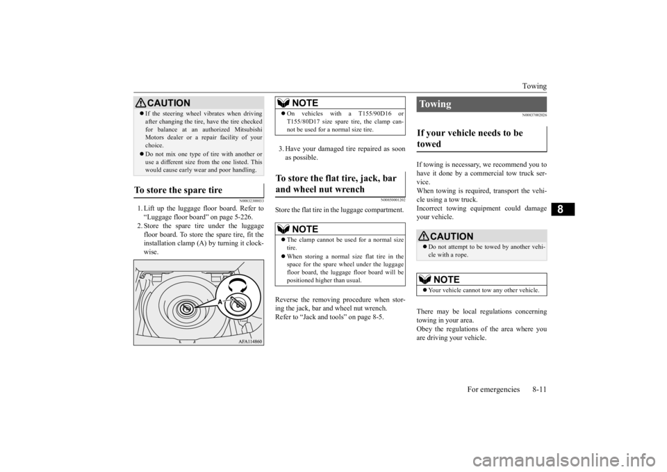
1. Lift up the luggage floor board. Refer to “Luggage floor board” on page 5-226. 2. Store the spare tire under the luggagefloor board. To store the spare tire, fit the installation clamp (A) by turning it clock- wise.
3. Have your damaged tire repaired as soon as possible.
N00850001202
Store the flat tire in the luggage compartment. Reverse the removing procedure when stor- ing the jack, bar and wheel nut wrench. Refer to “Jack and tools” on page 8-5.
N00837002026
If towing is necessary, we recommend you to have it done by a commercial tow truck ser- vice. When towing is required, transport the vehi-cle using a tow truck.Incorrect towing equipment could damage your vehicle. There may be local regulations concerning towing in your area. Obey the regulations of the area where you are driving your vehicle.
If the steering wheel vibrates when driving after changing the tire, have the tire checked for balance at an authorized Mitsubishi Motors dealer or a repair facility of your choice. Do not mix one type of tire with another or use a different size from the one listed. Thiswould cause early wear and poor handling.
To store the spare tire
CAUTION
NOTE
On vehicles with a T155/90D16 or T155/80D17 size spare tire, the clamp can- not be used for a normal size tire.
To store the flat tire, jack, bar and wheel nut wrench
NOTE
The clamp cannot be us
ed for a normal size
tire. When storing a normal size flat tire in the space for the spare wheel under the luggagefloor board, the luggage floor board will be positioned higher than usual.
To w i n g If your vehicle needs to be towed
CAUTION Do not attempt to be towed by another vehi- cle with a rope.NOTE
Your vehicle cannot tow any other vehicle.
BK0277700US.bo
ok 11 ページ 2019年3月8日 金曜日 午前9時23分