MITSUBISHI ENDEAVOR 2004 Service Repair Manual
Manufacturer: MITSUBISHI, Model Year: 2004, Model line: ENDEAVOR, Model: MITSUBISHI ENDEAVOR 2004Pages: 3870, PDF Size: 98.47 MB
Page 791 of 3870
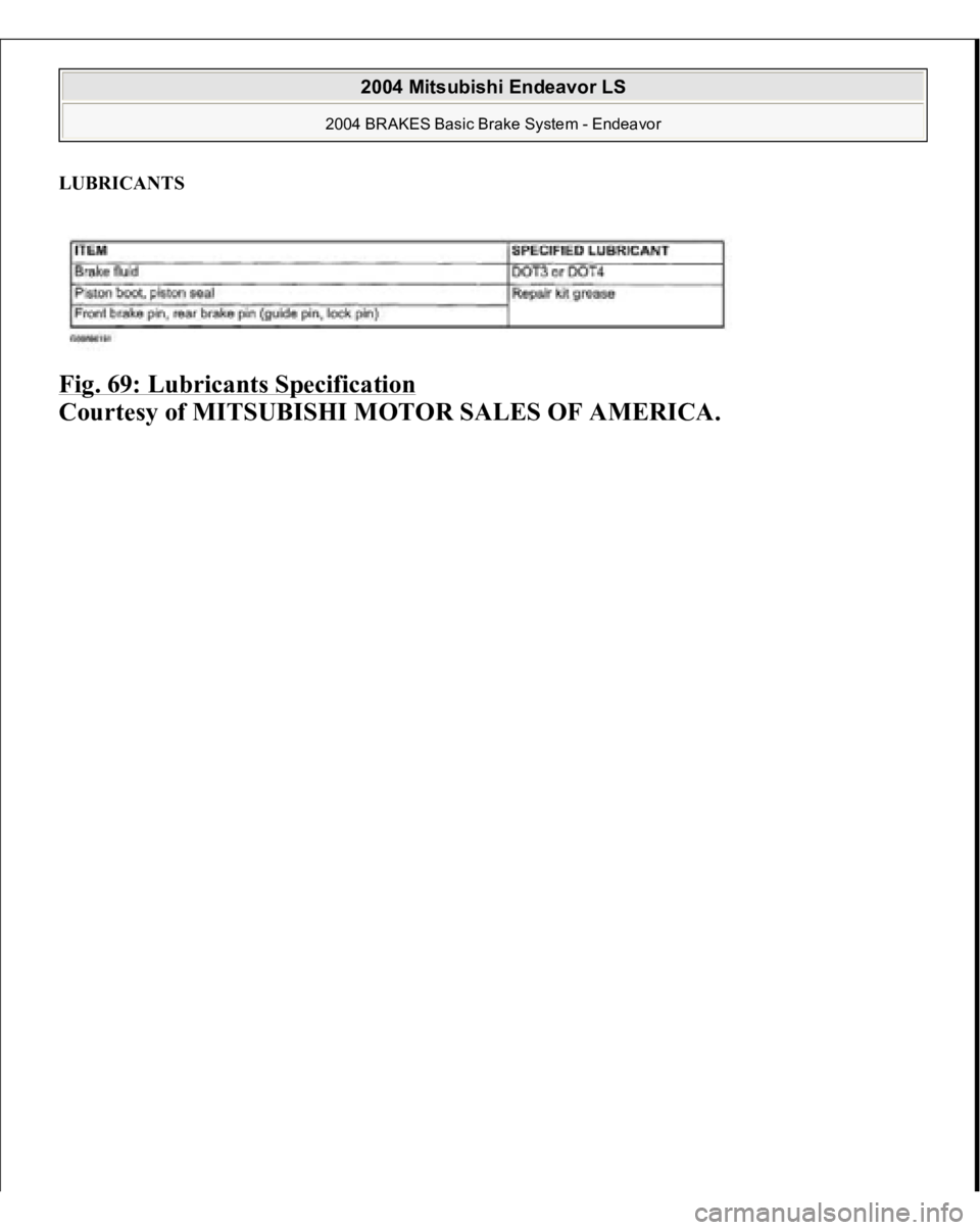
LUBRICANTS Fig. 69: Lubricants Specification
Courtesy of MITSUBISHI MOTOR SALES OF AMERICA.
2004 Mitsubishi Endeavor LS
2004 BRAKES Basic Brake System - Endeavor
Page 792 of 3870
2004 ENGINE COOLING
Electric Cooling Fans - Endeavor
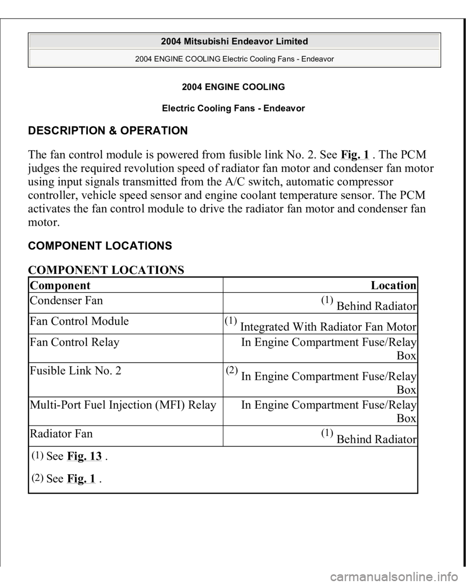
DESCRIPTION & OPERATION The fan control module is powered from fusible link No. 2. See Fig. 1
. The PCM
judges the required revolution speed of radiator fan motor and condenser fan motor
using input signals transmitted from the A/C switch, automatic compressor
controller, vehicle speed sensor and engine coolant temperature sensor. The PCM
activates the fan control module to drive the radiator fan motor and condenser fan
motor. COMPONENT LOCATIONS COMPONENT LOCATIONS Component
Location
Condenser Fan
(1) Behind Radiator
Fan Control Module
(1) Integrated With Radiator Fan Motor
Fan Control Relay
In Engine Compartment Fuse/Relay
Box
Fusible Link No. 2
(2) In Engine Compartment Fuse/Relay
Box
Multi-Port Fuel Injection (MFI) Relay
In Engine Compartment Fuse/Relay
Box
Radiator Fan
(1) Behind Radiator
(1)
See Fig. 13
.
(2)
See Fig. 1
.
2004 Mitsubishi Endeavor Limited
2004 ENGINE COOLING Electric Cooling Fans - Endeavor
2004 Mitsubishi Endeavor Limited
2004 ENGINE COOLING Electric Cooling Fans - Endeavor
Page 793 of 3870
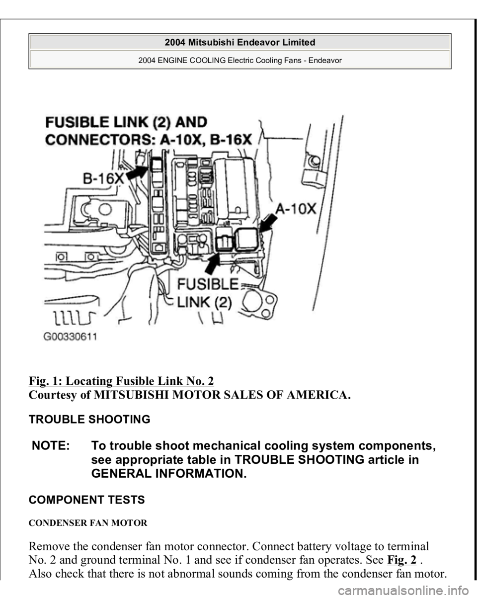
Fig. 1: Locating Fusible Link No. 2
Courtesy of MITSUBISHI MOTOR SALES OF AMERICA.
TROUBLE SHOOTING
COMPONENT TESTS CONDENSER FAN MOTOR Remove the condenser fan motor connector. Connect battery voltage to terminal No. 2 and ground terminal No. 1 and see if condenser fan operates. See Fig. 2
.
Also check that there is not abnormal sounds comin
g from the condenser fan motor.
NOTE: To trouble shoot mechanical cooling system components,
see appropriate table in TROUBLE SHOOTING article in
GENERAL INFORMATION.
2004 Mitsubishi Endeavor Limited
2004 ENGINE COOLING Electric Cooling Fans - Endeavor
Page 794 of 3870
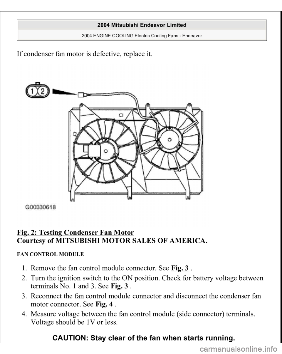
If condenser fan motor is defective, replace it.
Fig. 2: Testing Condenser Fan Motor
Courtesy of MITSUBISHI MOTOR SALES OF AMERICA.
FAN CONTROL MODULE 1. Remove the fan control module connector. See Fig. 3
.
2. Turn the ignition switch to the ON position. Check for battery voltage between
terminals No. 1 and 3. See Fig. 3
.
3. Reconnect the fan control module connector and disconnect the condenser fan
motor connector. See Fig. 4
.
4. Measure voltage between the fan control module (side connector) terminals.
Voltage should be 1V or less.
CAUTION: Stay clear of the fan when starts running.
2004 Mitsubishi Endeavor Limited
2004 ENGINE COOLING Electric Cooling Fans - Endeavor
Page 795 of 3870
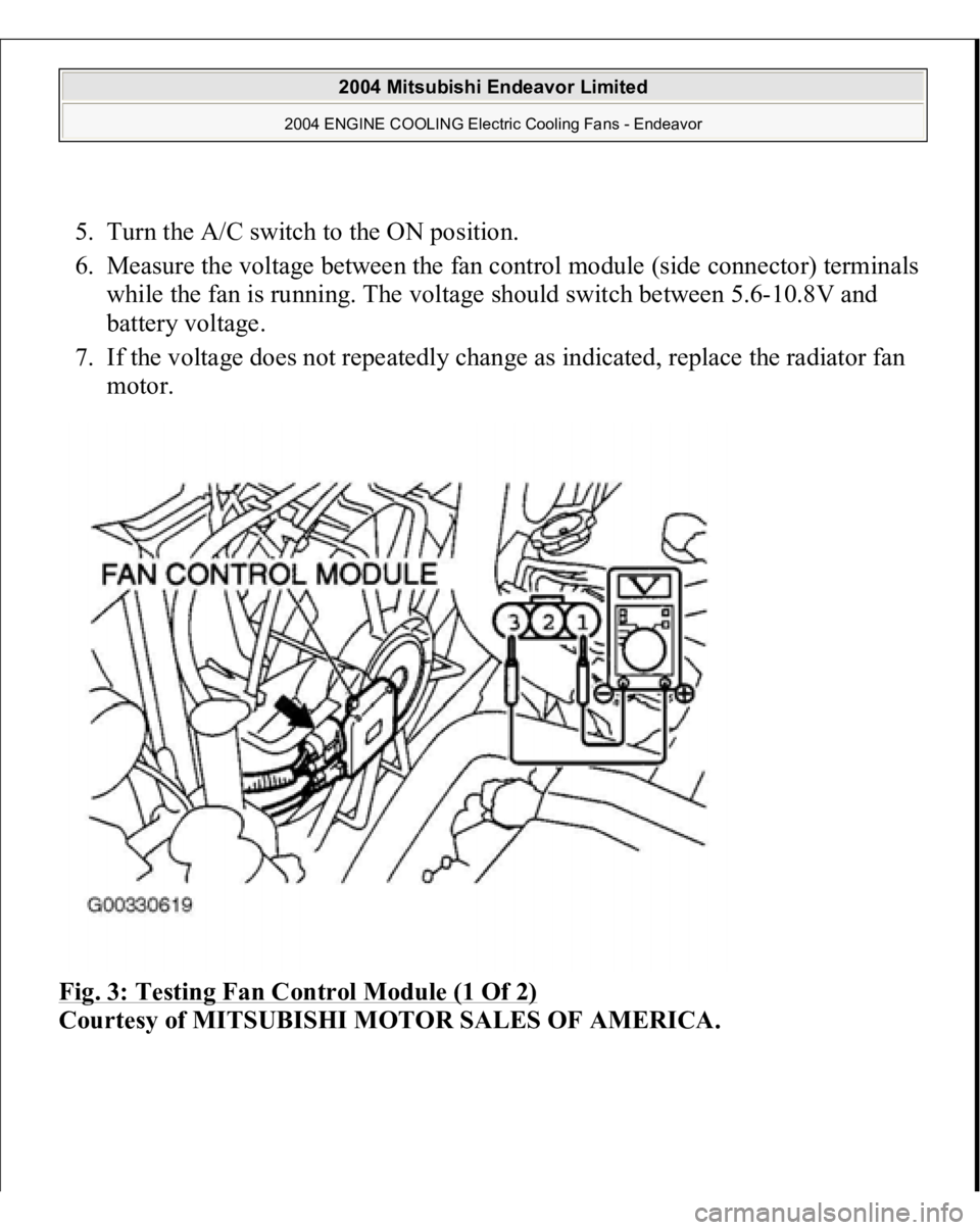
5. Turn the A/C switch to the ON position.
6. Measure the voltage between the fan control module (side connector) terminals
while the fan is running. The voltage should switch between 5.6-10.8V and
battery voltage.
7. If the voltage does not repeatedly change as indicated, replace the radiator fan
motor.
Fig. 3: Testing Fan Control Module (1 Of 2)
Courtesy of MITSUBISHI MOTOR SALES OF AMERICA.
2004 Mitsubishi Endeavor Limited
2004 ENGINE COOLING Electric Cooling Fans - Endeavor
Page 796 of 3870
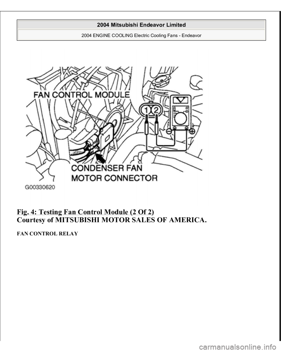
Fig. 4: Testing Fan Control Module (2 Of 2)
Courtesy of MITSUBISHI MOTOR SALES OF AMERICA.
FAN CONTROL RELAY
2004 Mitsubishi Endeavor Limited
2004 ENGINE COOLING Electric Cooling Fans - Endeavor
Page 797 of 3870
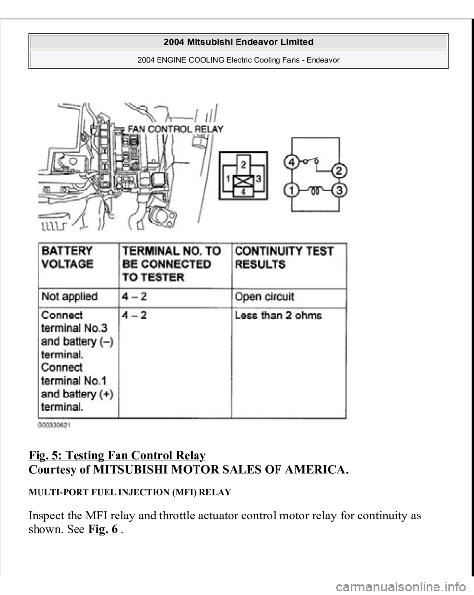
Fig. 5: Testing Fan Control Relay
Courtesy of MITSUBISHI MOTOR SALES OF AMERICA.
MULTI-PORT FUEL INJECTION (MFI) RELAY Inspect the MFI relay and throttle actuator control motor relay for continuity as
shown. See Fi
g. 6 .
2004 Mitsubishi Endeavor Limited
2004 ENGINE COOLING Electric Cooling Fans - Endeavor
Page 798 of 3870
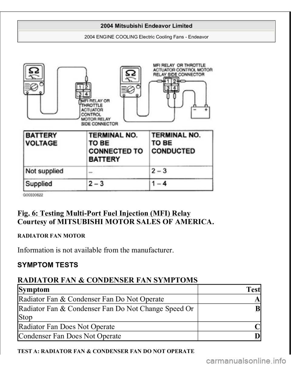
Fig. 6: Testing Multi
-Port Fuel Injection (MFI) Relay
Courtesy of MITSUBISHI MOTOR SALES OF AMERICA.
RADIATOR FAN MOTOR Information is not available from the manufacturer. SYMPTOM TESTS RADIATOR FAN & CONDENSER FAN SYMPTOMS TEST A: RADIATOR FAN & CONDENSER FAN DO NOT OPERATESymptom
Test
Radiator Fan & Condenser Fan Do Not Operate
A
Radiator Fan & Condenser Fan Do Not Change Speed Or
Stop
B
Radiator Fan Does Not Operate
C
Condenser Fan Does Not Operate
D
2004 Mitsubishi Endeavor Limited
2004 ENGINE COOLING Electric Cooling Fans - Endeavor
Page 799 of 3870
Technical Descriptio
n
The cause could be a malfunction of the fan control module power supply or
ground circuit. The cause could also be a malfunction of the fan control module or the PCM.
Troubleshooting Hints
Malfunction of fusible link. Malfunction of fan control relay. Malfunction of MFI relay. Malfunction of radiator fan motor. Malfunction of condenser fan motor. Malfunction of fan control module. Malfunction of PCM. Damaged wiring harness or connector.
Diagnosis 1. Disconnect fan control module connector A-23. See Fig. 7
. Measure for
voltage between terminal No. 3 (harness side of the connector) and ground
when ignition switch is turned to the ON position. If battery voltage is not
achieved, go to next step. If battery voltage is achieved, go to step 8 .
2. Check fan control relay. See FAN CONTROL RELAY under
COMPONENTS TESTS. If fan control relay is okay, go to next step. If fan
control relay is not okay, replace it and retest.
3. Check the MFI relay. See MULTI
-PORT FUEL INJECTION (MFI)
RELAY
under COMPONENT TESTS. If MFI relay is okay, go to next step. If
MFI relay is not okay, replace it and retest.
4. Check for harness damage in Black/Yellow wire between fusible link No. 2
and terminal No. 4 of fan control relay connector A-10X. See Fig. 8
. If wire is
okay, go to next step. If wire is damaged, repair or replace as necessary and
retest.
5. Check for harness damage in Blue wire between terminal No. 2 of fan control
rela
y connector
A-10X and terminal No. 3 of fan control module connector A-
2004 Mitsubishi Endeavor Limited
2004 ENGINE COOLING Electric Cooling Fans - Endeavor
Page 800 of 3870
23. See Fig. 7
and Fig.
8 . If wire is okay, go to next step. If wire is damaged,
repair or replace as necessary and retest.
6. Check intermediate connector A-13 for loose, corroded, or damaged terminals,
or terminals pushed back in the connector. See Fig. 9
. If intermediate
connector is okay, go to next step. If connector A-13 is not okay, repair or
replace as necessary and retest.
7. Check for harness damage in Red wire between terminal No. 4 of MFI relay
connector B-16X and terminal No. 1 of fan control relay connector A-10X. See
Fig. 8
and Fig. 10
. If wire is okay, go to next step. If wire is damaged, repair
or replace as necessary and retest.
8. Check for harness damage between terminal No. 3 of fan control relay
connector A-10X and ground. See Fig. 8
. If wire is damaged, repair it and
retest. If wire is okay, retest.
9. Disconnect fan control module connector A-23. See Fig. 7
. Measure resistance
between terminal No. 1 of fan control module connector A-23 (harness side of
connector) and ground. If the resistance is 2 ohms or more, go to next step. If
resistance is less than 2 ohms, go to step 11 .
10. Check the harness wires between terminal No. 1 of fan control module
connector A-23 and ground. If harness wires are okay go to next step. If
harness wires are damaged, repair as necessary and retest.
11. Disconnect all connectors from the PCM. Connect Power Plant ECU Check
Harness (MB991923) between the PCM and the body-side harness connector.
See Fig. 12
. Start the engine and allow it to idle. Measure the output circuit
volta
ge between terminal No. 10 and
ground. See Fig. 12
. If the volta
ge when
NOTE: First inspect terminal No. 7 of intermediate connector
A-13. See Fig. 9
. Then inspect the wires. If intermediate
connector A-13 is damaged, repair or replace as
necessary and retest.
NOTE: Measure the output circuit voltage at terminal No. 10 of
PCM connector B-18 (Green) by using Power Plant ECU
Check Harness (MB991923). See Fig. 11
and Fig. 12
.
2004 Mitsubishi Endeavor Limited
2004 ENGINE COOLING Electric Cooling Fans - Endeavor