MITSUBISHI ENDEAVOR 2004 Service Repair Manual
ENDEAVOR 2004
MITSUBISHI
MITSUBISHI
https://www.carmanualsonline.info/img/19/57105/w960_57105-0.png
MITSUBISHI ENDEAVOR 2004 Service Repair Manual
Page 1979 of 3870
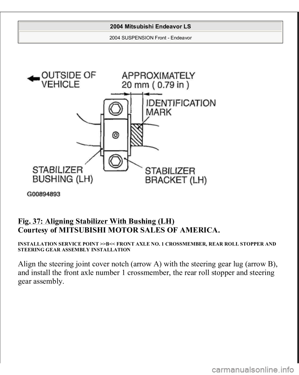
Fig. 37: Aligning Stabilizer With Bushing (LH)
Courtesy of MITSUBISHI MOTOR SALES OF AMERICA.
INSTALLATION SERVICE POINT >>B<< FRONT AXLE NO. 1 CROSSMEMBER, REAR ROLL STOPPER AND
STEERING GEAR ASSEMBLY INSTALLATION Align the steering joint cover notch (arrow A) with the steering gear lug (arrow B),
and install the front axle number 1 crossmember, the rear roll stopper and steering
gear assembly.
2004 Mitsubishi Endeavor LS 2004 SUSPENSION Front - Endeavor
Page 2886 of 3870
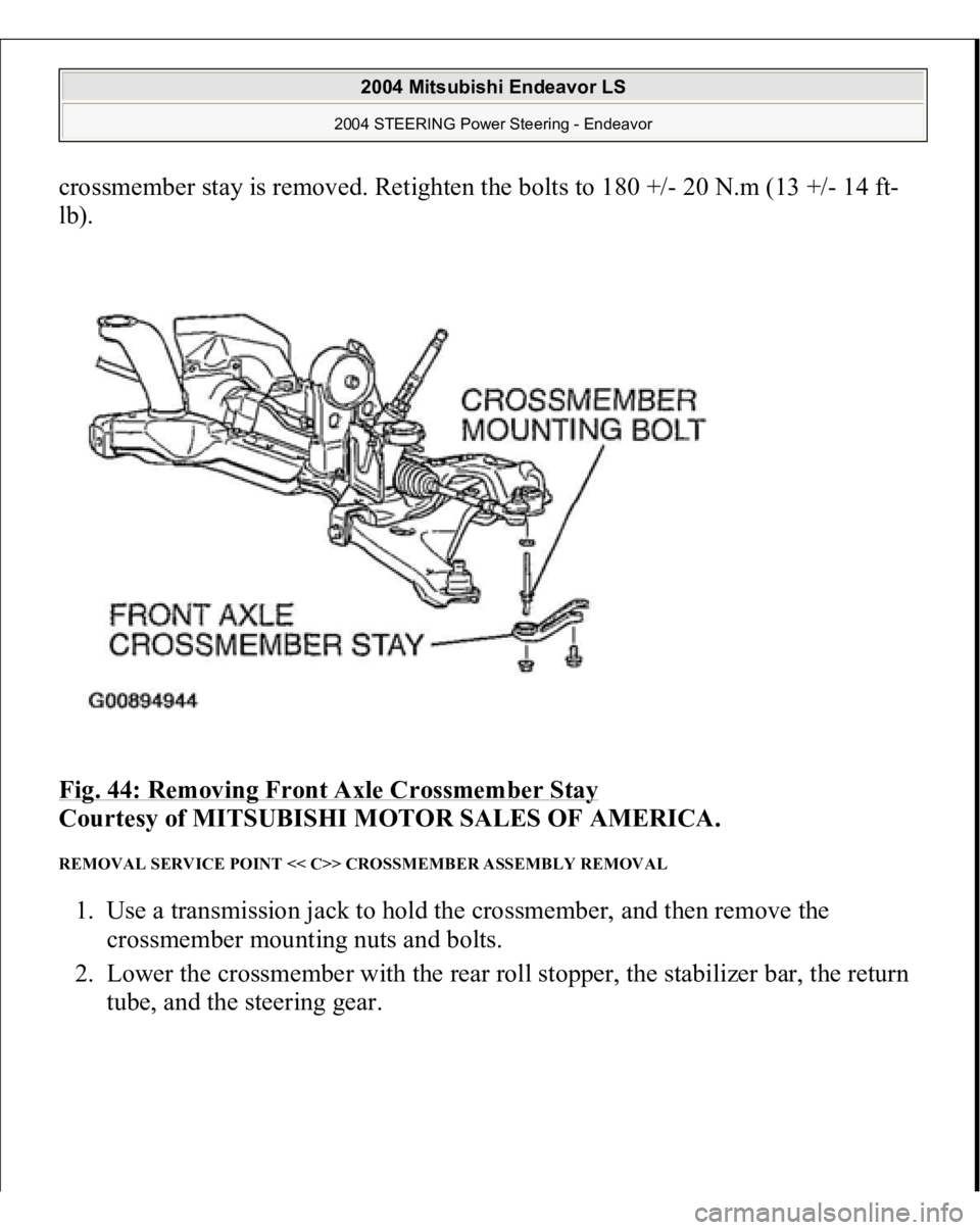
crossmember stay is removed. Retighten the bolts to 180 +/- 20 N.m (13 +/- 14 ft-
lb).
Fig. 44: Removing Front Axle Crossmember Stay
Courtesy of MITSUBISHI MOTOR SALES OF AMERICA.
REMOVAL SERVICE POINT << C>> CROSSMEMBER ASSEMBLY REMOVAL 1. Use a transmission jack to hold the crossmember, and then remove the
crossmember mounting nuts and bolts.
2. Lower the crossmember with the rear roll stopper, the stabilizer bar, the return
tube, and the steerin
g gear.
2004 Mitsubishi Endeavor LS
2004 STEERING Power Steering - Endeavor
Page 3037 of 3870
2004 SUSPENSION
Rear - Endeavor
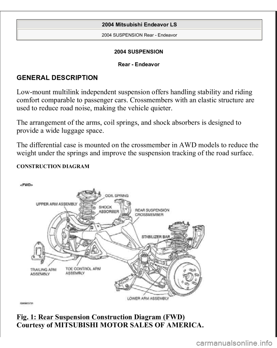
GENERAL DESCRIPTION Low-mount multilink independent suspension offers handling stability and riding
comfort comparable to passenger cars. Crossmembers with an elastic structure are
used to reduce road noise, making the vehicle quieter.
The arrangement of the arms, coil springs, and shock absorbers is designed to
provide a wide luggage space.
The differential case is mounted on the crossmember in AWD models to reduce the
weight under the springs and improve the suspension tracking of the road surface. CONSTRUCTION DIAGRAM Fig. 1: Rear Suspension Construction Diagram (FWD)
Courtesy of MITSUBISHI MOTOR SALES OF AMERICA.
2004 Mitsubishi Endeavor LS 2004 SUSPENSION Rear - Endeavor
2004 Mitsubishi Endeavor LS 2004 SUSPENSION Rear - Endeavor
Page 3052 of 3870
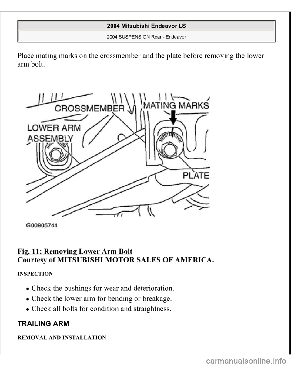
Place mating marks on the crossmember and the plate before removing the lower
arm bolt.
Fig. 11: Removing Lower Arm Bolt
Courtesy of MITSUBISHI MOTOR SALES OF AMERICA.
INSPECTION
Check the bushings for wear and deterioration. Check the lower arm for bending or breakage. Check all bolts for condition and straightness.
TRAILING ARM REMOVAL AND INSTALLATION
2004 Mitsubishi Endeavor LS 2004 SUSPENSION Rear - Endeavor
Page 3056 of 3870
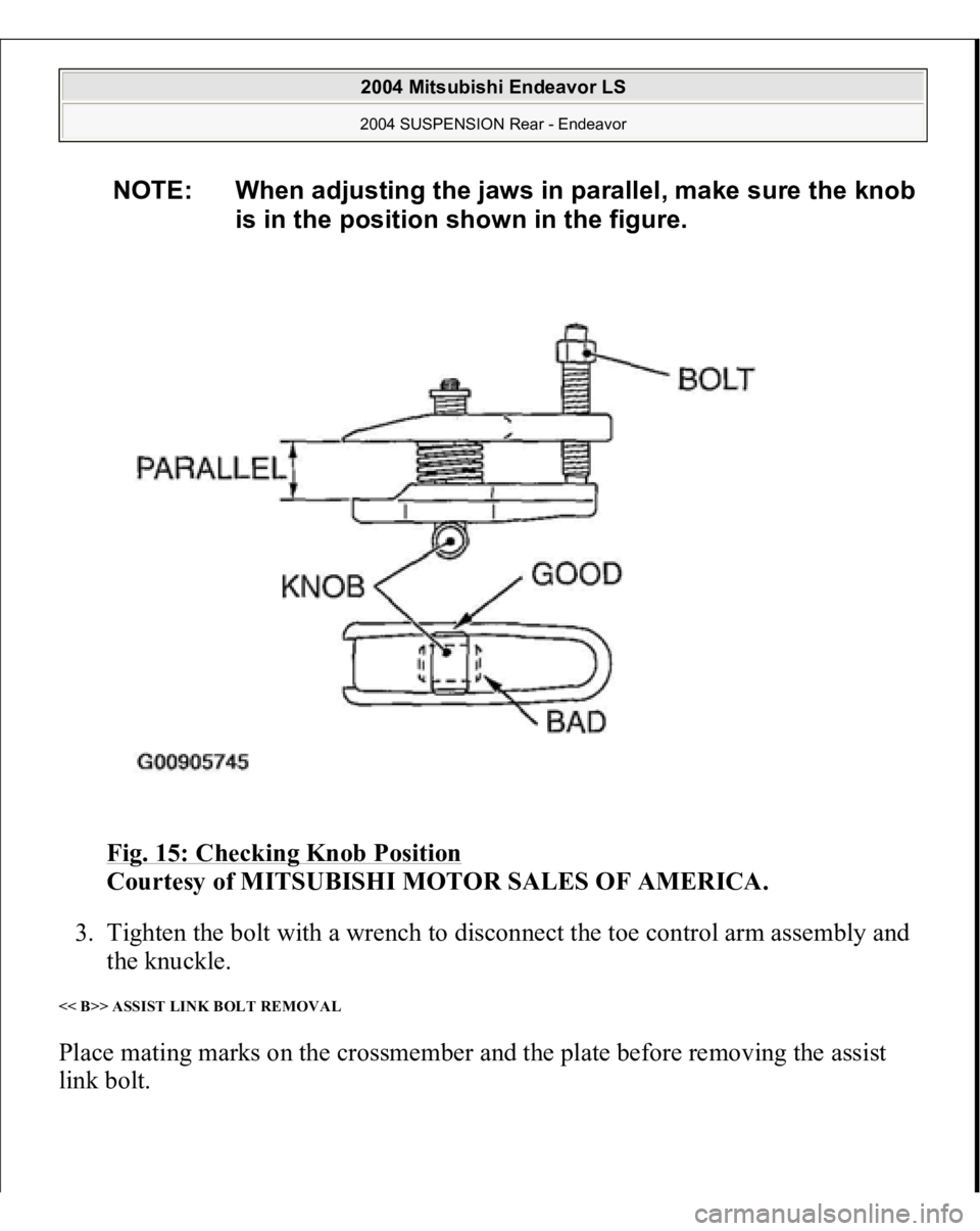
Fig. 15: Checking Knob Position
Courtesy of MITSUBISHI MOTOR SALES OF AMERICA.
3. Tighten the bolt with a wrench to disconnect the toe control arm assembly and
the knuckle.
<< B>> ASSIST LINK BOLT REMOVAL Place mating marks on the crossmember and the plate before removing the assist
link bolt.
NOTE: When adjusting the jaws in parallel, make sure the knob
is in the position shown in the figure.
2004 Mitsubishi Endeavor LS 2004 SUSPENSION Rear - Endeavor
Page 3074 of 3870
2. If the dust cover is cracked or damaged, replace the stabilizer bar link
assembly. REAR SUSPENSION CROSSMEMBER REMOVAL AND INSTALLATION < FWD>
NOTE: Cracks or damage of the dust cover may cause damage
to the ball joint.
CAUTION: For vehicles with ABS, be careful when handling the
pole piece at the tip of the ABS sensor so as not to
damage it by striking against other parts.
2004 Mitsubishi Endeavor LS 2004 SUSPENSION Rear - Endeavor
Page 3075 of 3870
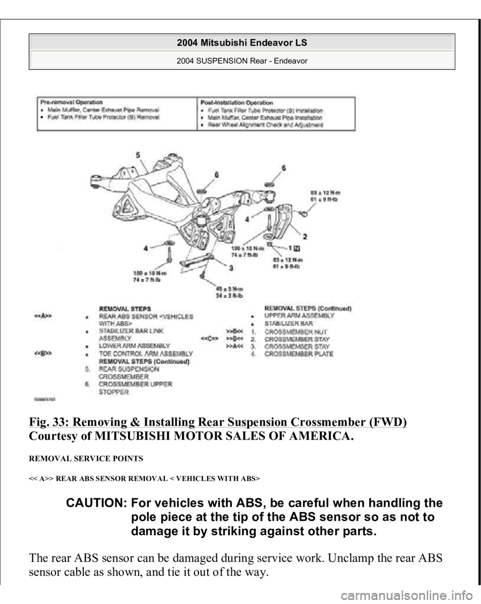
Fig. 33: Removing & Installing Rear Suspension Crossmember (FWD)
Courtesy of MITSUBISHI MOTOR SALES OF AMERICA.
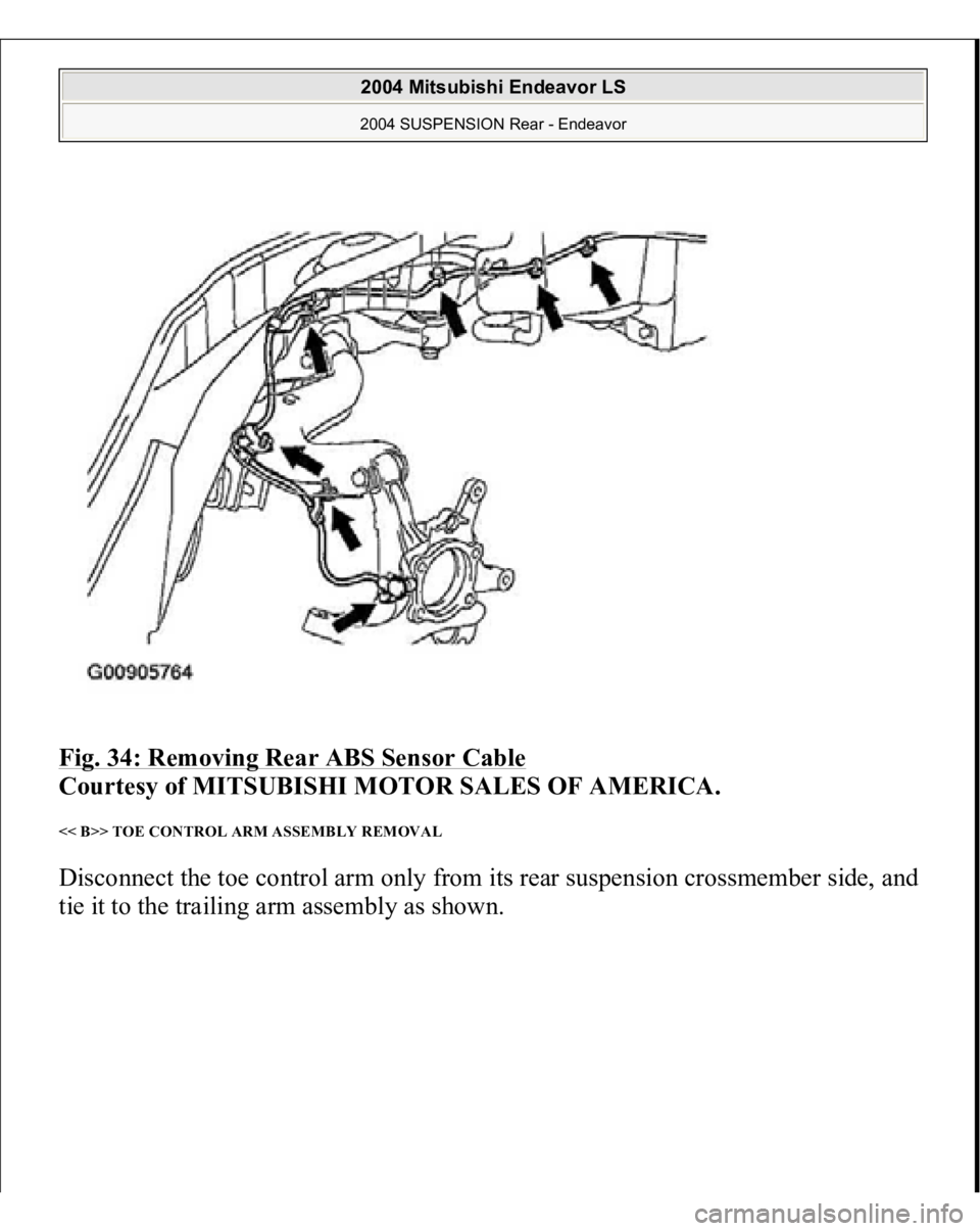
REMOVAL SERVICE POINTS << A>> REAR ABS SENSOR REMOVAL < VEHICLES WITH ABS> The rear ABS sensor can be damaged during service work. Unclamp the rear ABS
sensor cable as shown, and tie it out of the wa
y.
CAUTION: For vehicles with ABS, be careful when handling the
pole piece at the tip of the ABS sensor so as not to
damage it by striking against other parts.
2004 Mitsubishi Endeavor LS 2004 SUSPENSION Rear - Endeavor
Page 3076 of 3870
Fig. 34: Removing Rear ABS Sensor Cable
Courtesy of MITSUBISHI MOTOR SALES OF AMERICA.
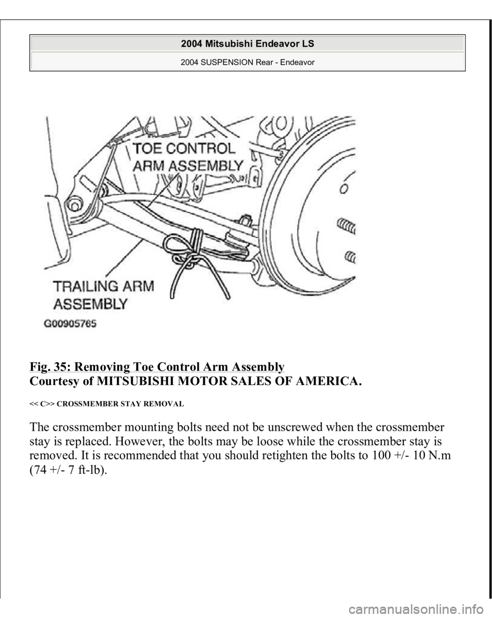
<< B>> TOE CONTROL ARM ASSEMBLY REMOVAL Disconnect the toe control arm only from its rear suspension crossmember side, and
tie it to the trailin
g arm assembl
y as shown.
2004 Mitsubishi Endeavor LS 2004 SUSPENSION Rear - Endeavor
Page 3077 of 3870
Fig. 35: Removing Toe Control Arm Assembly
Courtesy of MITSUBISHI MOTOR SALES OF AMERICA.
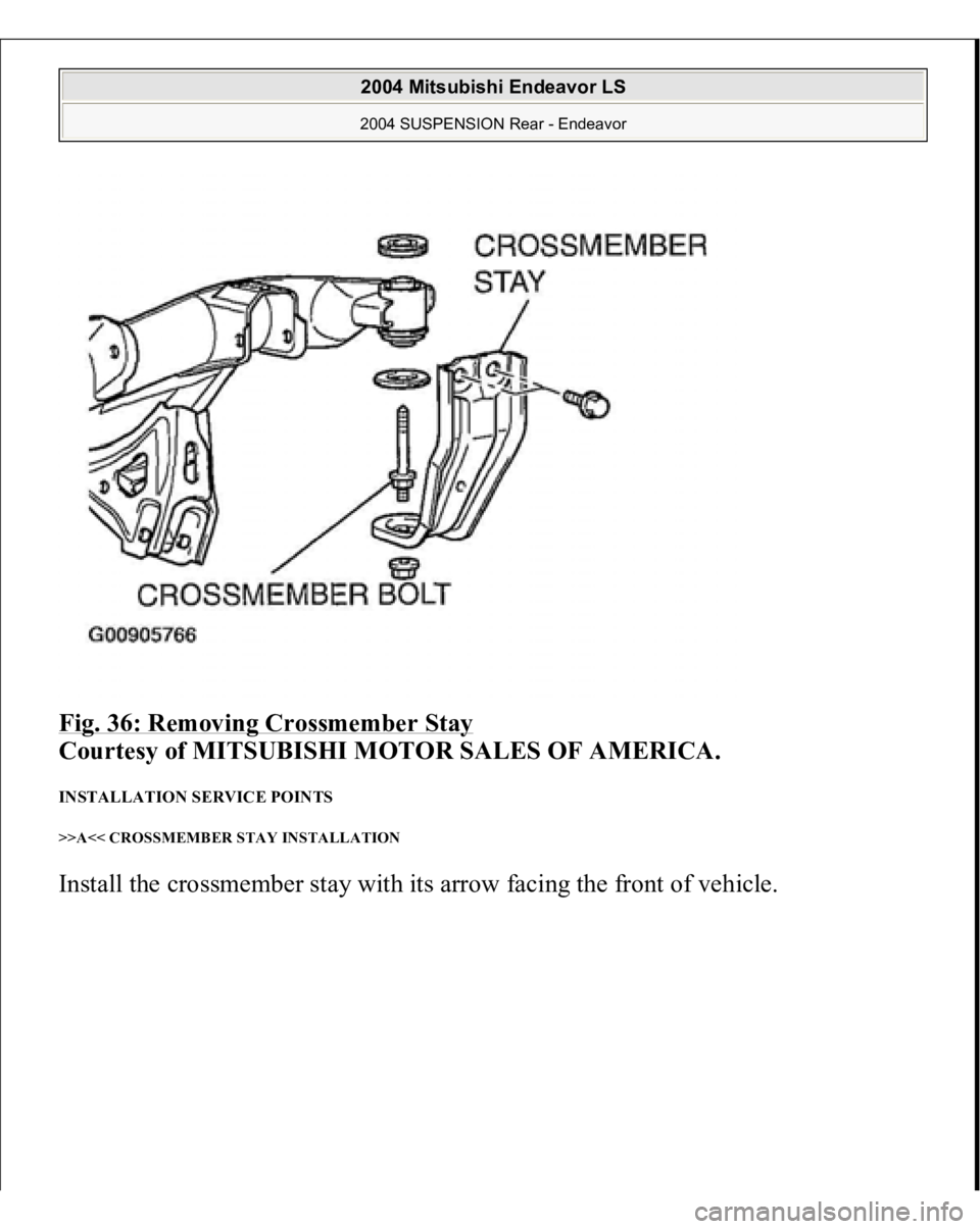
<< C>> CROSSMEMBER STAY REMOVAL The crossmember mounting bolts need not be unscrewed when the crossmember
stay is replaced. However, the bolts may be loose while the crossmember stay is
removed. It is recommended that you should retighten the bolts to 100 +/- 10 N.m (74 +
/- 7 f
t-lb
).
2004 Mitsubishi Endeavor LS 2004 SUSPENSION Rear - Endeavor
Page 3078 of 3870
Fig. 36: Removing Crossmember Stay
Courtesy of MITSUBISHI MOTOR SALES OF AMERICA.
INSTALLATION SERVICE POINTS >>A<< CROSSMEMBER STAY INSTALLATION Install the crossmember stay with its arrow facing the front of vehicle.
2004 Mitsubishi Endeavor LS 2004 SUSPENSION Rear - Endeavor
