MITSUBISHI ENDEAVOR 2004 Service Repair Manual
ENDEAVOR 2004
MITSUBISHI
MITSUBISHI
https://www.carmanualsonline.info/img/19/57105/w960_57105-0.png
MITSUBISHI ENDEAVOR 2004 Service Repair Manual
Page 1096 of 3870
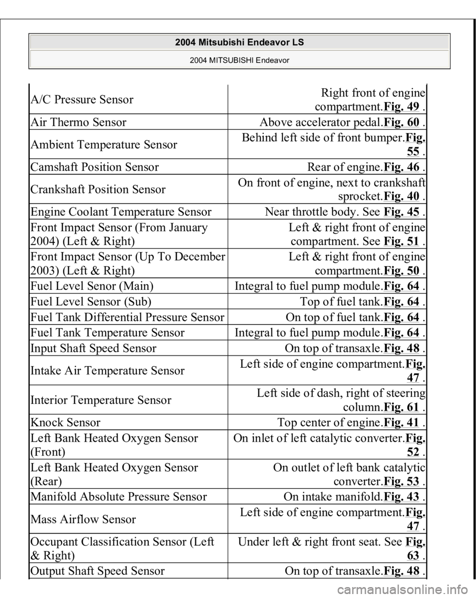
A/C Pressure Sensor
Right front of engine
compartment.Fig. 49
.
Air Thermo Sensor
Above accelerator pedal.Fig. 60
.
Ambient Temperature Sensor
Behind left side of front bumper.Fig.
55 .
Camshaft Position Sensor
Rear of engine.Fig. 46
.
Crankshaft Position Sensor
On front of engine, next to crankshaft
sprocket.Fig. 40
.
Engine Coolant Temperature Sensor
Near throttle body. See Fig. 45
.
Front Impact Sensor (From January
2004) (Left & Right)
Left & right front of engine
compartment. See Fig. 51
.
Front Impact Sensor (Up To December
2003) (Left & Right)
Left & right front of engine
compartment.Fig. 50
.
Fuel Level Senor (Main)
Integral to fuel pump module.Fig. 64
.
Fuel Level Sensor (Sub)
Top of fuel tank.Fig. 64
.
Fuel Tank Differential Pressure Sensor
On top of fuel tank.Fig. 64
.
Fuel Tank Temperature Sensor
Integral to fuel pump module.Fig. 64
.
Input Shaft Speed Sensor
On top of transaxle.Fig. 48
.
Intake Air Temperature Sensor
Left side of engine compartment.Fi
g.
47 .
Interior Temperature Sensor
Left side of dash, right of steering
column.Fig. 61
.
Knock Sensor
Top center of engine.Fig. 41
.
Left Bank Heated Oxygen Sensor
(Front)
On inlet of left catalytic converter.Fi
g.
52 .
Left Bank Heated Oxygen Sensor
(Rear)
On outlet of left bank catalytic
converter.Fig. 53
.
Manifold Absolute Pressure Sensor
On intake manifold.Fig. 43
.
Mass Airflow Sensor
Left side of engine compartment.Fi
g.
47 .
Occupant Classification Sensor (Left
& Right)
Under left & right front seat. See Fi
g.
63 .
Output Shaft Speed Sensor
On top of transaxle.Fig. 48
.
2004 Mitsubishi Endeavor LS
2004 MITSUBISHI Endeavor
Page 1331 of 3870
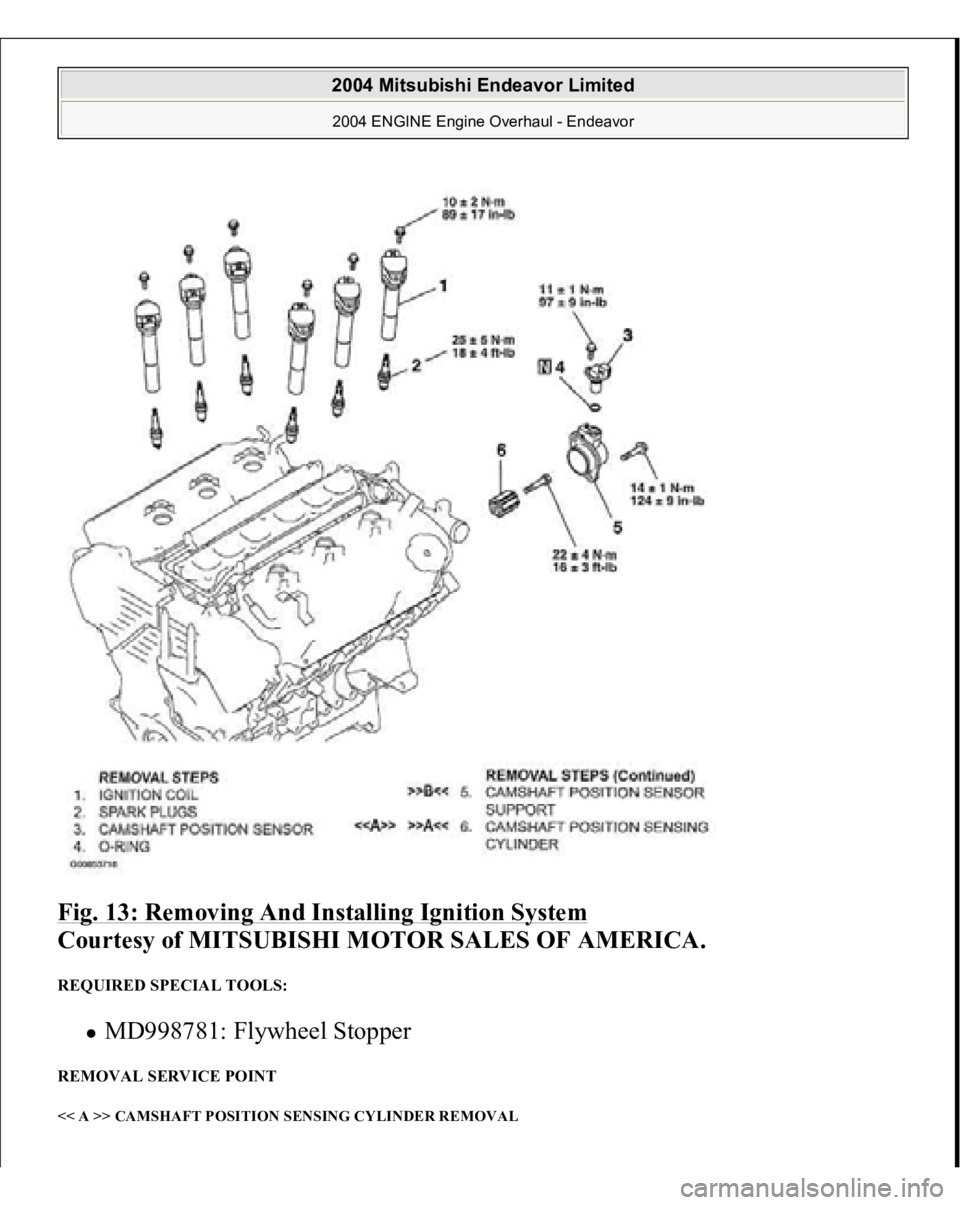
Fig. 13: Removing And Installing Ignition System
Courtesy of MITSUBISHI MOTOR SALES OF AMERICA.
REQUIRED SPECIAL TOOLS:
MD998781: Flywheel Stopper
REMOVAL SERVICE POINT << A >> CAMSHAFT POSITION SENSING CYLINDER REMOVAL
2004 Mitsubishi Endeavor Limited 2004 ENGINE Engine Overhaul - Endeavor
Page 1332 of 3870
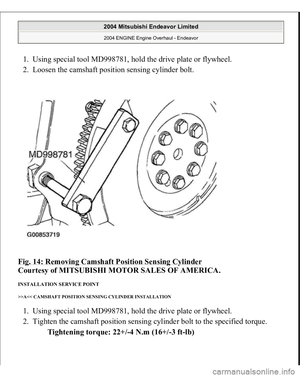
1. Using special tool MD998781, hold the drive plate or flywheel.
2. Loosen the camshaft position sensing cylinder bolt.
Fig. 14: Removing Camshaft Position Sensing Cylinder
Courtesy of MITSUBISHI MOTOR SALES OF AMERICA.
INSTALLATION SERVICE POINT >>A<< CAMSHAFT POSITION SENSING CYLINDER INSTALLATION 1. Using special tool MD998781, hold the drive plate or flywheel.
2. Tighten the camshaft position sensing cylinder bolt to the specified torque.
Tightening torque: 22+/-4 N.m (16+/-3 ft-lb)
2004 Mitsubishi Endeavor Limited 2004 ENGINE Engine Overhaul - Endeavor
Page 1333 of 3870
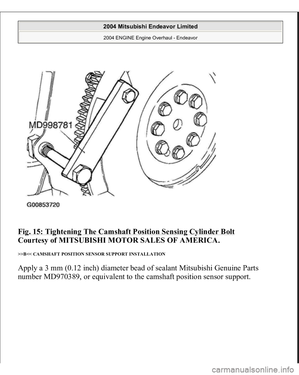
Fig. 15: Tightening The Camshaft Position Sensing Cylinder Bolt
Courtesy of MITSUBISHI MOTOR SALES OF AMERICA.
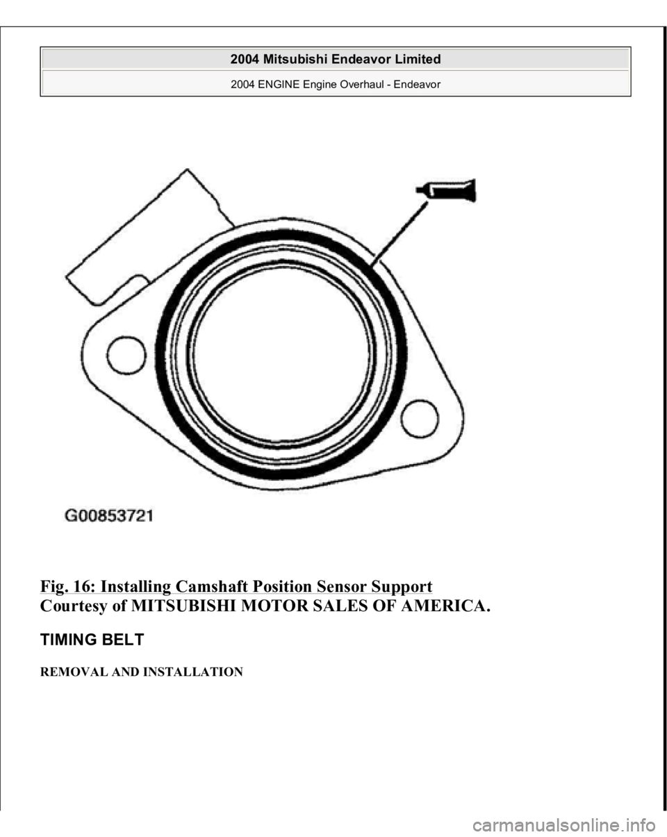
>>B<< CAMSHAFT POSITION SENSOR SUPPORT INSTALLATION Apply a 3 mm (0.12 inch) diameter bead of sealant Mitsubishi Genuine Parts
number MD970389, or e
quivalent to the camshaft
position sensor su
pport.
2004 Mitsubishi Endeavor Limited 2004 ENGINE Engine Overhaul - Endeavor
Page 1334 of 3870
Fig. 16: Installing Camshaft Position Sensor Support
Courtesy of MITSUBISHI MOTOR SALES OF AMERICA.
TIMING BELT REMOVAL AND INSTALLATION
2004 Mitsubishi Endeavor Limited 2004 ENGINE Engine Overhaul - Endeavor
Page 1336 of 3870
MD998715: Pins MD998767: Tensioner Pulley Wrench MD998769: Crankshaft Spacer
REMOVAL SERVICE POINTS << A >> TIMING BELT REMOVAL 1. Mark the belt running direction for reinstallation.
2. Loosen the tensioner pulley bolt, and then remove
the timing belt.
CAUTION: Water or oil on the belt shortens its life drasticall
y, so
the removed timing belt, sprocket, and tensioner
must be kept free from oil and water. These parts
should not be washed or immersed in solvent.
Replace parts if contaminated. If there is oil or water
on any part, check the front case oil seal, camshaft
oil seal, and water pump for leaks.
2004 Mitsubishi Endeavor Limited 2004 ENGINE Engine Overhaul - Endeavor
Page 1337 of 3870
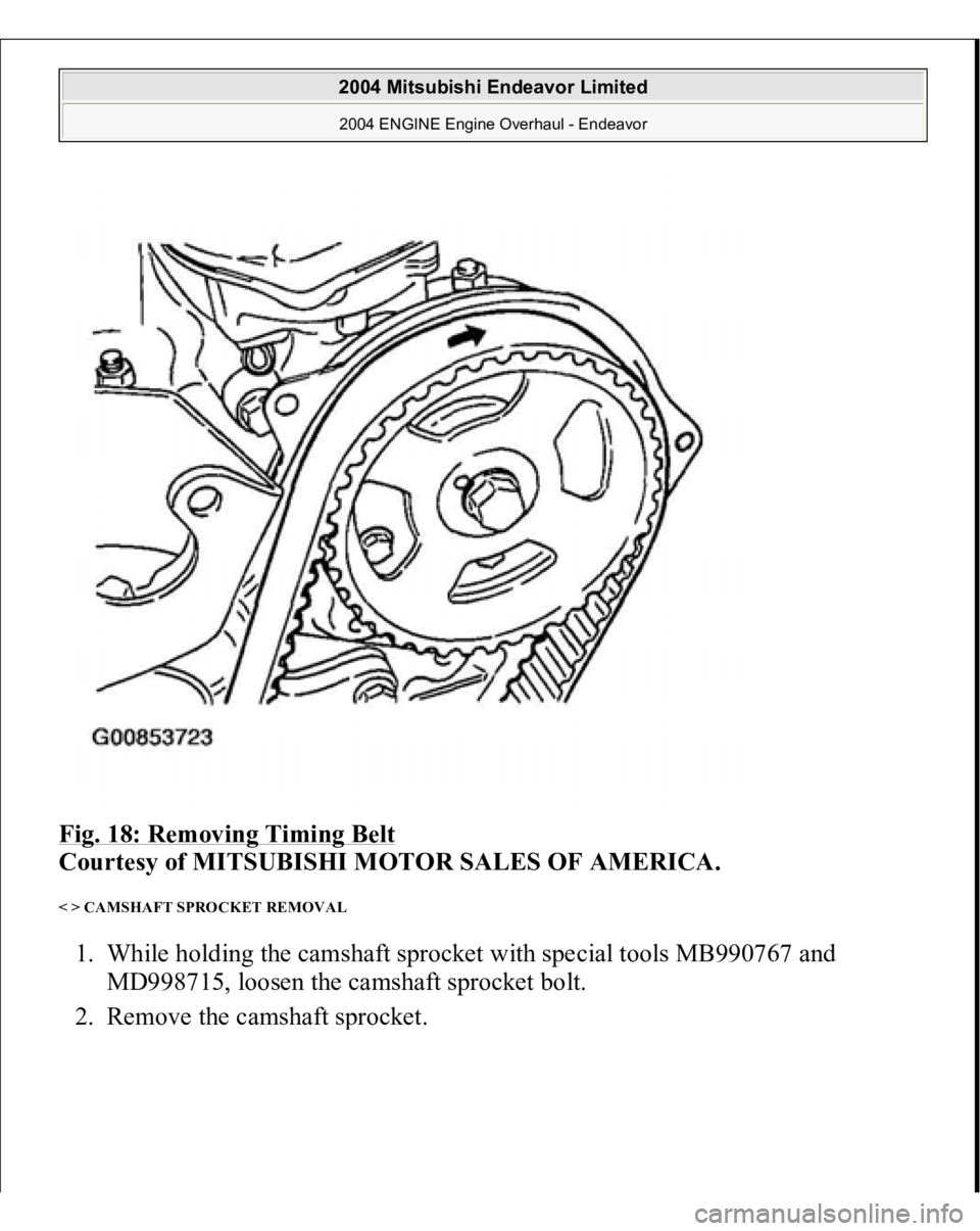
Fig. 18: Removing Timing Belt
Courtesy of MITSUBISHI MOTOR SALES OF AMERICA.
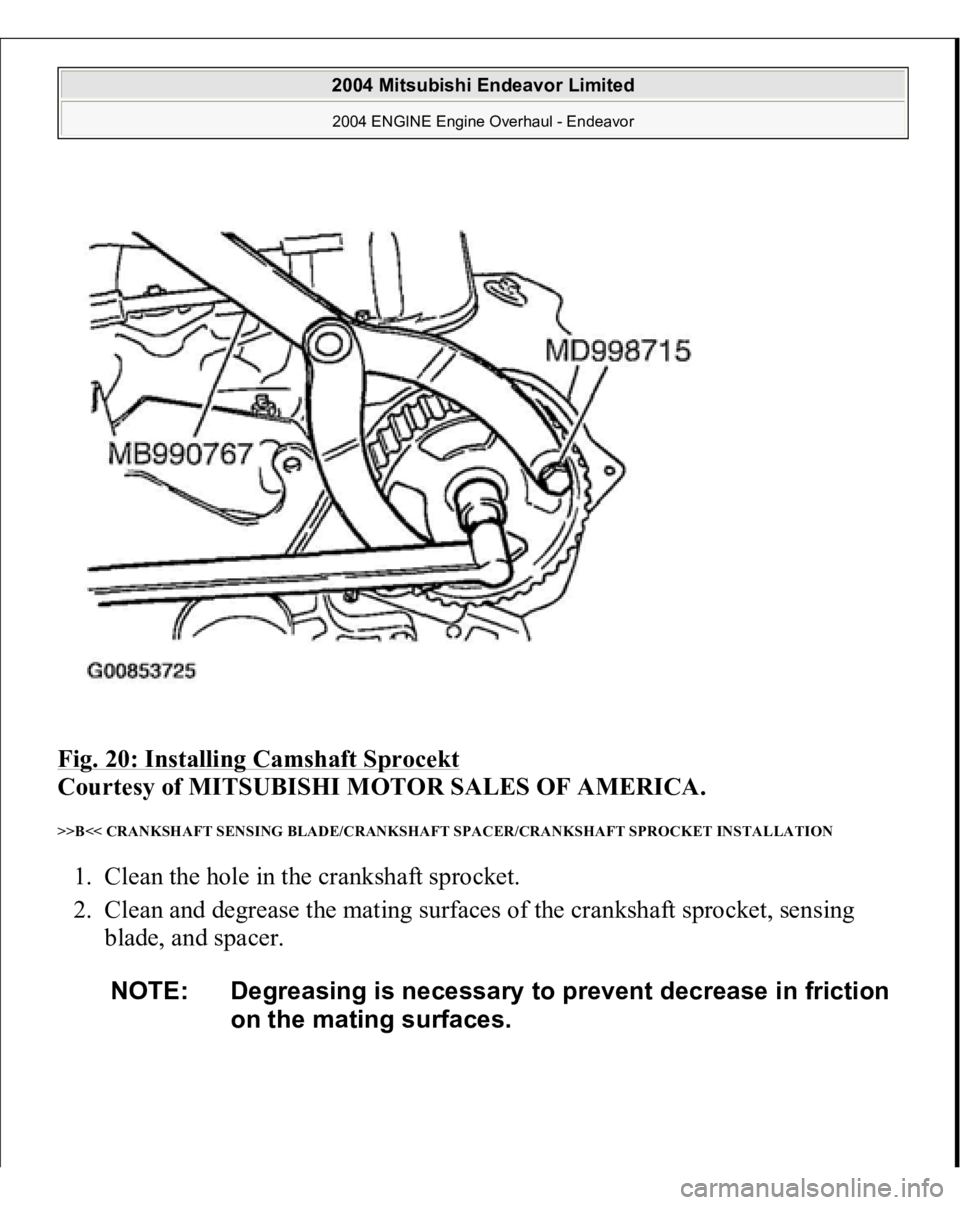
< > CAMSHAFT SPROCKET REMOVAL 1. While holding the camshaft sprocket with special tools MB990767 and
MD998715, loosen the camshaft sprocket bolt.
2. Remove the camshaft s
procket.
2004 Mitsubishi Endeavor Limited 2004 ENGINE Engine Overhaul - Endeavor
Page 1338 of 3870
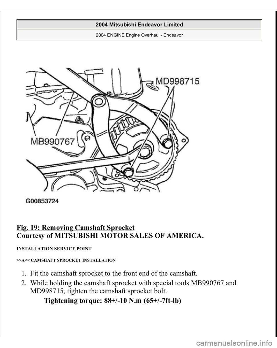
Fig. 19: Removing Camshaft Sprocket
Courtesy of MITSUBISHI MOTOR SALES OF AMERICA.
INSTALLATION SERVICE POINT >>A<< CAMSHAFT SPROCKET INSTALLATION 1. Fit the camshaft sprocket to the front end of the camshaft.
2. While holding the camshaft sprocket with special tools MB990767 and
MD998715, tighten the camshaft sprocket bolt.
Tightening torque: 88+/-10 N.m (65+/-7ft-lb)
2004 Mitsubishi Endeavor Limited 2004 ENGINE Engine Overhaul - Endeavor
Page 1339 of 3870
Fig. 20: Installing Camshaft Sprocekt
Courtesy of MITSUBISHI MOTOR SALES OF AMERICA.
>>B<< CRANKSHAFT SENSING BLADE/CRANKSHAFT SPACER/CRANKSHAFT SPROCKET INSTALLATION 1. Clean the hole in the crankshaft sprocket.
2. Clean and degrease the mating surfaces of the crankshaft sprocket, sensing
blade, and spacer.
NOTE: Degreasing is necessary to prevent decrease in friction
on the mating surfaces.
2004 Mitsubishi Endeavor Limited 2004 ENGINE Engine Overhaul - Endeavor
Page 1342 of 3870
with hole B in the cylinder.
Fig. 23: Installing Auto
-Tensioner
Courtesy of MITSUBISHI MOTOR SALES OF AMERICA.
3. Insert a wire [1.4 mm (0.055 inch) in diameter] into the set holes. This auto-
tensioner setting wire will be used during timing belt alignment.
4. Unclamp the auto-tensioner from the vise.
>>D<< TIMING BELT INSTALLATION
CAUTION: Do not turn the camshaft when the piston in No. 1
cylinder is at top dead center on the compression
stroke. Doing so can cause the lifted valve to hit
against the piston, damaging parts.
2004 Mitsubishi Endeavor Limited 2004 ENGINE Engine Overhaul - Endeavor

![MITSUBISHI ENDEAVOR 2004 Service Repair Manual with hole B in the cylinder.
Fig. 23: Installing Auto
-Tensioner
Courtesy of MITSUBISHI MOTOR SALES OF AMERICA.
3. Insert a wire [1.4 mm (0.055 inch) in diameter] into the set holes. This auto-
t MITSUBISHI ENDEAVOR 2004 Service Repair Manual with hole B in the cylinder.
Fig. 23: Installing Auto
-Tensioner
Courtesy of MITSUBISHI MOTOR SALES OF AMERICA.
3. Insert a wire [1.4 mm (0.055 inch) in diameter] into the set holes. This auto-
t](/img/19/57105/w960_57105-1341.png)