power control MITSUBISHI ENDEAVOR 2004 Service Repair Manual
[x] Cancel search | Manufacturer: MITSUBISHI, Model Year: 2004, Model line: ENDEAVOR, Model: MITSUBISHI ENDEAVOR 2004Pages: 3870, PDF Size: 98.47 MB
Page 309 of 3870
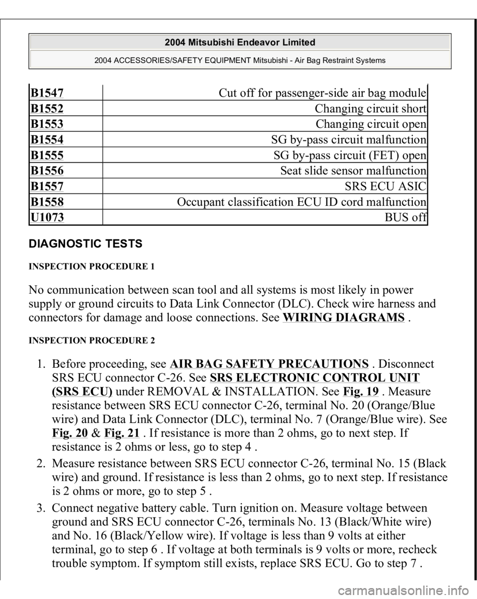
DIAGNOSTIC TESTS INSPECTION PROCEDURE 1 No communication between scan tool and all systems is most likely in power
supply or ground circuits to Data Link Connector (DLC). Check wire harness and
connectors for damage and loose connections. See WIRING DIAGRAMS
.
INSPECTION PROCEDURE 2 1. Before proceeding, see AIR BAG SAFETY PRECAUTIONS
. Disconnect
SRS ECU connector C-26. See SRS ELECTRONIC CONTROL UNIT
(SRS ECU)
under REMOVAL & INSTALLATION. See Fig. 19
. Measure
resistance between SRS ECU connector C-26, terminal No. 20 (Orange/Blue
wire) and Data Link Connector (DLC), terminal No. 7 (Orange/Blue wire). See
Fig. 20
& Fig. 21
. If resistance is more than 2 ohms, go to next step. If
resistance is 2 ohms or less, go to step 4 .
2. Measure resistance between SRS ECU connector C-26, terminal No. 15 (Black
wire) and ground. If resistance is less than 2 ohms, go to next step. If resistance
is 2 ohms or more, go to step 5 .
3. Connect negative battery cable. Turn ignition on. Measure voltage between
ground and SRS ECU connector C-26, terminals No. 13 (Black/White wire)
and No. 16 (Black/Yellow wire). If voltage is less than 9 volts at either
terminal, go to step 6 . If voltage at both terminals is 9 volts or more, recheck
trouble s
ymptom. If s
ymptom still exists, re
place SRS ECU. Go to ste
p 7 .
B1547
Cut off for passenger-side air bag module
B1552
Changing circuit short
B1553
Changing circuit open
B1554
SG by-pass circuit malfunction
B1555
SG by-pass circuit (FET) open
B1556
Seat slide sensor malfunction
B1557
SRS ECU ASIC
B1558
Occupant classification ECU ID cord malfunction
U1073
BUS of
f
2004 Mitsubishi Endeavor Limited
2004 ACCESSORIES/SAFETY EQUIPMENT Mitsubishi - Air Bag Restraint Systems
Page 326 of 3870
3. Reconnect all SRS components. Using scan tool, erase then retrieve DTCs. If
DTC 34 is retrieved, go to step 1 . If DTC 34 is not retrieved, system is normal
at this time. Intermittent condition may exist. DTC 35: SRS ECU AIR BAG DEPLOYMENT If DTC 35 is present, replace SRS ECU. See SRS ELECTRONIC CONTROL UNIT (SRS ECU)
under REMOVAL & INSTALLATION.
DTC 41: IG1 POWER CIRCUIT 1. Before proceeding, see AIR BAG SAFETY PRECAUTIONS
. Disable air
bag system. See DISABLING & ACTIVATING AIR BAG SYSTEM
.
Inspect fuse No. 23 in driver-side junction block, located on left side of
instrument panel. If fuse is okay, go to next step. If fuse is not okay, go to step
4 .
2. Disconnect negative battery cable. Disconnect SRS ECU connector C-26. See
SRS ELECTRONIC CONTROL UNIT (SRS ECU)
under REMOVAL &
INSTALLATION. See Fig. 19
. Connect negative battery cable. Turn ignition
on. Measure voltage between ground and SRS ECU connector C-26, terminal
No. 16 (Black/Yellow wire). See Fig. 21
. If voltage is less than 9 volts, go to
next step. If voltage is 9 volts or more, erase then retrieve DTCs using scan
tool. If DTC 41 is retrieved, replace SRS ECU. Go to step 10 .
3. Check wire harness between SRS ECU connector C-26, terminal No. 16 and
ignition switch connector C-308, terminal No. 2, including connectors C-211
and C-215. See Fig. 22
. If wire harness or connectors are damaged, replace
wire harness. Go to step 10 . If wire harness and connectors are okay, go to
step 10 .
4. Replace fuse. Turn ignition on for at least one minute, then off. Inspect fuse. If
fuse is okay, go to step 10 . If fuse is not okay, go to next step.
5. Disconnect connector C-211 from junction block. Check for continuity
between ground and connector C-211, terminal No. 24 (Black/Yellow wire).
See Fig. 26
. If continuity exists, go to next step. If continuity does not exist,
go to step 8 .
6. Check for continuity between ground and terminal No. 25 (Black/White wire)
of connector C-211. If continuit
y does not exist
, check other circuits associated
2004 Mitsubishi Endeavor Limited
2004 ACCESSORIES/SAFETY EQUIPMENT Mitsubishi - Air Bag Restraint Systems
Page 328 of 3870
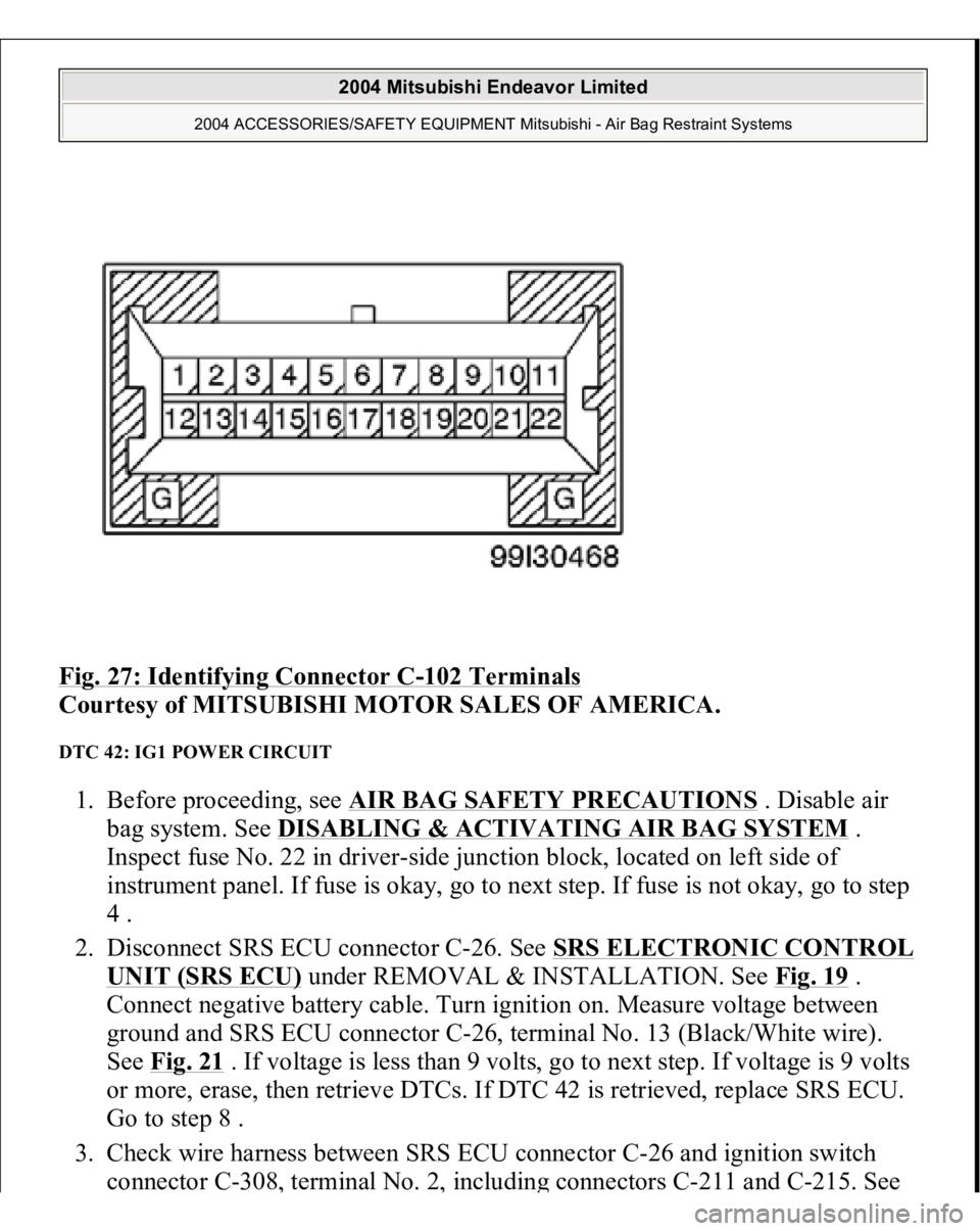
Fig. 27: Identifying Connector C
-102 Terminals
Courtesy of MITSUBISHI MOTOR SALES OF AMERICA.
DTC 42: IG1 POWER CIRCUIT 1. Before proceeding, see AIR BAG SAFETY PRECAUTIONS
. Disable air
bag system. See DISABLING & ACTIVATING AIR BAG SYSTEM
.
Inspect fuse No. 22 in driver-side junction block, located on left side of
instrument panel. If fuse is okay, go to next step. If fuse is not okay, go to step
4 .
2. Disconnect SRS ECU connector C-26. See SRS ELECTRONIC CONTROL
UNIT (SRS ECU)
under REMOVAL & INSTALLATION. See Fig. 19
.
Connect negative battery cable. Turn ignition on. Measure voltage between
ground and SRS ECU connector C-26, terminal No. 13 (Black/White wire).
See Fig. 21
. If voltage is less than 9 volts, go to next step. If voltage is 9 volts
or more, erase, then retrieve DTCs. If DTC 42 is retrieved, replace SRS ECU.
Go to step 8 .
3. Check wire harness between SRS ECU connector C-26 and ignition switch
connector C-308
, terminal No. 2
, includin
g connectors C-211 and C-215. See
2004 Mitsubishi Endeavor Limited
2004 ACCESSORIES/SAFETY EQUIPMENT Mitsubishi - Air Bag Restraint Systems
Page 344 of 3870
bag system. See DISABLING & ACTIVATING AIR BAG SYSTE
M . Go
to next step.
2. Replace passenger side impact sensor with driver side impact sensor. See
SIDE IMPACT SENSOR
under REMOVAL & INSTALLATION. Connect
negative battery cable. Using scan tool, erase then retrieve DTCs. If DTCs 89
or 96 are erased and DTCs 79 or 93 are retrieved, replace passenger side
impact sensor. If DTC 89 or 96 are not erased and DTC 79 or 93 are not
retrieved, go to next step.
3. Check wire harness between SRS ECU connector C-25 and passenger side
impact sensor connector D-18. See SRS ELECTRONIC CONTROL UNIT
(SRS ECU)
under REMOVAL & INSTALLATION. See Fig. 19
. Replace
wire harness, if damaged. Go to next step. If wire harness is okay, go to next
step.
4. Using scan tool, erase then retrieve DTCs. If DTC 89 or 96 is retrieved, replace
SRS ECU. If DTC 89 or 96 is not retrieved, system is normal at this time.
Intermittent condition may exist.
DTC 91: DRIVER SIDE IMPACT AIR BAG MODULE SENSOR POWER SUPPLY CIRCUIT 1. Before proceeding, see AIR BAG SAFETY PRECAUTIONS
. Disable air
bag system. See DISABLING & ACTIVATING AIR BAG SYSTEM
. Go
to next step.
2. Disconnect driver side impact sensor connector D-23. See SIDE IMPACT
SENSOR
under REMOVAL & INSTALLATION. See Fig. 19
. Connect
negative battery cable. Turn ignition on. Measure voltage between connector
D-24, terminal No. 2 (Black/Blue wire) and ground. See Fig. 29 . Turn ignition
off. If voltage is 9 volts or more, replace side impact sensor. If voltage is less
than 9 volts, go to next step.
3. Check wire harness between SRS ECU connector C-25 and driver side impact
sensor connector D-23 for an open or short circuit. If an open or short circuit is
found, replace wire harness. Go to next step. If wire harness is okay, go to next
step.
4. Reconnect all SRS components. Activate air bag system. Using scan tool, erase
then retrieve DTCs. If DTC 91 is retrieved, go to step 1 . If DTC 91 is not
retrieved, s
ystem is normal at this time. Intermit
tent condition ma
y exist.
2004 Mitsubishi Endeavor Limited
2004 ACCESSORIES/SAFETY EQUIPMENT Mitsubishi - Air Bag Restraint Systems
Page 345 of 3870
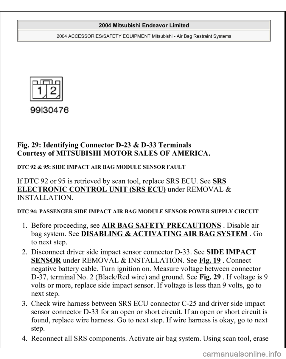
Fig. 29: Identifying Connector D
-23 & D
-33 Terminals
Courtesy of MITSUBISHI MOTOR SALES OF AMERICA.
DTC 92 & 95: SIDE IMPACT AIR BAG MODULE SENSOR FAULT If DTC 92 or 95 is retrieved by scan tool, replace SRS ECU. See SRS ELECTRONIC CONTROL UNIT (SRS ECU)
under REMOVAL &
INSTALLATION.
DTC 94: PASSENGER SIDE IMPACT AIR BAG MODULE SENSOR POWER SUPPLY CIRCUIT 1. Before proceeding, see AIR BAG SAFETY PRECAUTIONS
. Disable air
bag system. See DISABLING & ACTIVATING AIR BAG SYSTEM
. Go
to next step.
2. Disconnect driver side impact sensor connector D-33. See SIDE IMPACT
SENSOR
under REMOVAL & INSTALLATION. See Fig. 19
. Connect
negative battery cable. Turn ignition on. Measure voltage between connector
D-37, terminal No. 2 (Black/Red wire) and ground. See Fig. 29 . If voltage is 9
volts or more, replace side impact sensor. If voltage is less than 9 volts, go to
next step.
3. Check wire harness between SRS ECU connector C-25 and driver side impact
sensor connector D-33 for an open or short circuit. If an open or short circuit is
found, replace wire harness. Go to next step. If wire harness is okay, go to next
step.
4. Reconnect all SRS com
ponents. Activate air ba
g system. Usin
g scan tool, erase
2004 Mitsubishi Endeavor Limited
2004 ACCESSORIES/SAFETY EQUIPMENT Mitsubishi - Air Bag Restraint Systems
Page 346 of 3870
then retrieve DTCs. If DTC 94 is retrieved, go to step 1 . If DTC 94 is not
retrieved, system is normal at this time. Intermittent condition may exist.
DIAGNOSTIC TESTS (DUAL-STAGE AIR BAG SYSTEM) INSPECTION PROCEDURE 1 Connect scan tool to Data Link Connector (DLC). See INITIAL SRS DIAGNOSTIC PROCEDURE
under DIAGNOSTICS. Turn ignition on. If scan
tool is able to diagnose CAN bus lines and CAN bus lines are satisfactory, inspect
and repair power circuits. Go to INSPECTION PROCEDURE 2
. If scan tool
cannot diagnose CAN bus lines, inspect and repair CAN bus lines.
INSPECTION PROCEDURE 2 1. Connect scan tool to Data Link Connector (DLC). See INITIAL SRS
DIAGNOSTIC PROCEDURE
under DIAGNOSTICS. Disconnect SRS ECU
connector C-26. See SRS ELECTRONIC CONTROL UNIT (SRS ECU)
under REMOVAL & INSTALLATION. See Fig. 30
. Measure resistance
between ground and connector C-26, terminal No. 40 (Black wire). If
resistance is 2 ohms or less, go to next step. If resistance is more than 2 ohms,
repair wiring harness between SRS ECU and ground. See WIRE REPAIR
.
2. Inspect Black/White wire and Black/Yellow wire between connector C-26 and
ignition switch connector C-308, including junction block connectors C-211
and C-215. See Fig. 22
. If wires are okay, go to next step. If wires are not
okay, replace wire harness.
3. Inspect battery. If battery is in good condition, go to next step. If battery is not
in good condition, charge or replace battery as appropriate. Go to step 5 .
4. Inspect charging system. If charging system is okay, go to next step. If
charging system is not okay, repair charging system as appropriate. Go to next
step.
5. Retest SRS system. If scan tool can communicate with SRS ECU, an
intermittent condition may have existed. If scan tool cannot communicate with
NOTE: If scan tool cannot communicate with SRS ECU, CAN bus
line may be defective.
2004 Mitsubishi Endeavor Limited
2004 ACCESSORIES/SAFETY EQUIPMENT Mitsubishi - Air Bag Restraint Systems
Page 394 of 3870
1. Connect scan tool to Data Link Connector (DLC). See INITIAL SRS
DIAGNOSTIC PROCEDURE
under DIAGNOSTICS. If scan tool is able to
diagnose CAN bus lines and CAN bus lines are satisfactory, go to next step. If
scan tool cannot diagnose CAN bus lines, repair CAN bus lines. Go to next
step.
2. Erase, then retrieve DTCs. If DTC B1475 is retrieved, replace SRS ECU. See
SRS ELECTRONIC CONTROL UNIT (SRS ECU)
under REMOVAL &
INSTALLATION. If DTC B1475 is not retrieved, an intermittent condition
may exist.
DTCB1476: POWER SUPPLY VOLTAGE DROPS ABNORMALLY 1. Connect scan tool to Data Link Connector (DLC). See INITIAL SRS
DIAGNOSTIC PROCEDURE
under DIAGNOSTICS. If scan tool is able to
diagnose CAN bus lines and CAN bus lines are satisfactory, go to next step. If
scan tool cannot diagnose CAN bus lines, repair CAN bus lines. Go to next
step.
2. Erase, then retrieve DTCs. Turn ignition off. If DTC B1476 is retrieved, go to
next step. If DTC B1476 is not retrieved, an intermittent condition may exist.
3. Remove fuse No. 22 from instrument panel junction block. See Fig. 39
. If fuse
is blown, go to step 6 . If fuse is not blown, go to next step.
4. Disconnect negative battery cable. Disconnect SRS ECU connector C-26. See
SRS ELECTRONIC CONTROL UNIT (SRS ECU)
under REMOVAL &
INSTALLATION. See Fig. 30
. Connect negative battery cable. Turn ignition
on. Measure voltage between ground and SRS ECU connector C-26, terminal
No. 23 (Black/White wire). If voltage is 9 volts or more, reconnect SRS
components. Erase, then retrieve DTCs. If DTC B1476 is retrieved, replace
SRS ECU. Go to step 8 . If DTC B1476 is not retrieved, go to next step.
5. Inspect Black/White wire between SRS ECU connector C-26, terminal No. 23
and ignition switch connector C-308, terminal No. 2. If wire is okay, go to step
8 . If wire is not okay, replace harness between SRS ECU and ignition switch.
Go to step 8 .
6. Replace fuse. Turn ignition on for one minute, then turn off. Inspect fuse. If
fuse is okay, go to step 8 . If fuse is not okay, go to next step.
7. Measure resistance between SRS ECU connector C-26
, terminal No. 23 and
2004 Mitsubishi Endeavor Limited
2004 ACCESSORIES/SAFETY EQUIPMENT Mitsubishi - Air Bag Restraint Systems
Page 421 of 3870
REMOVAL & INSTALLATION. Measure resistance between SRS ECU
connector C-25, terminal No. 51 (Brown/Red wire) and No. 65 (Orange/Black
wire). See Fig. 33
. If resistance is 738-902 ohms, reconnect SRS components.
Erase, then retrieve DTCs. If DTC B1522 is retrieved, replace SRS ECU. Go to
step 6 . If DTC B1522 is not retrieved, go to next step.
5. Inspect wire harness between SRS ECU connector C-25 and passenger seat
belt buckle connector D-29 for damage. If wires are okay, go to next step. If
wires are not okay, replace wire harness. Go to next step.
6. Erase, then retrieve DTCs. If DTC B1522 is retrieved, go to step 1 . If DTC
B1522 is not retrieved, system is normal at this time.
DTC B1523: SEAT BELT SWITCH (RH) POWER-SIDE CIRCUIT SHORTED FOR N/C TERMINAL 1. Connect scan tool to Data Link Connector (DLC). See INITIAL SRS
DIAGNOSTIC PROCEDURE
under DIAGNOSTICS. If scan tool is able to
diagnose CAN bus lines and CAN bus lines are satisfactory, go to next step. If
scan tool cannot diagnose CAN bus lines, repair CAN bus lines. Go to next
step.
2. Erase, then retrieve DTCs. Turn ignition off. If DTC B1523 is retrieved, go to
next step. If DTC B1523 is not retrieved, an intermittent condition may exist.
3. Disconnect negative battery cable. Disconnect passenger-side seat belt buckle
connector D-39. See Fig. 30
. Latch seat belt into seat belt buckle. Measure
resistance between connector D-39, terminals No. 1 and 3. See Fig. 43
.
Resistance should be 800-840 ohms. Resistance between ground and terminal
No. 1 and 3 should be infinite. Unlatch seat belt buckle. Measure resistance
between terminal No. 2 and 3 of connector D-39. Resistance should be 800-
840 ohms. Resistance between ground and terminal No. 2 and 3 should be
infinite. If resistance is as specified, go to next step. If resistance is not as
specified, replace front seat belt buckle. Go to step 6 .
4. Reconnect seat belt buckle connector D-39. Disconnect SRS ECU connector
C-25. See SRS ELECTRONIC CONTROL UNIT (SRS ECU)
under
REMOVAL & INSTALLATION. Measure resistance between SRS ECU
connector C-25, terminal No. 51 (Brown/Red wire) and No. 65 (Orange/Black
wire). See Fig. 33
. If resistance is 738-902 ohms, reconnect SRS components.
Erase, then retrieve DTCs. If DTC B1523 is retrieved, re
place SRS ECU. Go to
2004 Mitsubishi Endeavor Limited
2004 ACCESSORIES/SAFETY EQUIPMENT Mitsubishi - Air Bag Restraint Systems
Page 423 of 3870
6. Erase, then retrieve DTCs. If DTC B1524 is retrieved, go to step 1 . If DTC
B1524 is not retrieved, system is normal at this time. DTC B1525: SEAT BELT SWITCH (RH) GROUND-SIDE CIRCUIT SHORTED FOR N/O
TERMINAL 1. Connect scan tool to Data Link Connector (DLC). See INITIAL SRS
DIAGNOSTIC PROCEDURE
under DIAGNOSTICS. If scan tool is able to
diagnose CAN bus lines and CAN bus lines are satisfactory, go to next step. If
scan tool cannot diagnose CAN bus lines, repair CAN bus lines. Go to next
step.
2. Erase, then retrieve DTCs. Turn ignition off. If DTC B1525 is retrieved, go to
next step. If DTC B1525 is not retrieved, an intermittent condition may exist.
3. Disconnect negative battery cable. Disconnect passenger-side seat belt buckle
connector D-39. See Fig. 30
. Latch seat belt into seat belt buckle. Measure
resistance between connector D-39, terminals No. 1 and 3. See Fig. 43
.
Resistance should be 800-840 ohms. Resistance between ground and terminal
No. 1 and 3 should be infinite. Unlatch seat belt buckle. Measure resistance
between terminal No. 2 and 3 of connector D-39. Resistance should be 800-
840 ohms. Resistance between ground and terminal No. 2 and 3 should be
infinite. If resistance is as specified, go to next step. If resistance is not as
specified, replace front seat belt buckle. Go to step 6 .
4. Reconnect seat belt buckle connector D-39. Disconnect SRS ECU connector
C-25. See SRS ELECTRONIC CONTROL UNIT (SRS ECU)
under
REMOVAL & INSTALLATION. Measure resistance between SRS ECU
connector C-25, terminal No. 51 (Brown/Red wire) and No. 65 (Orange/Black
wire). See Fig. 33
. If resistance is 738-902 ohms, reconnect SRS components.
Erase, then retrieve DTCs. If DTC B1525 is retrieved, replace SRS ECU. Go to
step 6 . If DTC B1525 is not retrieved, go to next step.
5. Inspect wire harness between SRS ECU connector C-25 and passenger seat
belt buckle connector D-29 for damage. If wires are okay, go to next step. If
wires are not okay, replace wire harness. Go to next step.
6. Erase, then retrieve DTCs. If DTC B1525 is retrieved, go to step 1 . If DTC
B1525 is not retrieved, system is normal at this time.
DTC B1526: SEAT BELT SWITCH (RH) POWER-SIDE CIRCUIT SHORTED FOR N/O TERMINAL
2004 Mitsubishi Endeavor Limited
2004 ACCESSORIES/SAFETY EQUIPMENT Mitsubishi - Air Bag Restraint Systems
Page 426 of 3870
3. Disconnect negative battery cable. Disconnect passenger-side seat belt buckle
connector D-39. See Fig. 30
. Latch seat belt into seat belt buckle. Measure
resistance between connector D-39, terminals No. 1 and 3. See Fig. 43
.
Resistance should be 800-840 ohms. Resistance between ground and terminal
No. 1 and 3 should be infinite. Unlatch seat belt buckle. Measure resistance
between terminal No. 2 and 3 of connector D-39. Resistance should be 800-
840 ohms. Resistance between ground and terminal No. 2 and 3 should be
infinite. If resistance is as specified, go to next step. If resistance is not as
specified, replace front seat belt buckle. Go to step 6 .
4. Reconnect seat belt buckle connector D-39. Disconnect SRS ECU connector
C-25. See SRS ELECTRONIC CONTROL UNIT (SRS ECU)
under
REMOVAL & INSTALLATION. Measure resistance between SRS ECU
connector C-25, terminal No. 51 (Brown/Red wire) and No. 65 (Orange/Black
wire). See Fig. 33
. If resistance is 738-902 ohms, reconnect SRS components.
Erase, then retrieve DTCs. If DTC B1528 is retrieved, replace SRS ECU. Go to
step 6 . If DTC B1528 is not retrieved, go to next step.
5. Inspect wire harness between SRS ECU connector C-25 and passenger seat
belt buckle connector D-29 for damage. If wires are okay, go to next step. If
wires are not okay, replace wire harness. Go to next step.
6. Erase, then retrieve DTCs. If DTC B1528 is retrieved, go to step 1 . If DTC
B1528 is not retrieved, system is normal at this time.
DTCB1529: SEAT BELT SWITCH (RH) POWER-SIDE CIRCUIT SHORTED FOR COM TERMINAL1. Connect scan tool to Data Link Connector (DLC). See INITIAL SRS
DIAGNOSTIC PROCEDURE
under DIAGNOSTICS. If scan tool is able to
diagnose CAN bus lines and CAN bus lines are satisfactory, go to next step. If
scan tool cannot diagnose CAN bus lines, repair CAN bus lines. Go to next
step.
2. Erase, then retrieve DTCs. Turn ignition off. If DTC B1529 is retrieved, go to
next step. If DTC B1529 is not retrieved, an intermittent condition may exist.
3. Disconnect negative battery cable. Disconnect passenger-side seat belt buckle
connector D-39. See Fig. 30
. Latch seat belt into seat belt buckle. Measure
resistance between connector D-39, terminals No. 1 and 3. See Fig. 43
.
Resistance should be 80
0-840 ohms. Resistance between
ground and terminal
2004 Mitsubishi Endeavor Limited
2004 ACCESSORIES/SAFETY EQUIPMENT Mitsubishi - Air Bag Restraint Systems