relay MITSUBISHI ENDEAVOR 2004 Service Repair Manual
[x] Cancel search | Manufacturer: MITSUBISHI, Model Year: 2004, Model line: ENDEAVOR, Model: MITSUBISHI ENDEAVOR 2004Pages: 3870, PDF Size: 98.47 MB
Page 90 of 3870
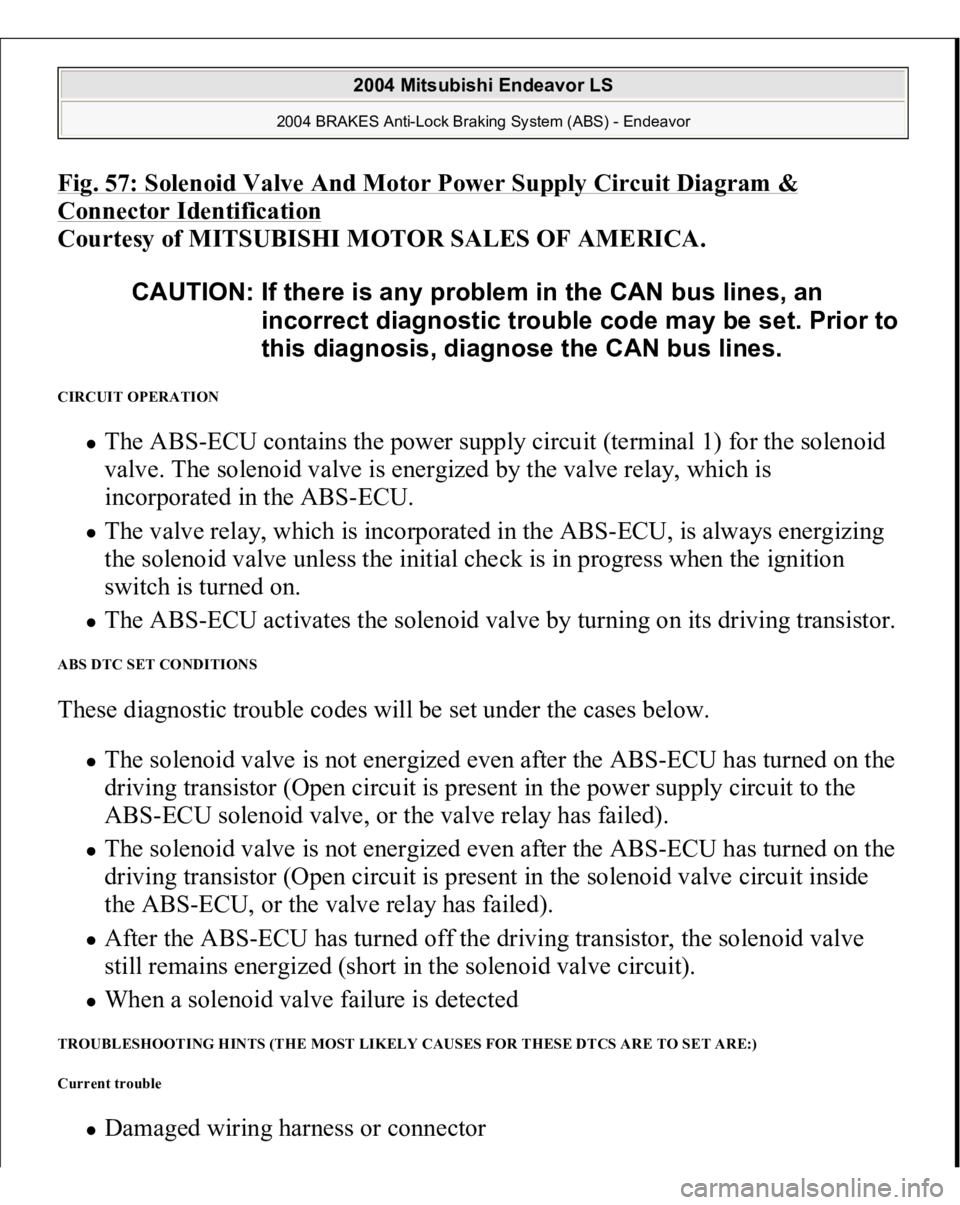
Fig. 57: Solenoid Valve And Motor Power Supply Circuit Diagram & Connector Identification
Courtesy of MITSUBISHI MOTOR SALES OF AMERICA.
CIRCUIT OPERATION
The ABS-ECU contains the power supply circuit (terminal 1) for the solenoid
valve. The solenoid valve is energized by the valve relay, which is
incorporated in the ABS-ECU. The valve relay, which is incorporated in the ABS-ECU, is always energizing
the solenoid valve unless the initial check is in progress when the ignition
switch is turned on. The ABS-ECU activates the solenoid valve by turning on its driving transistor.
ABS DTC SET CONDITIONS These diagnostic trouble codes will be set under the cases below.
The solenoid valve is not energized even after the ABS-ECU has turned on the
driving transistor (Open circuit is present in the power supply circuit to the
ABS-ECU solenoid valve, or the valve relay has failed). The solenoid valve is not energized even after the ABS-ECU has turned on the
driving transistor (Open circuit is present in the solenoid valve circuit inside
the ABS-ECU, or the valve relay has failed). After the ABS-ECU has turned off the driving transistor, the solenoid valve
still remains energized (short in the solenoid valve circuit). When a solenoid valve failure is detected
TROUBLESHOOTING HINTS (THE MOST LIKELY CAUSES FOR THESE DTCS ARE TO SET ARE:)
Current trouble
Dama
ged wirin
g harness or connector CAUTION: If there is any problem in the CAN bus lines, an
incorrect diagnostic trouble code may be set. Prior to
this diagnosis, diagnose the CAN bus lines.
2004 Mitsubishi Endeavor LS
2004 BRAKES Anti-Lock Braking System (ABS) - Endeavor
Page 108 of 3870
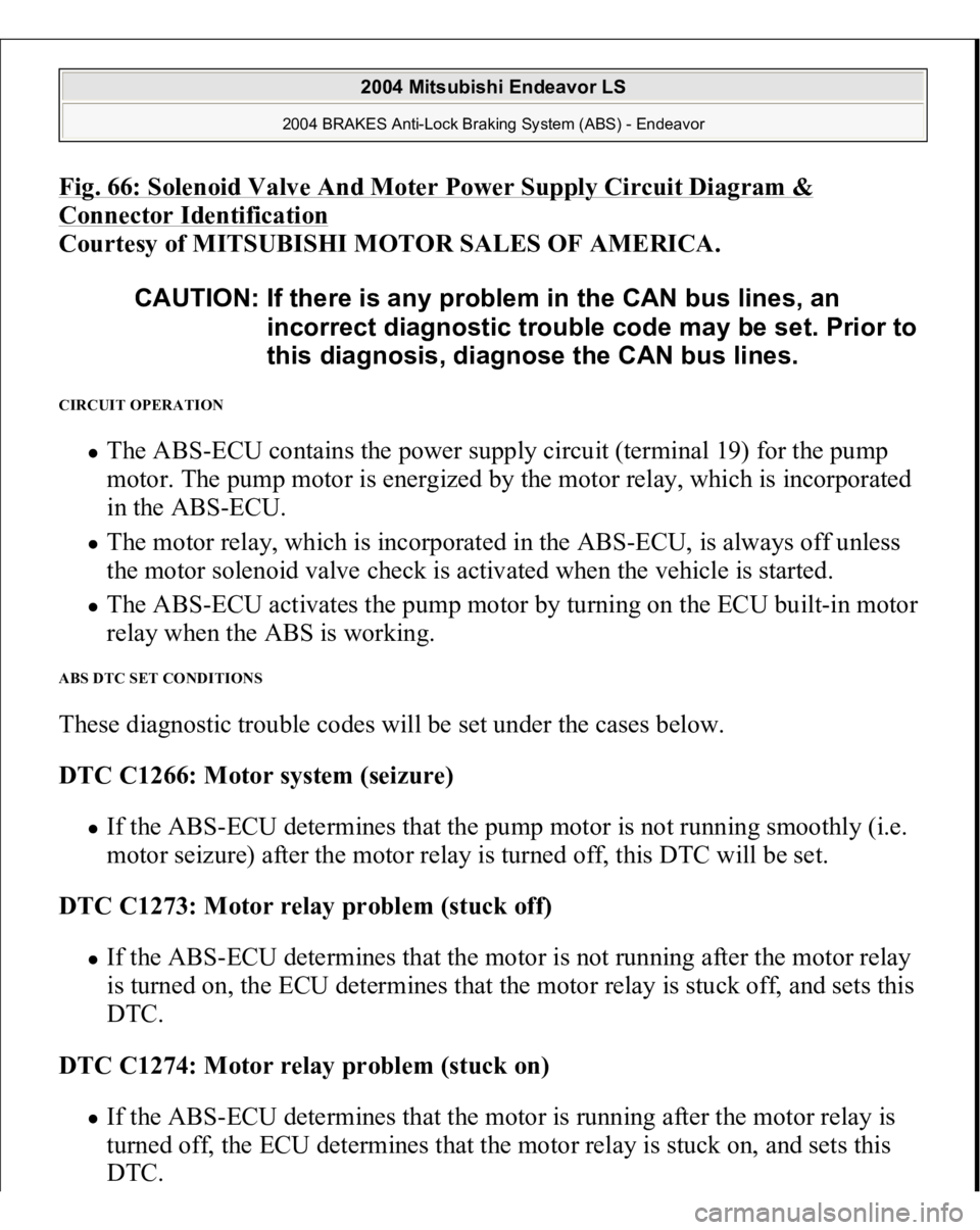
Fig. 66: Solenoid Valve And Moter Power Supply Circuit Diagram & Connector Identification
Courtesy of MITSUBISHI MOTOR SALES OF AMERICA.
CIRCUIT OPERATION
The ABS-ECU contains the power supply circuit (terminal 19) for the pump
motor. The pump motor is energized by the motor relay, which is incorporated
in the ABS-ECU. The motor relay, which is incorporated in the ABS-ECU, is always off unless
the motor solenoid valve check is activated when the vehicle is started. The ABS-ECU activates the pump motor by turning on the ECU built-in motor
relay when the ABS is working.
ABS DTC SET CONDITIONS These diagnostic trouble codes will be set under the cases below.
DTC C1266: Motor system (seizure)
If the ABS-ECU determines that the pump motor is not running smoothly (i.e.
motor seizure) after the motor relay is turned off, this DTC will be set.
DTC C1273: Motor relay problem (stuck off) If the ABS-ECU determines that the motor is not running after the motor relay
is turned on, the ECU determines that the motor relay is stuck off, and sets this
DTC.
DTC C1274: Motor relay problem (stuck on) If the ABS-ECU determines that the motor is running after the motor relay is
turned off, the ECU determines that the motor relay is stuck on, and sets this
DTC. CAUTION: If there is any problem in the CAN bus lines, an
incorrect diagnostic trouble code may be set. Prior to
this diagnosis, diagnose the CAN bus lines.
2004 Mitsubishi Endeavor LS
2004 BRAKES Anti-Lock Braking System (ABS) - Endeavor
Page 126 of 3870
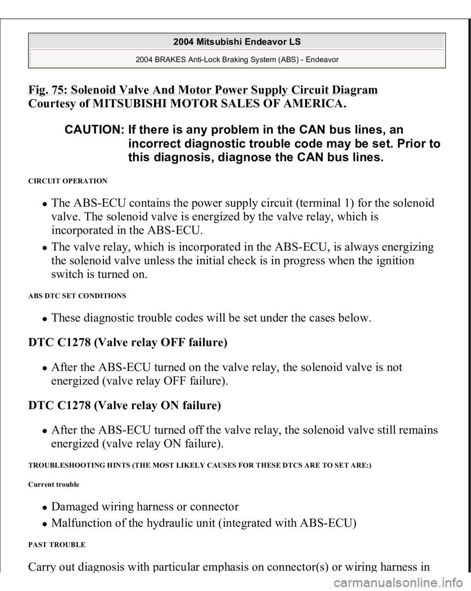
Fig. 75: Solenoid Valve And Motor Power Supply Circuit Diagra
m
Courtesy of MITSUBISHI MOTOR SALES OF AMERICA.
CIRCUIT OPERATION
The ABS-ECU contains the power supply circuit (terminal 1) for the solenoid
valve. The solenoid valve is energized by the valve relay, which is
incorporated in the ABS-ECU. The valve relay, which is incorporated in the ABS-ECU, is always energizing
the solenoid valve unless the initial check is in progress when the ignition
switch is turned on.
ABS DTC SET CONDITIONS
These diagnostic trouble codes will be set under the cases below.
DTC C1278 (Valve relay OFF failure) After the ABS-ECU turned on the valve relay, the solenoid valve is not
energized (valve relay OFF failure).
DTC C1278 (Valve relay ON failure) After the ABS-ECU turned off the valve relay, the solenoid valve still remains
energized (valve relay ON failure).
TROUBLESHOOTING HINTS (THE MOST LIKELY CAUSES FOR THESE DTCS ARE TO SET ARE:)
Current trouble
Damaged wiring harness or connector Malfunction of the hydraulic unit (integrated with ABS-ECU)
PAST TROUBLE Carr
y out dia
gnosis with
particular em
phasis on connector
(s) or wirin
g harness in CAUTION: If there is any problem in the CAN bus lines, an
incorrect diagnostic trouble code may be set. Prior to
this diagnosis, diagnose the CAN bus lines.
2004 Mitsubishi Endeavor LS
2004 BRAKES Anti-Lock Braking System (ABS) - Endeavor
Page 792 of 3870
2004 ENGINE COOLING
Electric Cooling Fans - Endeavor
DESCRIPTION & OPERATION The fan control module is powered from fusible link No. 2. See Fig. 1
. The PCM
judges the required revolution speed of radiator fan motor and condenser fan motor
using input signals transmitted from the A/C switch, automatic compressor
controller, vehicle speed sensor and engine coolant temperature sensor. The PCM
activates the fan control module to drive the radiator fan motor and condenser fan
motor. COMPONENT LOCATIONS COMPONENT LOCATIONS Component
Location
Condenser Fan
(1) Behind Radiator
Fan Control Module
(1) Integrated With Radiator Fan Motor
Fan Control Relay
In Engine Compartment Fuse/Relay
Box
Fusible Link No. 2
(2) In Engine Compartment Fuse/Relay
Box
Multi-Port Fuel Injection (MFI) Relay
In Engine Compartment Fuse/Relay
Box
Radiator Fan
(1) Behind Radiator
(1)
See Fig. 13
.
(2)
See Fig. 1
.
2004 Mitsubishi Endeavor Limited
2004 ENGINE COOLING Electric Cooling Fans - Endeavor
2004 Mitsubishi Endeavor Limited
2004 ENGINE COOLING Electric Cooling Fans - Endeavor
Page 796 of 3870
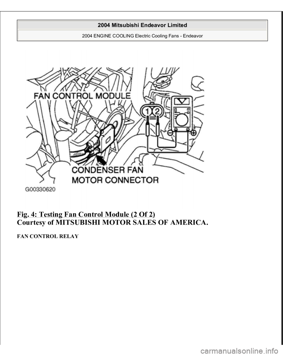
Fig. 4: Testing Fan Control Module (2 Of 2)
Courtesy of MITSUBISHI MOTOR SALES OF AMERICA.
FAN CONTROL RELAY
2004 Mitsubishi Endeavor Limited
2004 ENGINE COOLING Electric Cooling Fans - Endeavor
Page 797 of 3870
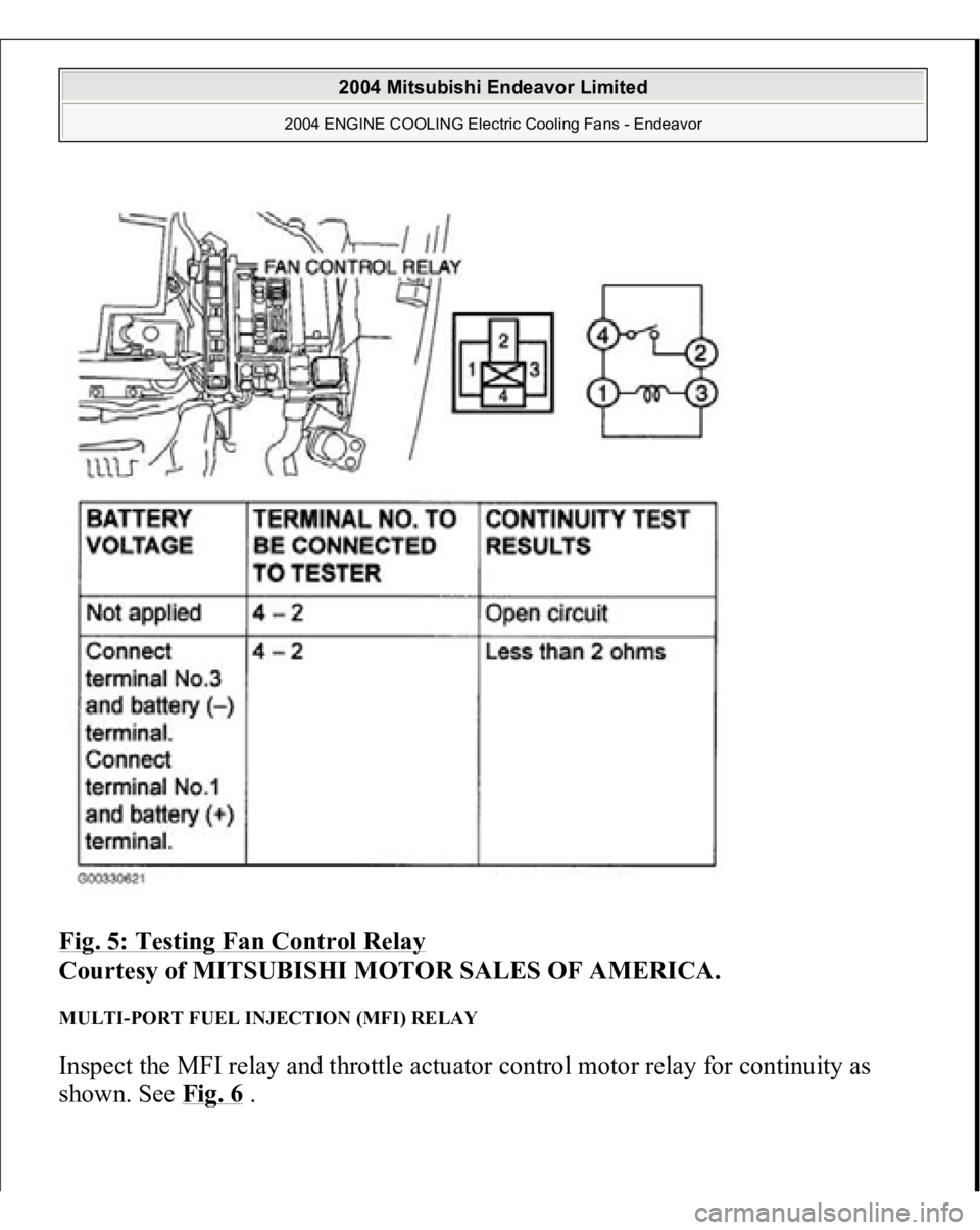
Fig. 5: Testing Fan Control Relay
Courtesy of MITSUBISHI MOTOR SALES OF AMERICA.
MULTI-PORT FUEL INJECTION (MFI) RELAY Inspect the MFI relay and throttle actuator control motor relay for continuity as
shown. See Fi
g. 6 .
2004 Mitsubishi Endeavor Limited
2004 ENGINE COOLING Electric Cooling Fans - Endeavor
Page 798 of 3870
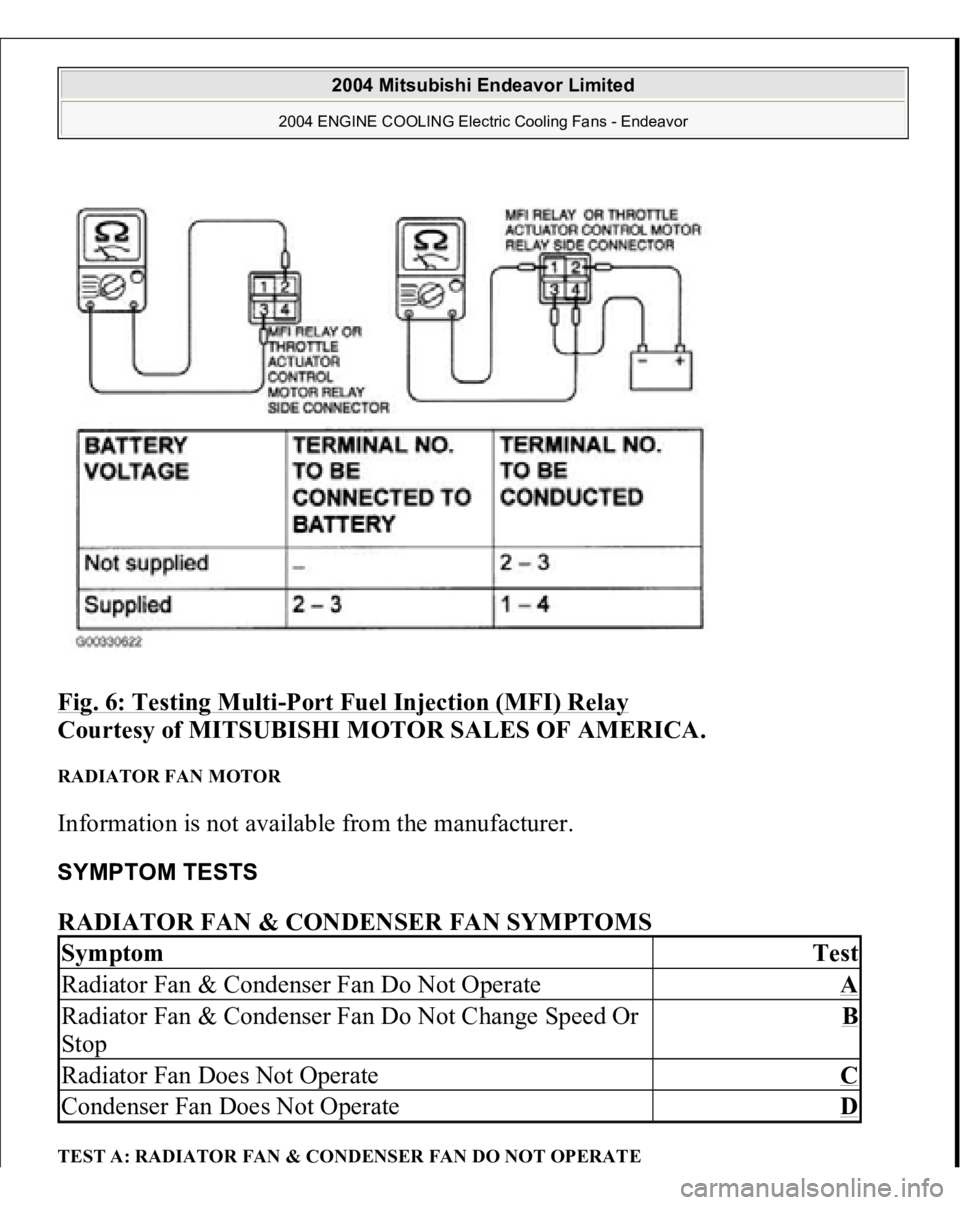
Fig. 6: Testing Multi
-Port Fuel Injection (MFI) Relay
Courtesy of MITSUBISHI MOTOR SALES OF AMERICA.
RADIATOR FAN MOTOR Information is not available from the manufacturer. SYMPTOM TESTS RADIATOR FAN & CONDENSER FAN SYMPTOMS TEST A: RADIATOR FAN & CONDENSER FAN DO NOT OPERATESymptom
Test
Radiator Fan & Condenser Fan Do Not Operate
A
Radiator Fan & Condenser Fan Do Not Change Speed Or
Stop
B
Radiator Fan Does Not Operate
C
Condenser Fan Does Not Operate
D
2004 Mitsubishi Endeavor Limited
2004 ENGINE COOLING Electric Cooling Fans - Endeavor
Page 799 of 3870
Technical Descriptio
n
The cause could be a malfunction of the fan control module power supply or
ground circuit. The cause could also be a malfunction of the fan control module or the PCM.
Troubleshooting Hints
Malfunction of fusible link. Malfunction of fan control relay. Malfunction of MFI relay. Malfunction of radiator fan motor. Malfunction of condenser fan motor. Malfunction of fan control module. Malfunction of PCM. Damaged wiring harness or connector.
Diagnosis 1. Disconnect fan control module connector A-23. See Fig. 7
. Measure for
voltage between terminal No. 3 (harness side of the connector) and ground
when ignition switch is turned to the ON position. If battery voltage is not
achieved, go to next step. If battery voltage is achieved, go to step 8 .
2. Check fan control relay. See FAN CONTROL RELAY under
COMPONENTS TESTS. If fan control relay is okay, go to next step. If fan
control relay is not okay, replace it and retest.
3. Check the MFI relay. See MULTI
-PORT FUEL INJECTION (MFI)
RELAY
under COMPONENT TESTS. If MFI relay is okay, go to next step. If
MFI relay is not okay, replace it and retest.
4. Check for harness damage in Black/Yellow wire between fusible link No. 2
and terminal No. 4 of fan control relay connector A-10X. See Fig. 8
. If wire is
okay, go to next step. If wire is damaged, repair or replace as necessary and
retest.
5. Check for harness damage in Blue wire between terminal No. 2 of fan control
rela
y connector
A-10X and terminal No. 3 of fan control module connector A-
2004 Mitsubishi Endeavor Limited
2004 ENGINE COOLING Electric Cooling Fans - Endeavor
Page 800 of 3870
23. See Fig. 7
and Fig.
8 . If wire is okay, go to next step. If wire is damaged,
repair or replace as necessary and retest.
6. Check intermediate connector A-13 for loose, corroded, or damaged terminals,
or terminals pushed back in the connector. See Fig. 9
. If intermediate
connector is okay, go to next step. If connector A-13 is not okay, repair or
replace as necessary and retest.
7. Check for harness damage in Red wire between terminal No. 4 of MFI relay
connector B-16X and terminal No. 1 of fan control relay connector A-10X. See
Fig. 8
and Fig. 10
. If wire is okay, go to next step. If wire is damaged, repair
or replace as necessary and retest.
8. Check for harness damage between terminal No. 3 of fan control relay
connector A-10X and ground. See Fig. 8
. If wire is damaged, repair it and
retest. If wire is okay, retest.
9. Disconnect fan control module connector A-23. See Fig. 7
. Measure resistance
between terminal No. 1 of fan control module connector A-23 (harness side of
connector) and ground. If the resistance is 2 ohms or more, go to next step. If
resistance is less than 2 ohms, go to step 11 .
10. Check the harness wires between terminal No. 1 of fan control module
connector A-23 and ground. If harness wires are okay go to next step. If
harness wires are damaged, repair as necessary and retest.
11. Disconnect all connectors from the PCM. Connect Power Plant ECU Check
Harness (MB991923) between the PCM and the body-side harness connector.
See Fig. 12
. Start the engine and allow it to idle. Measure the output circuit
volta
ge between terminal No. 10 and
ground. See Fig. 12
. If the volta
ge when
NOTE: First inspect terminal No. 7 of intermediate connector
A-13. See Fig. 9
. Then inspect the wires. If intermediate
connector A-13 is damaged, repair or replace as
necessary and retest.
NOTE: Measure the output circuit voltage at terminal No. 10 of
PCM connector B-18 (Green) by using Power Plant ECU
Check Harness (MB991923). See Fig. 11
and Fig. 12
.
2004 Mitsubishi Endeavor Limited
2004 ENGINE COOLING Electric Cooling Fans - Endeavor
Page 802 of 3870
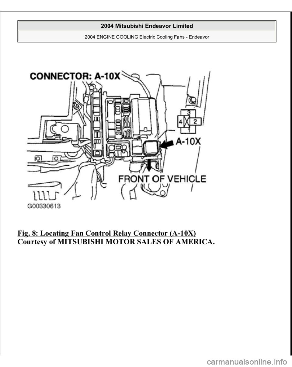
Fig. 8: Locating Fan Control Relay Connector (A
-10X)
Courtesy of MITSUBISHI MOTOR SALES OF AMERICA.
2004 Mitsubishi Endeavor Limited
2004 ENGINE COOLING Electric Cooling Fans - Endeavor