height adjustment MITSUBISHI GALANT 1989 Service User Guide
[x] Cancel search | Manufacturer: MITSUBISHI, Model Year: 1989, Model line: GALANT, Model: MITSUBISHI GALANT 1989Pages: 1273, PDF Size: 37.62 MB
Page 953 of 1273
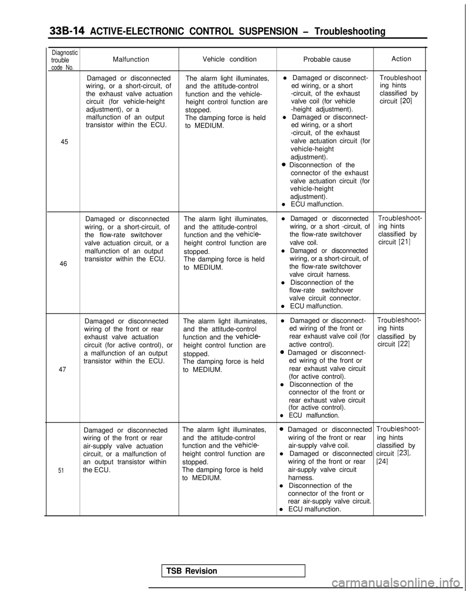
33B-14 ACTIVE-ELECTRONIC CONTROL SUSPENSION - Troubleshooting
DiagnostictroubleMalfunctionVehicle condition
Probable causeAction
code No.
Damaged or disconnected
The alarm light illuminates,l Damaged or disconnect-
Troubleshoot
wiring, or a short-circuit, of and the attitude-control ed wiring, or a shorting hints
the exhaust valve actuation function and the vehicle- -circuit, of the exhaust
classified by
circuit (for vehicle-height height control function are valve coil (for vehicle
circuit
[20]
adjustment), or a
stopped. -height adjustment).
malfunction of an output The damping force is heldl Damaged or disconnect-
transistor within the ECU. to MEDIUM. ed wiring, or a short
-circuit, of the exhaust
45valve actuation circuit (for
vehicle-height
adjustment).
0 Disconnection of the connector of the exhaust
valve actuation circuit (for
vehicle-height
adjustment).
l ECU malfunction.
46
Damaged or disconnected The alarm light illuminates,l Damaged or disconnected Troubleshoot-
wiring, or a short-circuit, of and the attitude-control
wiring, or a short -circuit, ofing hints
the flow-rate switchover function and the
vehicle-the flow-rate switchoverclassified by
valve actuation circuit, or a height control function are
valve coil.circuit [21]
malfunction of an output
stopped.l Damaged or disconnected
transistor within the ECU. The damping force is held wiring, or a short-circuit, of
to MEDIUM. the flow-rate switchover
valve circuit harness.
l Disconnection of the
flow-rate switchover
valve circuit connector.
l ECU malfunction.
47
Damaged or disconnected The alarm light illuminates,l Damaged or disconnect- Troubleshoot-
wiring of the front or rear and the attitude-control ed wiring of the front or
ing hints
exhaust valve actuation function and the
vehicle-rear exhaust valve coil (for
classified by
circuit (for active control), or height control function are active control).
circuit
[22]
a malfunction of an output
stopped.0 Damaged or disconnect-
transistor within the ECU. The damping force is held ed wiring of the front or
to MEDIUM. rear exhaust valve circuit
(for active control).
l Disconnection of the connector of the front or
rear exhaust valve circuit
(for active control).
l ECU malfunction.
51
Damaged or disconnected The alarm light illuminates,0 Damaged or disconnected Troubleshoot-
wiring of the front or rear and the attitude-control wiring of the front or rear
ing hints
air-supply valve actuation function and the
vehicle-air-supply valve
coil. classified by
circuit, or a malfunction of height control function arel Damaged or disconnected circuit
[23],
an output transistor within
stopped. wiring of the front or rear1241
the ECU.
The damping force is held air-supply valve circuit
to MEDIUM. harness.
l Disconnection of the connector of the front or
rear air-supply valve circuit.
l ECU malfunction.
TSB Revision
Page 954 of 1273
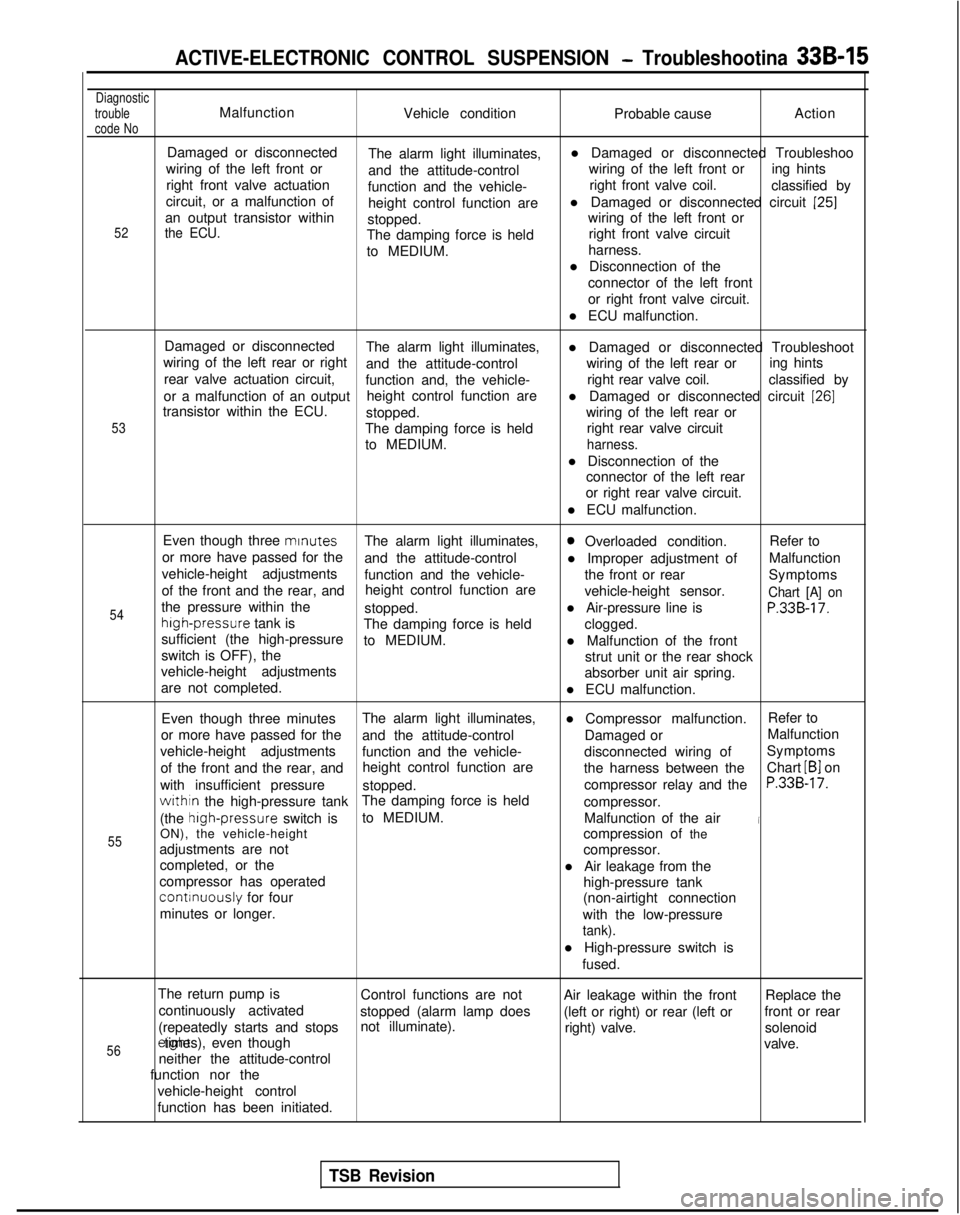
ACTIVE-ELECTRONIC CONTROL SUSPENSION - Troubleshootina 33B-15
Diagnostic
trouble
code NoMalfunction Vehicle condition Probable causeAction
52
Damaged or disconnected
The alarm light illuminates, l Damaged or disconnected Troubleshoo
wiring of the left front or and the attitude-control wiring of the left front or
ing hints
right front valve actuation function and the vehicle- right front valve coil.
classified by
circuit, or a malfunction of height control function arel Damaged or disconnected circuit
[25]an output transistor within
stopped. wiring of the left front orthe ECU.The damping force is held
right front valve circuit
to MEDIUM. harness.
l Disconnection of the connector of the left front
or right front valve circuit.
l ECU malfunction.
53
Damaged or disconnected The alarm light illuminates,
wiring of the left rear or right l Damaged or disconnected Troubleshoot
and the attitude-control wiring of the left rear or
rear valve actuation circuit, ing hints
function and, the vehicle- right rear valve coil.
classified by
or a malfunction of an output height control function are
transistor within the ECU. l Damaged or disconnected circuit
[26]
stopped.
wiring of the left rear or
The damping force is held right rear valve circuit
to MEDIUM.
harness.
l Disconnection of the connector of the left rear
or right rear valve circuit.
l ECU malfunction.
54
55
Even though three mrnutes
The alarm light illuminates,0 Overloaded condition. Refer to
or more have passed for the and the attitude-control l Improper adjustment ofMalfunction
vehicle-height adjustments function and the vehicle- the front or rear
of the front and the rear, and Symptoms
height control function are vehicle-height sensor.
Chart [A] onthe pressure within thestopped.l Air-pressure line isP.33B-17.high-pressure
tank is
The damping force is held
sufficient (the high-pressure clogged.
to MEDIUM. l Malfunction of the front
switch is OFF), the strut unit or the rear shock
vehicle-height adjustments absorber unit air spring.
are not completed. l ECU malfunction.
Even though three minutes The alarm light illuminates,
l Compressor malfunction.Refer to
or more have passed for the and the attitude-control Damaged orMalfunction
vehicle-height adjustments function and the vehicle- disconnected wiring ofSymptoms
of the front and the rear, and height control function are
the harness between theChart
LB1 on
with insufficient pressure stopped. compressor relay and the
P.33B-17.
withtn the high-pressure tankThe damping force is held
compressor.
(the high-pressure
switch isto MEDIUM.
Malfunction of the air
iON), the vehicle-height compression of the
adjustments are not compressor.
completed, or the l Air leakage from the
compressor has operated
continuously for four high-pressure tank
minutes or longer. (non-airtight connection
with the low-pressure
tank).
l High-pressure switch is fused.
The return pump is Control functions are not Air leakage within the frontReplace the
continuously activated stopped (alarm lamp does (left or right) or rear (left orfront or rear
(repeatedly starts and stops not illuminate).
right) valve.solenoid
56erght times), even though
valve.
neither the attitude-control
function nor the
vehicle-height control
function has been initiated.
TSB Revision
Page 956 of 1273
![MITSUBISHI GALANT 1989 Service User Guide ACTIVE-ELECTRONIC CONTROL SUSPENSION - Troubleshooting 33B-17
CHECKING ACCORDING TO CHARTS CLASSIFIED BY THE MALFUNCTION SYMPTOM
[A] DIAGNOSTIC TROUBLE CODE NO.54
No
Yes
b Excessive vehicle-height ad-](/img/19/57312/w960_57312-955.png "MITSUBISHI GALANT 1989 Service User Guide ACTIVE-ELECTRONIC CONTROL SUSPENSION - Troubleshooting 33B-17
CHECKING ACCORDING TO CHARTS CLASSIFIED BY THE MALFUNCTION SYMPTOM
[A] DIAGNOSTIC TROUBLE CODE NO.54
No
Yes
b Excessive vehicle-height ad-")
ACTIVE-ELECTRONIC CONTROL SUSPENSION - Troubleshooting 33B-17
CHECKING ACCORDING TO CHARTS CLASSIFIED BY THE MALFUNCTION SYMPTOM
[A] DIAGNOSTIC TROUBLE CODE NO.54
No
Yes
b Excessive vehicle-height ad-justment
(overload) overload). time (due to -Unload the vehicle and turn* the ignition key to OFF; then
restart the engine and check
whether or not the system
functions normally.
Is the installation position of Nothe height sensor correct?
Yes Improper setting of the heightc sensor, or malfunction of the
height sensor. l Correct the installationcposition of the height sen-
sor, or adjust the vehicle
-height sensor rod.
l Check the height sensor. Refer to troubleshooting
hints [IO] and
[ll]classified by circuit.
Are the front strut and rear
NoMalfunction of the rolling
shock absorber unit air spr-* diaphragm.
Repair the rolling diaphragm,
or replace the shock absorber
ings in normal condition?Lunit.
(become folded)
Yes
Is the sound of operation
NoThe solenoid valves remain
heard from each solenoid closed, or there is air leakage
valve necessary for th
e
’ due to a malfunction of the
vehicle-height adjustment? valve seat.
Yes
Is the air pressure in the
vehicle-height adjustment
Nopressure line 950 kPa (135
psi) or higher?
I
Yes Damaged or disconnected
wiring of the high-pressure
switch, or incorrect vehicle
-height adjustment pressureline.
l Check the high-pressure switch circuit.
* Refer to troubleshooting hint [5] classified by circuit.
l Correct the clogging pro-
blem, or replace the air
tube.
Control unit malfunction.
[B] DIAGNOSTIC TROUBLE CODE NO.55
- No
Does the compressor func-
tion normally?
Yes Replace the control unit.c l Power is not supplied to
the compressor.Refer to troubleshooting
hint
[18] classified by cir-
cuit.
0 Improper compressor com- pression.
Is the air pressure in the
Novehicle-height adjustment
pressure line 760 kPa (108psi) or lower? High-pressure
switch
isRefer to troubleshooting hint
shorted____* [5] classified by circuit.
Yes Air leakage.
TSB RevisionI
Page 960 of 1273
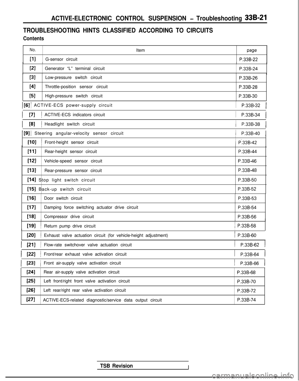
ACTIVE-ELECTRONIC CONTROL SUSPENSION - Troubleshooting 33B-21
TROUBLESHOOTING HINTS CLASSIFIED ACCORDING TO CIRCUITS
Contents
No.
PIG-sensor circuitItem
paw
P.33B-22/IPI
Generator “L” terminal circuit
P.33B-24
[31Low-pressure switch circuitP.33B-26
I41Throttle-position sensor circuitP.33B-28
[51High-pressure switch circuit P.338-30
) [6] / ACTIVE-ECS power-supply circuit
I PI IACTIVE-ECS indicators circuit
1 P.33B-32 1
1
P.33B-34 1
/ P.33B-38 1I L81 IHeadlight switch circuit
1 [9] / Steering angular-velocity sensor circuit/ P.33B-40 1
[lOI /
I
Front-height sensor circuit( P:33B-42I
PIIRear-height sensor circuit
[I21Vehicle-speed sensor circuit
[13]Rear-pressure sensor circuit
[I41 Stop light switch circuit
[I51 Back-up switch circuit
P.33B-44
P.33B46
P.33B-48 P.338-50
P.33B-52
TSB RevisionI
[If31Door switch circuitP.33B-53
[17]Damping force switching actuator drive circuit
P.338-54
1181Compressor drive circuitP.33B-561
WI
I
I
Return pump drive circuit/ P.33B-58
ml /
I
Exhaust valve actuation circuit (for vehicle-height adjustment)/ P.33B-60
I PII /Flow-rate switchover valve actuation circuit/ P.33B-62 1
I WI /Front/rear exhaust valve activation circuit1 P.33B-64 I
( 1231 1Front air-supply valve activation circuit1 P.33B-66 1
1241Rear air-supply valve activation circuitP.33B-68
[25]Left front/right front valve activation circuitP.33B-70
[=ILeft rear/right rear valve activation circuitP.33B-72
[271ACTIVE-ECS-related diagnostic/service data output circuitP.33B-74
Page 972 of 1273
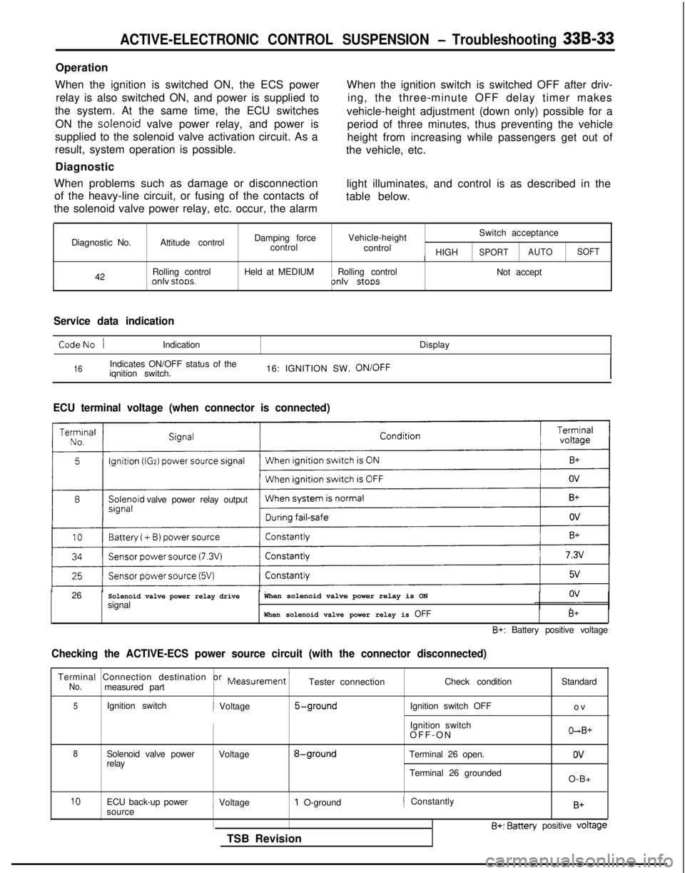
ACTIVE-ELECTRONIC CONTROL SUSPENSION - Troubleshooting 33B-33
Operation
When the ignition is switched ON, the ECS power relay is also switched ON, and power is supplied to
the system. At the same time, the ECU switches
ON the solenoid
valve power relay, and power is
supplied to the solenoid valve activation circuit. As a
result, system operation is possible.
Diagnostic
When problems such as damage or disconnection of the heavy-line circuit, or fusing of the contacts of
the solenoid valve power relay, etc. occur, the alarm When the ignition switch is switched OFF after driv-
ing, the three-minute OFF delay timer makes
vehicle-height adjustment (down only) possible for a period of three minutes, thus preventing the vehicle
height from increasing while passengers get out of
the vehicle, etc.
light illuminates, and control is as described in the
table below.
Diagnostic No. 42 Attitude control
Rolling control
onlv stoos.
Damping force
Vehicle-height Switch acceptance
control control
/ HIGHSPORTAUTOSOFT
Held at MEDIUM
Rolling control
Not acceptonlv stoos
Service data indication
CodeNo /Indication Display
16Indicates ON/OFF status of the
iqnition switch. 16: IGNITION SW. ON/OFF
ECU terminal voltage (when connector is connected)
valve power relay output
26
Solenoid valve power relay drivesignalWhen solenoid valve power relay is ON
When solenoid valve power relay is OFFB+
B+: Battery positive voltage
Checking the ACTIVE-ECS power source circuit (with the connector discon\
nected)
Terminal Connection destination or Measurement ’No.measured part Tester connection
Check condition
5Ignition switchi Voltage5-groundIgnition switch OFF
Ignition switch
OFF-O
N
8Solenoid valve power
Voltage8-groundTerminal 26 open.
relay
Terminal 26 groundedStandard
o
v
O+B+
ov
O-B+
10ECU back-up power
sourcei Voltage1 O-ground
TSB Revision/ ConstantlyB+
B+: Batten/ positive voltage
Page 982 of 1273
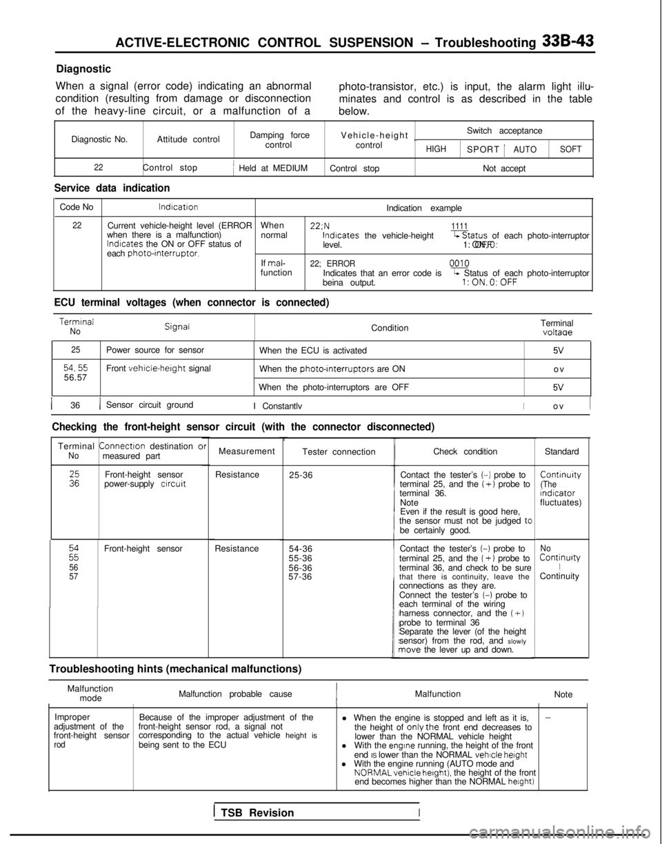
ACTIVE-ELECTRONIC CONTROL SUSPENSION - Troubleshooting 33B-43
Diagnostic
When a signal (error code) indicating an abnormal
condition (resulting from damage or disconnection
of the heavy-line circuit, or a malfunction of a photo-transistor, etc.) is input, the alarm light
illu-
minates and control is as described in the table
below.
Diagnostic No. Attitude control Damping force
Vehicle-height
~Switch acceptance
control control
HIGHSPORT 1AUTOSOFT
22
Control stopj Held at MEDIUM Control stop Not accept
Service data indication
Code No lndrcation
Indication example
22Current vehicle-height level (ERRORWhen 22:N1111when there is a malfunction)
normallndrcates
the ON or OFF status of lndtcates
the vehicle-height-Status of each photo-interruptor
level. 1: ON,O: OFF
each
photointerruptor.If mal-22; ERRORfunction
0010
Indicates that an error code isL Status of each photo-interruptor
beina output.l:ON.O:OFF
ECU terminal voltages (when connector is connected) Termrnal
NoCondition
Terminalvoltaae
25
54,5556.57Power source for sensor
Front vehicle-herght signal
When the ECU is activated
5V
When the photo-rnterruptors are ON
o
v
When the photo-interruptors are OFF
5V
1 36/ Sensor circuit ground I ConstantlvIo
v
I
Checking the front-height sensor circuit (with the connector disconnect\
ed)
Terminal
Connectron
destination cNomeasured part
:zFront-height sensor
power-supply crrcuit
22
56
57
Front-height sensor
Resistance
brMeasurement
Resistance 25-36Tester connection
54-36
55-36
56-36
57-36
t
Troubleshooting hints (mechanical malfunctions) Check condition
Standard
Contact the tester’s
(-1 probe to Contrnuity
terminal 25, and the ( + ) probe to(Theterminal 36.
rndrcator
Note fluctuates)
Even if the result is good here,
the sensor must not be judged
tcbe certainly good.
Contact the tester’s
(-1 probe to
terminal 25, and the (+ 1 probe to
terminal 36, and check to be sure
that there is continuity, leave the
connections as they are.
Connect the tester’s
(-1 probe to
each terminal of the wiring
harness connector, and the
(+ Jprobe to terminal 36
Separate the lever (of the height
sensor) from the rod, and slowly
nave the lever up and down.
No Continurty
IContinuity
Malfunction mode Malfunction probable cause
Malfunction
Note
Improper Because of the improper adjustment of the
-adjustment of the
front-height sensorfront-height sensor rod, a signal not
l When the engine is stopped and left as it is,
corresponding to the actual vehicle height is the height of onlythe front end decreases to
rodbeing sent to the ECU lower than the NORMAL vehicle height
l With the engrne running, the height of the front
end IS lower than the NORMAL vehicle
height
l With the engine running (AUTO mode and NORMALvehicle
hetght). the height of the front
end becomes higher than the NORMAL helght)
1 TSB RevisionI
Page 984 of 1273
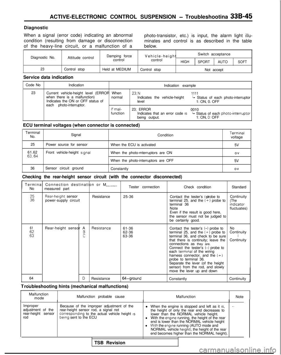
ACTIVE-ELECTRONIC CONTROL SUSPENSION - Troubleshootina 33B-45
Diagnostic
When a signal (error code) indicating an abnormal condition (resulting from damage or disconnection
of the heavy-line circuit, or a malfunction of a photo-transistor, etc.) is input, the alarm light
illu-
minates and control is as described in the table
below.
Diagnostic No. Attitude control
23Control stop
Service data indication Damping force
control
Held at MEDIUM Vehicle-heigh
t
Switch acceptance
control
HIGH SPORT AUTOSOFT
Control stop
Not accept
Code No Indication
Indication example
23 Current vehicle-height level (ERROR When 23;N
1111when there is a malfunction)
normal
Indicates the ON or OFF status of Indicates the vehicle-height
levelL Status of each photo-interruptor
each photo-interruptor. 1: ON, 0. OFF
If mal-23; ERROR0010
function Indicates that an error code IS
being output.L Status of each photointerruptor1: ON, 0. OFF
ECU terminal voltages (when connector is connected) Terminal
No.Signal Condition
25 Power source for sensor
When the ECU is activated
61.62
63,64Front vehicle-height sIgnalWhen the photo-mterruptors are ON
When the photo-interruptors are OFF
36 Sensor circuit ground
Constantly Terminal
voltage
5v
o
v
5V
o
v
Checking the rear-height sensor circuit (with the connector disconnecte\
d)
rTerminal Connection destination or
M
easurement
No measured part Tester connection
Check conditionStandardRear-herght
sensor
power-supply circuit Resistance
25-36 Contact the tester’s (-) probe to
Continuity
terminal 25. and the
(+) probe to(Theterminal 36 indrcator
Note fluctuates)
Even if the result is good here,
the sensor must not be judged to be certainly good.
61
Es
Rear-height sensor A Resrstance
61-36No
F
Contact the tester’s (-)
probe to
62-36 terminal 25, and the ( +) probe toContinuity
63-36 terminal 36, and check to be sureIthat there is continuity; leave the Continuity
connections as they are.
Connect the tester’s
(-1 probe to
each termrnal
of the wiring
harness connector, and the
( +)probe to terminal 36. Separate the lever (of the height
sensor) from the rod, and slowly
move the lever up and down
64
- _. .
DResistance64-groundConstantly Continuity
1 roubleshooting hints (mechanical malfunctions)
Malfunctionmode Malfunction probable cause
MalfunctionNote
Improper Because of the improper adjustment of the l When the engine is stopped and left as it IS,
-adjustment of the
rear-height sensorrear-height sensor rod, a signal not
the height of only the rear end decreases to
rod correspondrng
to the actual vehicle height IS berng
sent to the ECU lower than the NORMAL vehicle height.lWith the engrne running, the height of the rear
end is lower than the NORMAL vehicle height
lWith the engine
running (AUTO mode and
NORMAL vehicle herght). the height of the rear
end becomes higher than the NORMAL height).
TSB Revision
Page 998 of 1273
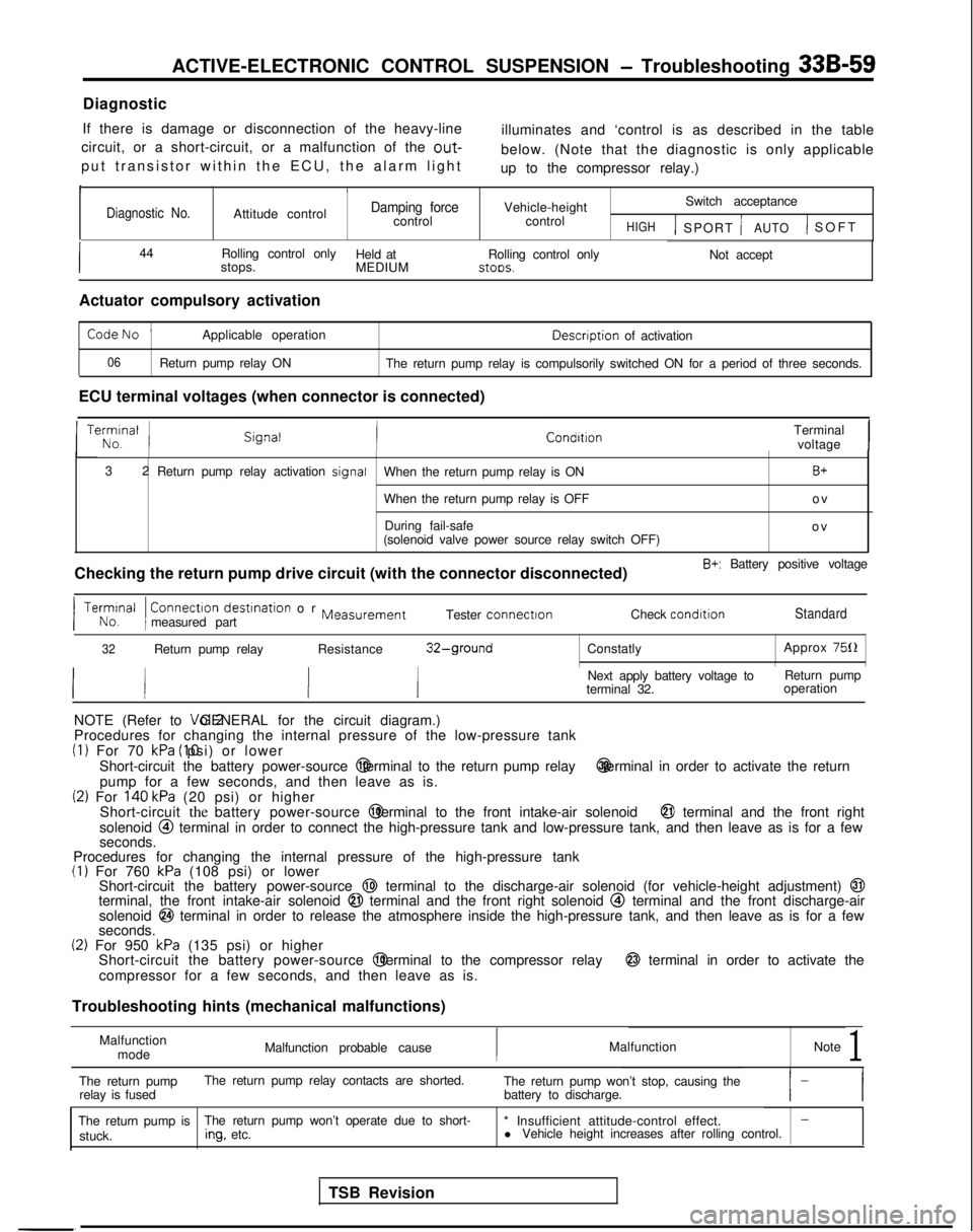
ACTIVE-ELECTRONIC CONTROL SUSPENSION - Troubleshooting 33B-59
Diagnostic
If there is damage or disconnection of the heavy-line illuminates and ‘control is as described in the table
circuit, or a short-circuit, or a malfunction of the
out-
put transistor within the ECU, the alarm ligh
t
below. (Note that the diagnostic is only applicable
up to the compressor relay.)
II/6
Diagnostic No.Attitude controlDamping forcecontrol Vehicle-height
control Switch acceptanceHIGH1 SPORT jAUTO) SOF
T
I44
Rolling control only
Held at
stops. MEDIUMRolling control only stoos.
Not accept
Actuator compulsory activation
CodeNo ’Applicable operation Descnption
of activation
06Return pump relay ON
The return pump relay is compulsorily switched ON for a period of three \
seconds.
ECU terminal voltages (when connector is connected) Terminalvoltage
I
3
2
Return pump relay activation signal
When the return pump relay is ON
B+
When the return pump relay is OFF o
v
During fail-safe ov
(solenoid valve power source relay switch OFF)
Checking the return pump drive circuit (with the connector disconnected\
)
B+: Battery positive voltage Connectron
destrnation or Measurementmeasured part Tester connectron
Check condrtronStandard
32Return pump relay
Resistance32-groundConstatly Approx 750INext apply battery voltage to
terminal 32. Return pump
operation
NOTE (Refer to Vol.2 GENERAL for the circuit diagram.)
Procedures for changing the internal pressure of the low-pressure tank
(1) For 70 kPa (IO psi) or lower
Short-circuit the battery power-source @ terminal to the return pump relay @ terminal in order to activate the return
pump for a few seconds, and then leave as is.
(2) For 140 kPa (20 psi) or higher
Short-circuit the battery power-source @ terminal to the front intake-air solenoid @I terminal and the front right
solenoid @I terminal in order to connect the high-pressure tank and low-pressure ta\
nk, and then leave as is for a few
seconds.
Procedures for changing the internal pressure of the high-pressure tank
(I) For 760 kPa (108 psi) or lower
Short-circuit the battery power-source @I terminal to the discharge-air solenoid (for vehicle-height adjustment)\
@Iterminal, the front intake-air solenoid @I terminal and the front right solenoid @ terminal and the front discharge-air
solenoid @I terminal in order to release the atmosphere inside the high-pressure ta\
nk, and then leave as is for a few
seconds.
(2) For 950 kPa (135 psi) or higher
Short-circuit the battery power-source @ terminal to the compressor relay @ terminal in order to activate the
compressor for a few seconds, and then leave as is.
Troubleshooting hints (mechanical malfunctions)
Malfunctionmode Malfunction probable cause
Malfunction
Note
1
The return pumpThe return pump relay contacts are shorted.
relay is fused The return pump won’t stop, causing the
battery to discharge.
The return pump is The return pump won’t operate due to short-
* Insufficient attitude-control effect.
-
stuck.ing.
etc. l
Vehicle height increases after rolling control.
TSB Revision
Page 999 of 1273
![MITSUBISHI GALANT 1989 Service User Guide 33B-60 ACTIVE-ELECTRONIC CONTROL SUSPENSION - Troubleshooting
[20] EXHAUST VALVE ACTIVATION CIRCUIT (FOR VEHICLE-HEIGHT ADJUSTMENT)Exhaust valve
[for vehicle-height
adjustment)
Usually OFF; ON
vehicle](/img/19/57312/w960_57312-998.png "MITSUBISHI GALANT 1989 Service User Guide 33B-60 ACTIVE-ELECTRONIC CONTROL SUSPENSION - Troubleshooting
[20] EXHAUST VALVE ACTIVATION CIRCUIT (FOR VEHICLE-HEIGHT ADJUSTMENT)Exhaust valve
[for vehicle-height
adjustment)
Usually OFF; ON
vehicle")
33B-60 ACTIVE-ELECTRONIC CONTROL SUSPENSION - Troubleshooting
[20] EXHAUST VALVE ACTIVATION CIRCUIT (FOR VEHICLE-HEIGHT ADJUSTMENT)Exhaust valve
[for vehicle-height
adjustment)
Usually OFF; ON
vehicle-height
downward Air cleaner
0lOOA Main fusible
4-J link
R&Vbox
F-17
l!!!b
Malfunctm*e*ectwn
ctrcwt
A-l 1
2
8 (
1;
*-1mm =
Exhaust valve
for
vehicle-heightadjustment >
12A0251
*: 1991 models1312AO498
TSB Revision
Page 1000 of 1273
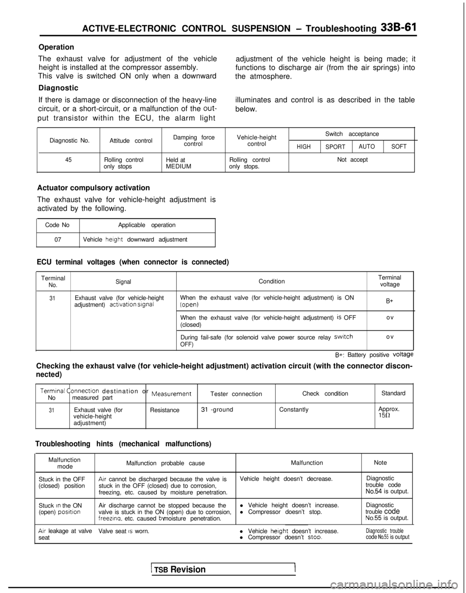
ACTIVE-ELECTRONIC CONTROL SUSPENSION - Troubleshooting 33B-61
Operation
The exhaust valve for adjustment of the vehicle height is installed at the compressor assembly.
This valve is switched ON only when a downward
Diagnostic
If there is damage or disconnection of the heavy-line
circuit, or a short-circuit, or a malfunction of the out-
put transistor within the ECU, the alarm light adjustment of the vehicle height is being made; it
functions to discharge air (from the air springs) into
the atmosphere.
illuminates and control is as described in the table
below.
Diagnostic No.
45
Attitude control
Rolling control
only stops Damping force
control
Held at
MEDIUM Vehicle-height
control
Rolling control
only stops. Switch acceptanceHIGHSPORT
AUTO
SOFT
Not accept
Actuator compulsory activation
The exhaust valve for vehicle-height adjustment is activated by the following.
Code No Applicable operation
07 Vehicle height
downward adjustment
ECU terminal voltages (when connector is connected)
TerminalNo. SignalCondition Terminal
voltage
31Exhaust valve (for vehicle-height
adjustment) activation srgnalWhen the exhaust valve (for vehicle-height adjustment) is ON (open)
When the exhaust valve (for vehicle-height adjustment)
is OFF
(closed)
B+
o
v
During fail-safe (for solenoid valve power source relay
swatcho
v
OFF)
B+: Battery positive voltage
Checking the exhaust valve (for vehicle-height adjustment) activation \
circuit (with the connector discon-
nected)
Termtnal
Connectlon destination or MeasurementCheck condition Standard
No measured part Tester connection
31Exhaust valve (for
Resistance31 -groundConstantly Approx.
vehicle-height1511adjustment)
Troubleshooting hints (mechanical malfunctions)
Malfunction mode Malfunction probable cause
Malfunction
Note
Stuck in the OFF
Arr cannot be discharged because the valve is Vehicle height doesn’t decrease.Diagnostic
(closed) position stuck in the OFF (closed) due to corrosion, trouble code
freezing, etc. caused by moisture penetration.
No.54 is output.
Stuck
rn the ON
(open) positlonAir discharge cannot be stopped because the l Vehicle height doesn’t increase.Diagnostic
valve is stuck in the ON (open) due to corrosion, l Compressor doesn’t stop.trouble codefreezlna.
etc. caused bv moisture penetration.No.55 is output.
Arr leakage at valve
Valve seat IS worn.
seat l Vehicle herght
doesn’t increase.
l Compressor doesn’t stoo.Diagnostic troublecode No.55 is output
1 TSB Revision