height adjustment MITSUBISHI GALANT 1989 Service Owner's Guide
[x] Cancel search | Manufacturer: MITSUBISHI, Model Year: 1989, Model line: GALANT, Model: MITSUBISHI GALANT 1989Pages: 1273, PDF Size: 37.62 MB
Page 1035 of 1273
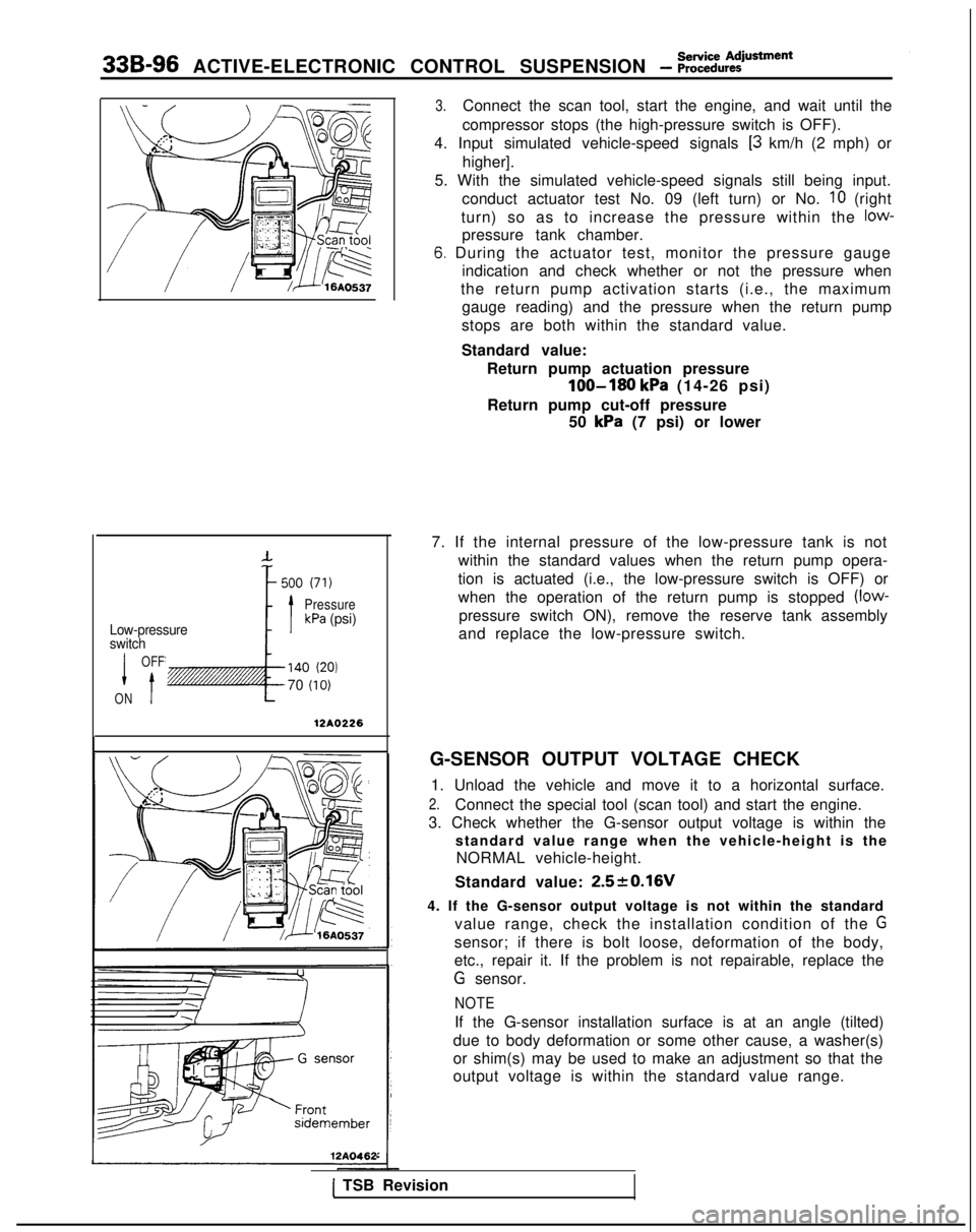
338-96
ACTIVE-ELECTRONIC CONTROL SUSPENSION - ;;~:;u~:iusment
Low-pressure
switch
PressurekPa (psi)
I
OFF
t
140 (20)
70 (10)
ON
12AO226
12A04P
3.Connect the scan tool, start the engine, and wait until the
compressor stops (the high-pressure switch is OFF).
4. Input simulated vehicle-speed signals
[3 km/h (2 mph) or
higher].
5. With the simulated vehicle-speed signals still being input. conduct actuator test No. 09 (left turn) or No.
IO (right
turn) so as to increase the pressure within the
low-
pressure tank chamber.
6. During the actuator test, monitor the pressure gauge indication and check whether or not the pressure when
the return pump activation starts (i.e., the maximum gauge reading) and the pressure when the return pump
stops are both within the standard value.
Standard value: Return pump actuation pressure
loo-180 kPa (14-26 psi)
Return pump cut-off pressure 50
kPa (7 psi) or lower
7. If the internal pressure of the low-pressure tank is not within the standard values when the return pump opera-
tion is actuated (i.e., the low-pressure switch is OFF) or
when the operation of the return pump is stopped
(low-
pressure switch ON), remove the reserve tank assembly
and replace the low-pressure switch.
G-SENSOR OUTPUT VOLTAGE CHECK 1. Unload the vehicle and move it to a horizontal surface.
2.Connect the special tool (scan tool) and start the engine.
3. Check whether the G-sensor output voltage is within the standard value range when the vehicle-height is theNORMAL vehicle-height.
Standard value:
2.520.16V
4. If the G-sensor output voltage is not within the standard value range, check the installation condition of the
G
sensor; if there is bolt loose, deformation of the body,
etc., repair it. If the problem is not repairable, replace the
G sensor.
NOTE
If the G-sensor installation surface is at an angle (tilted)
due to body deformation or some other cause, a washer(s)
or shim(s) may be used to make an adjustment so that the
output voltage is within the standard value range.
1 TSB Revision
Page 1050 of 1273
Shock AbsorberACTIVE-ELECTRONIC CONTROL SUSPENSION - Assembly339-111
(2) Remove the shock absorber upper mounting nuts andthe lower mounting bolts, and then remove the shock
absorber assembly.
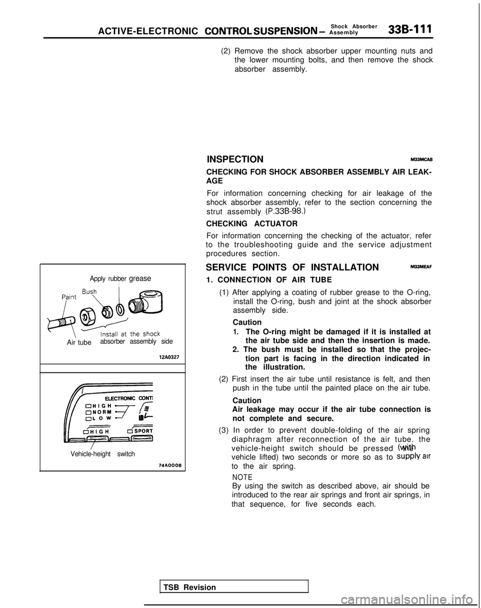
Apply rubber greaseI
Air tubeabsorber assembly side 12A0327
Vehicle-height switch
741IOO08INSPECTION
M33McA8
CHECKING FOR SHOCK ABSORBER ASSEMBLY AIR LEAK-
AGE
For information concerning checking for air leakage of the
shock absorber assembly, refer to the section concerning the
strut assembly
(P.33B-98.)
CHECKING ACTUATOR
For information concerning the checking of the actuator, refer
to the troubleshooting guide and the service adjustment procedures section.
SERVICE POINTS OF INSTALLATION
M33MEAF
1. CONNECTION OF AIR TUBE (1) After applying a coating of rubber grease to the O-ring, install the O-ring, bush and joint at the shock absorber
assembly side.
Caution
1.The O-ring might be damaged if it is installed at
the air tube side and then the insertion is made.
2. The bush must be installed so that the projec-
tion part is facing in the direction indicated in
the illustration.
(2) First insert the air tube until resistance is felt, and then push in the tube until the painted place on the air tube.
Caution
Air leakage may occur if the air tube connection is
not complete and secure.
(3) In order to prevent double-folding of the air spring diaphragm after reconnection of the air tube. the
vehicle-height switch should be pressed (wrth the
vehicle lifted) two seconds or more so as to
Supply air
to the air spring.
NOTE
By using the switch as described above, air should be
introduced to the rear air springs and front air springs, in
that sequence, for five seconds each.
TSB Revision
Page 1057 of 1273
33B-118
ACTIVE-ELECTRONIC CONTROL SUSPENSION - Lateral Rod
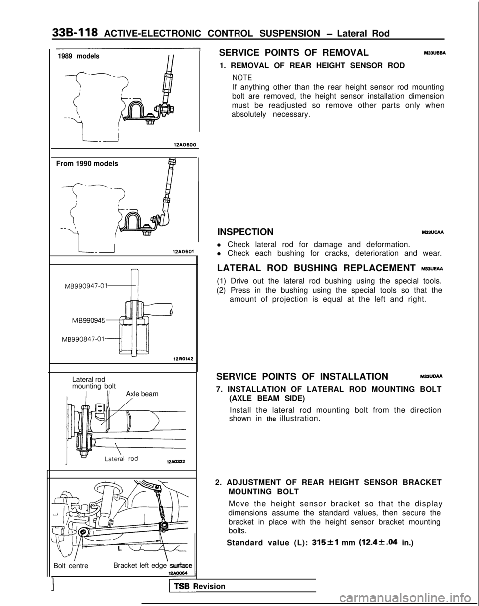
1989 modelsSERVICE POINTS OF REMOVAL M22UB6A
1. REMOVAL OF REAR HEIGHT SENSOR ROD
NOTE
If anything other than the rear height sensor rod mounting
bolt are removed, the height sensor installation dimension
must be readjusted so remove other parts only when
absolutely necessary.
\
12A0600
From 1990 models
-f
--_
(-_ \
41
L-r12A0601
MB990947-01-4 12R0142
Lateral rod
mounting bolt
IIIAxle beam
12Ao322
Move the height sensor bracket so that the displa
y
dimensions assume the standard values, then secure the bracket in place with the height sensor bracket mounting
bolts.
Standard value (L):
315&l mm (12.4k.04 in.)
Bolt centre
;’Bracket left edge surface,
TSB Revision INSPECTION M22UCAA
l Check lateral rod for damage and deformation.
l Check each bushing for cracks, deterioration and wear.
LATERAL ROD BUSHING REPLACEMENT
WUEAA
(1) Drive out the lateral rod bushing using the special tools.
(2) Press in the bushing using the special tools so that the amount of projection is equal at the left and right.
SERVICE POINTS OF INSTALLATION M22UDAA
7. INSTALLATION OF LATERAL ROD MOUNTING BOLT (AXLE BEAM SIDE)
Install the lateral rod mounting bolt from the direction
shown in the illustration.
2. ADJUSTMENT OF REAR HEIGHT SENSOR BRACKET MOUNTING BOLT
Page 1074 of 1273
ACTIVE-ELECTRONIC CONTROL SUSPENSION - Heiaht Sensor 33B-135
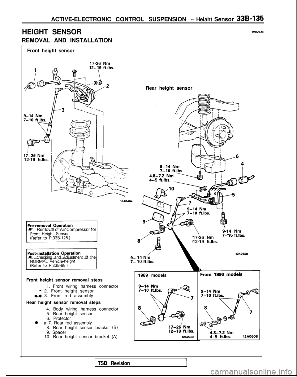
HEIGHT SENSOR
REMOVAL AND INSTALLATION
Front height sensor
17-26 Nm
li-26 Nm
12-19 ft.lbs.
l Removal of Air Compressor for
17-26 Nm
I- I” n.,os.
12-19 ft.lbs.
l checking and Adjustment of the14 Nm
10 ftlbs.
1989 models
Front height sensor removal steps
1. Front wiring harness connector* 2. Front height sensore+ 3. Front rod assembly
Rear height sensor removal steps 4. Body wiring harness connector5. Rear height sensor
6. Protector
l a 7. Rear rod assembly
8. Rear height sensor bracket
(B)9. Spacer
10. Rear height sensor bracket (A)l2A0358 12AO464
M332TAE
Rear height sensor
9-14 Nm
- .a #.&IL- 12AO358
‘19901
i.8-7.2 Nm
4-5 ft.lbs.12A0608
TSB Revision
Page 1075 of 1273
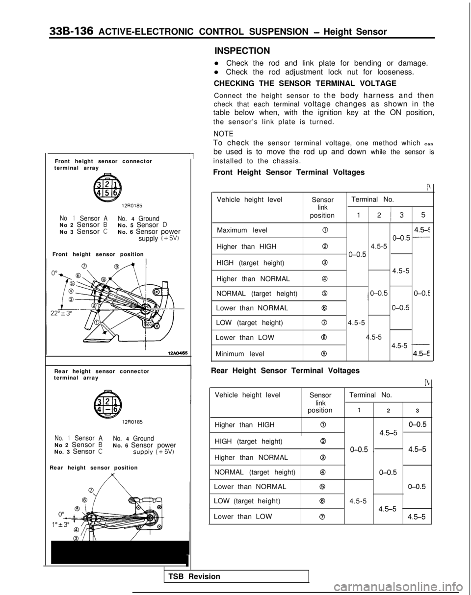
33B-136 ACTIVE-ELECTRONIC CONTROL SUSPENSION - Height Sensor
Front height sensor connector
terminal array
1
1270185
No1SensorA No.4GroundNo 2 Sensor BNo. 5 Sensor DNo 3 Sensor CNo. 6 Sensor power
supply i + 5W
Front height sensor position
Rear height sensor connector
terminal array
12R0185
No.1Sensor ANo.4GroundNo 2 Sensor BNo. 6 Sensor power
No. 3 Sensor CSUPPlY (+ 5w
Rear height sensor position
1
TSB Revision INSPECTION
l Check the rod and link plate for bending or damage.
l Check the rod adjustment lock nut for looseness.
CHECKING THE SENSOR TERMINAL VOLTAGE
Connect the height sensor to the body harness and then
check that each terminal voltage changes as shown in the
table below when, with the ignition key at the ON position,
the sensor’s link plate is turned.
NOTE
To check the sensor terminal voltage, one method which can
be used is to move the rod up and down while the sensor is
installed to the chassis.
Front Height Sensor Terminal Voltages
P
Vehicle height level SensorTerminal No.
link
position
1 2I3 5
Maximum level04.5-E
o-o.5 -
Higher than HIGH04.5-5
o-o.5
HIGH (target height)0
4.5-5
Higher than NORMAL
@
NORMAL (target height)0/ o-o.5O-O.!
Lower than NORMAL63o-o.5
LOW (target height)04.5-5
Lower than LOW Q 4.5-5
4.5-5
-
Minimum level84.5-E
Rear Height Sensor Terminal Voltages
b
Vehicle height level SensorTerminal No.
link
position
12 3
Higher than HIGH
0o-o.5
4.5-5
HIGH (target height)0
o-o.5 .4.5-5
Higher than NORMAL0
NORMAL (target height)63o-o.5
Lower than NORMAL0o-o.5
LOW (target height)84.5-5
4.5-5Lower than LOW04.5-5
Page 1174 of 1273

SERVICE BRAKES - Service Adjustment Procedures35-53
switch
switch
c/ 14F516
Pedal
Idown /
\ \
F14517
TSB Revision
F14518
SERVICE ADJUSTMENT PROCEDURES
BRAKE PEDAL INSPECTION AND ADJUSTMAN-
1.Measure the brake pedal height as illustrated. If the brake
pedal height is not within the standard value, adjust as
follows.
Standard value (A): 176-181 mm (6.9-7.1 in.)
(1) Disconnect the stop light switch connector, loosen the
lock nut, and move the stop light switch to a position
where it does not contact the brake pedal arm.
(2) Adjust the brake pedal height by turning the operating
rod with pliers (with the operating rod lock nut
loosened), until the correct brake pedal height is
obtained.
(3) After screwing in the stop light switch until it contactsthe brake pedal stopper (just before the brake pedal is
caused to move), return the stop light switch l/2
to 1
turn and secure by tightening the lock nut.
2.
(4) Connect the connector of the stop light switch.
(5) Check to be sure that the stop light is not illuminated
with the brake pedal unpressed.
Reference value
(B): 0.5-1.0 mm (.02-.04 in.)
With the engine stopped, depress the brake pedal two or
three times. After eliminating the vacuum in the power
brake booster, press the pedal down by hand, and confirm
that the amount of movement before resistance is met
(the free play) is within the standard value range.
Standard value
(C): 3-8 mm (.l-.3 in.)
If the free play is less than the standard value, confirm that
the clearance between the stop light switch and brake pedal is within the standard value.
If the free play exceeds the standard value, it is probably
due to excessive play between the clevis pin and brake
pedal arm. Check for excessive clearance and replace
faulty parts as required.
Page 1175 of 1273
35-54SERVICE BRAKES - Service Adjustment Procedures
F14519
14UOO61
When engine isstopped
No good
0
w
\/‘14UOO62z;redengine
is
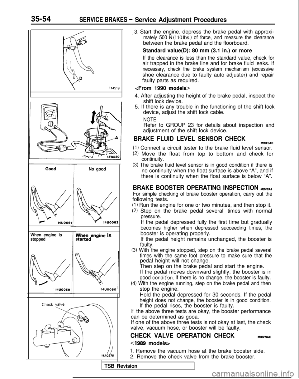
14UOO60 ,3.
Start the engine, depress the brake pedal with approxi-
mately 500 N (110 Ibs.) of force, and measure the clearance
between the brake pedal and the floorboard.
Standard value(D): 80 mm (3.1 in.) or more
If the clearance is less than the standard value, check for
air trapped in the brake line and for brake fluid leaks. If
necessary, check the brake system mechanism (excessive
shoe clearance due to faulty auto adjuster) and repair
faulty parts as required.
4. After adjusting the height of the brake pedal, inspect the shift lock device.
5. If there is any trouble in the functioning of the shift lock device, adjust the shift lock cable.
NOTE
Refer to GROUP 23 for details about inspection and
adjustment of the shift lock device.
BRAKE FLUID LEVEL SENSOR CHECKM35F6A6
(1) Connect a circuit tester to the brake fluid level sensor.
(2) Move the float from top to bottom and check for
continuity.
(3) The brake fluid level sensor is in good condition if there is
no continuity when the float surface is above “A”, and if
there is continuity when the float surface is below “A”.
BRAKE BOOSTER OPERATING INSPECTION MlKcAJ
For simple checking of brake booster operation, carry out the
following tests.
(1) Run the engine for one or two minutes, and then stop it.
(2) Step on the brake pedal several’ times with normal
pressure.
If the pedal depressed fully the first time but gradually
becomes higher when depressed succeeding times, the
booster is operating properly.
If the pedal height remains unchanged, the booster is
faulty.
(3) With the engine stopped, step on the brake pedal several
(4
If
times with the same foot pressure to make sure that the
pedal height will not change.
Then step on the brake pedal and start the engine.
If the pedal moves downward slightly, the booster is in
good condit’on. If there is no change, the booster is faulty.
.) With the engine running, step on the brake pedal and then
stop the engine.
Hold the pedal depressed for 30 seconds. If the pedal
height does not change, the booster is in good condition.
If the pedal rises, the booster is faulty.
the above three tests are okay, the booster performance
can be determined as gooa.
If one of the above three tests is not okay at last, the check
valve, vacuum hose, or booster will be faulty.
CHECK VALVE OPERATION CHECKM3!3FNAK
cl989 models>
1. Remove the vacuum hose at the brake booster side.
2. Remove the check valve from the brake booster.
TSB Revision
Page 1265 of 1273
4ALPHABETICAL INDEX
DOHC-Turbo.................................
. 15-31-f
SOHC-8VALVE..................................
.
15-27-t
SOHC-1 GVALVE............................
.
15-28-l
EXHAUST PIPEDOH
C
......................... 15-33-I
SOHC.....................................
.
15-32-l
EXHAUST SYSTEM, Maintenance ..................... 00-45-I
F
FAN MOTOR
Condenser
.............................
.
55-48-l
Radiator...................
.
......... 14-12-I
FEEDER CABLE ..........................
54-l 55-11FENDER................................
.
42-61-t
FILLER DOOR, Fuel Tank.........................
.
42-60-I
FILLER TUBE CAP, Fuel Tank, Inspection...............
.
17-21 -I
FILTER
Engine 011. Maintenance ....................
. 00-41-I
Fuel
Fuel
.
...................
13-I 15-lFuel
.
13-195
FITTINGS, Handling................................
. 55-22-l
FIXED SAS
Adjustment
........................
.
13-250-I
Adjustment
.
13-138-I
FLAT BATTERY, Remedy............................
.
35-75-l
FLOOR CONSOLE................................
.
52-29-l
FLUID
Power Steering, Level Check
...................
. 37A-21-l
Power Steering, Replacement ................. 37A-21-l
Transaxle, Replacement ..................... 23-82-l
FLUID LEVEL, Transaxle, Inspection .................. 23-82-l
FOG LIGHT................
.
......................
54-94-11FOG LIGHT SWITCH................................
.
54-99-114WS, Function Check
..........................
. 37B-6-l
FRONT BRAKE DISC
Run-out Check
...................................
. 35-63-I
Run-out Correction ........................... 35-64-l
Thickness Check .............................. 35-65-l
FRONT DISC BRAKE.................................
. 35-94-l
FRONT DISC BRAKE PAD, Check and Replacement ......... 35-59-l
FRONT DOOR DRIP LINE WEATHERSTRIP 42-112-I
FRONT DOOR GLASS...............................
. 42-80-l
FRONT DOOR HANDLE.........................
. 42-96-l
FRONT DOOR LATCH...
.
......... .......... 42-96-l
FRONT DOOR
MOULDING
........................... 42-112-I
FRONT DOOR REGULATOR........................
. 42-80-I
FRONT DOOR TRIM.................................
. 42-76-l
FRONT DOOR WATERPROOF FILM....................
. 42-76-l
FRONT GRILLE..................................
. 51-12-l
FRONT SEAT,...................................
. 52-35-l
FRONT WHEEL ALIGNMENT Adjustment
. 338-86-I
Adjustment
FUEL FILTER
DOHC
.......................................
. 13-327-I
SOHC-8VALVE
.................................
13-l 15-l SOHC-IGVALVE
................................ 13-195-I
FUEL HOSES, Maintenance ............................
00-39-1
FUEL LINE
DOHC-AWD ..................................
.
13-326-l
DOHC-FWD....................................
.
13-324-l
SOHC-8VALVE
................................. 13-113-l
SOHC-1 ~VALVE............................
.
13-l 95-IFUEL PRESSURE
On-vehicle Inspection
On-vehicle Inspection
On-vehicle Inspection
FUEL PRESSURE SOLENOID
On-vehicle Inspection
FUEL PUMP
On-vehicle Inspection
On-vehicle Inspection
On-vehicle Inspection
FUEL SYSTEM, Maintenanc
e
FUEL TANK
DOHC-AWD .,.......
DOHC-FW
D
SOHC-8VALVE
SOHC-16VALVE
FUEL TANK FILLER DOO
R
FUEL TANK FILLER TUBE CAP, Inspection
FUEL TANK PRESSURE CONTROL VALVE. 13-312-l
13-102-I
,.....13-I
92-l
13-307-I
......
13-258-l
....... 13-46-l
...... 13-147-l
....... 00-39-l
......
13-322-l
...... 13-318-l
..... 13-109-I
...... 13-195-I
....... 42-60-I
....... 17-21-I
....... 17-21-l
G
GARNISHES
51-13-l
GASKET
Cylinder Head
Cylinder Head
GAUGE UNIT, Engine Coolant Temperature
14-31-l
GEAR BOX, Power Steering 37A-32-l
GEAR OIL, Level Check
GENERATOR
16-g-11
GLASS
Door, Adjustmen
t
42-52-l
Door, Front 42-80-I
Door, Rear 42-83-l
Quarter Window 42-70-I
Window.............
.._......_...... 42-63-i
Window,Rear
42-72-i
GRILLE,Front
_. _. _.
51-12-l
G-SENSOR
Service Brakes
35-132-l
Output Voltage, Check 336-96-l
H
HANDLE
Door, Front
..........................
.
Door,Rear
...........................
Door Inside, Play Check. ..................
HAZARD SWITCH.........................
.
HEADLIGHTS............................
.
HEADLINING.............................
.
HEATED OXYGEN SENSOR, On-vehicle Inspection
>
...............................
HEATER CONTROL.......................
.
HEATER UNIT............................
.
HEIGHT SENSOR.........................
.
HIGH MOUNTED STOP LIGHT...............
.
42-96-1 42-99-l
42-52-l
54-98-11
54-92-11
52-31-l
13-290-I
55-25-l
55-30-I
338-l
35-l
54-96-11HIGH PRESSURE SWITCH (HIGH-PRESSURE TANK SIDE),Actuation Pressure Check. 338-94-I
16-42-11
42-55-l
42-50-I
54-l 03-11
54-105-11
HIGH TENSION CABLE, Spark Test
HOOD .__...._..._......__._...................
HOOD, Alignment Adjustment .
HOR
N
. . . . . . . . . . . . . . . . . . . . . . . . . . . . . . . . . . . . \
. . . HORNRELAY
._.._._....___.........__.._._..___
HOSE
Brake, Maintenance
.
00-45-I
Page 1267 of 1273
6ALPHABETICAL INDEX
LOW PRESSURE SWITCH (LOW-PRESSURE TANK SIDE)
Actuation Pressure Check
.
M
MAIN MUFFLER
DOH
C
SOHC
MANIFOLD
Exhaust
Exhaust
Exhaust
Exhaust
Intake
Intake
Intake
Vacuum Inspection
Vacuum Inspection
MANUAL TRANSAXLE
AWD
FW
D
Maintenance
MASTER CYLINDER
Clutch
Service Brakes.
METER, Boost, On-vehrcle
Inspectron
METERS AND GAUGES
MIRROR, Door
MIRROR SWITCH. Remote Controlled
MIXTURE CONTROL [MFI) SYSTEM : : : : : :
MODE SELECTOR SWITCH EPS
MOTOR 15-30-I
15-31 -I
15-27-l
15-28-l
15-21-l
15-14-l
15-18-l
11-60-I
11-9-l
22-l 5-l
22-2-i
00-42-l
21-12-l
35-81 -I
13-311-I
54-8-11
51-33-l
51-34-l
17-29-l
37A-59-l
Idle Arr Control (DC Motor), On-vehicle Inspection
Idle Air Control (Stepper Motor), On-vehicle Inspection
Idle Speed Control (DC Motor),
6n-vehicle
Inspection
Starte
r
MOULDING
Door. Front
Door. Rear
Exterio
r
MOUNTING 42-112-l
42-1 14-l
51-15-l
Engine.
,,,.....
Transaxl
e
MUFFLER
Main
Main
> 32-4-l
32-5-l
15-33-l
15-32-I
N
NOISE. Compressor, Adjustmen
t
NORMAL VEHICLE HEIGHT, Check and Adjustment
OIL 55-23-l
338-88-I
0
Engine. Check
Engine. Check
1 : : 1 : 1
Engine, Maintenance.
.
Transaxle. Replacement
Transaxle. Replacement
Transfer. Replacemen
t
OIL COOLER HOSES, Transaxle
OIL FILTER, Engine, Maintenance. 11-57-l
11-7-l
00-41-I
22-18-l
22-4-l
23-82-l
23-l
00-l
00-41 -I338-95-I
15-33-l
15-32-l
13-l
84-l
13-298-l
13-93-l
16-19-f
OIL LEVEL
Gear, Check
.
27-l 5-f
Transaxle, Inspection
. 22-17-l
Transaxle, Inspection
. 22-4-l
Transfer, Inspection ............................... 23-82-l
OIL LINE, Rear. .............. ..................... 378-13-I
OIL PAN
DOHC.....................................
. 11-71-l
SOHC......
.
.................................. 11-23-l
OIL PRESSURE SWITCH, Power Steering. Check ........... 37A-24-l
OIL PUMP Power Steering ................................. 37A-48-l
Power Steering, Pressure Test ...................... 37A-23-l
Rear..........
.
...
......................... 378-15-I
...
Rear, Discharge Flow Volume Check .................. 378-6-I “s
OIL SCREEN.
DOHC.....................................
.
11-71-l
SOHC.
......................................
.
1 l-23-l
OIL SEALS Camshaft
Camshaft
........................... 11-19-l
Drive Shaft. Replacement .................... 23-92-l
Drive Shaft, Replacement
. 22-18-l
Drive Shaft, Replacement
. 22-4-l
Transfer, Replacement
. 22-19-l
OUTPUT VOLTAGE,
G sensor, Check ..................
. 33B-96-l
OXYGEN SENSOR
On-vehicle
inspectron
.
13-87-l
On-vehicle Inspection
. 13-179-l
P
PAD
Disc Brake. Front, Check and Replacement ............
. 35-59-l
Disc Brake. Maintenance. ........................... 00-44-i
Disc Brake. Rear, Check and Replacement
’.............
. 35-65-l
PANEL. Loose ....................................... 42-62-l
PARKING BRAKE CABLE..............................
. 36-5-l
PARKING BRAKE LEVER...............................
. 36-4-l
PARKING BRAKE LEVER, Stroke Check...................
. 36-2-l
PARKING BRAKE SWITCH, Check.......................
. 36-3-l
PARK/NEUTRAL POSITION SWITCH
Adjustment ..................................... 23-84-l
On-vehrcle
Inspection
On-vehicle Inspection
On-vehicle Inspection
PCV VALVE, Inspection
................................ 17-14-l
PEDAL
Brake
..........................................
. 35-76-l
Brake, Inspection
and Adjustment
.................... 35-53-l
Clutch.........................................
. 21-7-l
Clutch. Inspection
and Adjustment
..................... 21-5-l
PERFORMANCE TEST...............................
. 55-21-l
PIPE
Exhaust
Exhaust
. 15-32-l
Water
....................... 14-26-l
Water
. 14-28-l
Water
. 14-23-l
PLAY
End. Hub, Inspection
End. Hub. Inspection
. 26-6-l
End, Rear Wheel Bearing, Check
. 27-3-l
Page 1269 of 1273
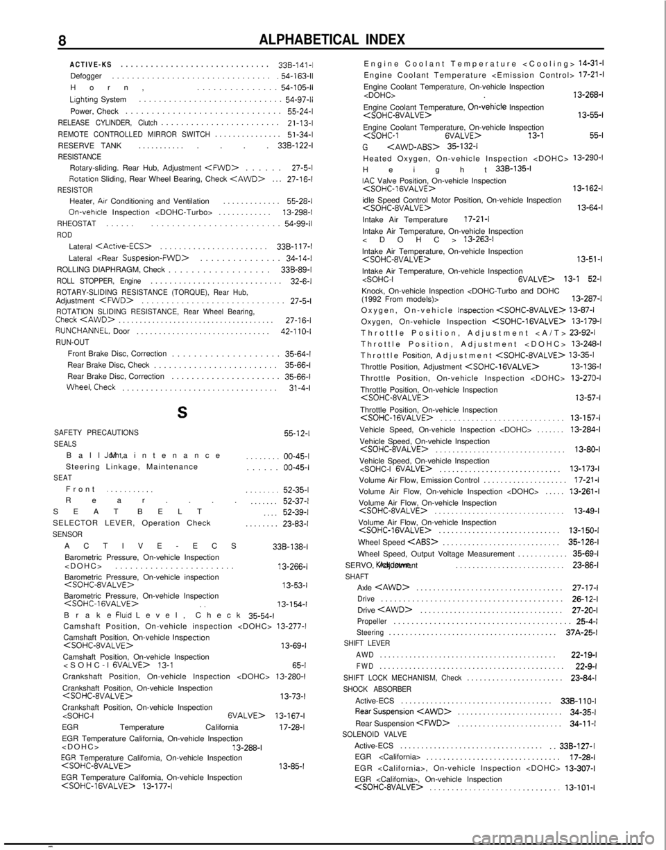
8ALPHABETICAL INDEX
ACTIVE-KS
.............................
.
338-l
41-1
Defogger ................................
.54-163-11
Horn
,
...............
54-105-11
Lightrng System............................
.
54-97-l)
Power, Check .............................. 55-24-l
RELEASE CYLINDER, Clutch.......................
.
21-13-l
REMOTE CONTROLLED MIRROR SWITCH..............
.
51-34-l
RESERVE TANK ............... 338-122-I
RESISTANCE
Rotary-sliding. Rear Hub, Adjustment
. 27-5-l
fiotation
Sliding, Rear Wheel Bearing, Check
.
27-16-l
RESISTOR
Heater, Arr Conditioning and Ventilation
............
. 55-28-l
On-vehicle
Inspection
RHEOSTAT.....
.
.........................
54-99-11
ROD
Lateral
.
338-l 17-l
Lateral
. 34-14-l
ROLLING DIAPHRAGM, Check .................. 338-89-I
ROLL STOPPER, Engine...........................
. 32-6-l
ROTARY-SLIDING RESISTANCE (TORQUE), Rear Hub,Adjustment
. 27-5-l
ROTATION SLIDING RESISTANCE, Rear Wheel Bearing,Check
. 27-16-l
RUNCHANNEL. Door
.............................
.
42-l 10-l
RUN-OUT
Front Brake Disc, Correction ...................
. 35-64-l
Rear Brake Disc, Check ......................... 35-66-l
Rear Brake Disc, Correction ...................... 35-66-i
WheeLCheck
................................. 31-4-I
S
SAFETY PRECAUTIONS
SEALS 55-12-l
Ball Joint, Maintenance
Steering Linkage, Maintenance
SEAT
Fron
t
.._........
Rear...
.
SEAT BELT
SELECTOR LEVER, Operation Check
SENSOR
........ 00-45-I
...... 00-45-I
........
52-35-l
....... 52-37-l
.... 52-39-l
........ 23-83-l
ACTIVE-ECS Barometric Pressure, On-vehicle Inspection
13-266-l
Barometric Pressure, On-vehicle inspection
Barometric Pressure, On-vehicle Inspection
Brake Fluld Level, Chec
k
35-54-l
Camshaft Position, On-vehicle inspection
Camshaft Position, On-vehicle Inspectron
13-69-l
Camshaft Position, On-vehicle Inspection
13-l
65-l
Crankshaft Position, On-vehicle Inspection
Crankshaft Position, On-vehicle Inspection
Crankshaft Position, On-vehicle Inspection
13-167-I
EGR Temperature California 17-28-l
EGR Temperature California, On-vehicle Inspection
EGR Temperature California, On-vehicle Inspection
13-85-l
EGR Temperature California, On-vehicle Inspection
Engine Coolant Temperature
Engine Coolant Temperature, On-vehicle Inspection
Engine Coolant Temperature, On-vehicle
Inspection
Engine Coolant Temperature, On-vehicle Inspection
13-l 55-l
G
Heated Oxygen, On-vehicle Inspection
Height 338-135-I
IAC Valve Position, On-vehicle Inspection
13-162-l
idle Speed Control Motor Position, On-vehicle Inspection
Intake Air Temperature 17-21-l
Intake Air Temperature, On-vehicle Inspection
Intake Air Temperature, On-vehicle Inspection
Intake Air Temperature, On-vehicle Inspection
13-l 52-l
Knock, On-vehicle Inspection
Oxygen, On-vehicle Inspection
Oxygen, On-vehicle Inspection
Throttle Position, Adjustment
>
Throttle Position, Adjustment
Throttle
Position, Adjustment
Throttle Position, Adjustment
Throttle Position, On-vehicle Inspection
13-287-1 13-87-l
13-179-l
23-92-l
13-248-l
13-35-l
13-136-I
13-270-I
Throttle Position, On-vehicle Inspection
Throttle Position, On-vehicle Inspection
. 13-157-l
Vehicle Speed, On-vehicle Inspection
Vehicle Speed, On-vehicle Inspection
. 13-80-I
Vehicle Speed, On-vehicle Inspection
.............................
13-l 73-l
Volume Air Flow, Emission Control ...................
.
17-21
-I
Volume Air Flow, On-vehicle Inspection
. 13-261-l
Volume Air Flow, On-vehicle Inspection
. 13-49-l
Volume Air Flow, On-vehicle Inspection
. 13-150-I
Wheel Speed
. 35-126-l
Wheel Speed, Output Voltage Measurement ............ 35-69-l
SERVO, Kickdown. Adjustment
.......................... 23-86-l
SHAFT
Axle
. 27-17-I
Drive........................................
. 26-12-I
Drive
. 27-20-I
Propeller.......................................
. 25-4-l
Steering.......................................
. 37A-25-l
SHIFT LEVER
AWD
.........................................
. 22-19-l
FWD
22-9-l
............................................
SHIFT LOCK MECHANISM, Check......................
. 23-84-l
SHOCK ABSORBER
Active-ECS
...................................
. 338-110-l
RearSuspension
. 34-35-l
Rear Suspension
.
34-l 1-ISOLENOID VALVE
Active-ECS
.................................
.
..33B-127- I
EGR
...............................
. 17-28-l
EGR
EGR