height adjustment MITSUBISHI GALANT 1989 Service Repair Manual
[x] Cancel search | Manufacturer: MITSUBISHI, Model Year: 1989, Model line: GALANT, Model: MITSUBISHI GALANT 1989Pages: 1273, PDF Size: 37.62 MB
Page 253 of 1273
FUEL SYSTEM
03R0297
Vapor hose
mmin.)Fillerhose
i2.l
B
3FOO7
A
1
Flare nut
Skure side
03Yo43
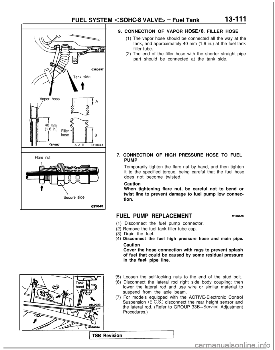
9. CONNECTION OF VAPOR HOSE/8. FILLER HOSE
(1) The vapor hose should be connected all the way at the tank, and approximately 40 mm (1.6 in.) at the fuel tank
filler tube.
(2) The end of the filler hose with the shorter straight pipe
part should be connected at the tank side.
7. CONNECTION OF HIGH PRESSURE HOSE TO FUEL PUMP
Temporarily tighten the flare nut by hand, and then tightenit to the specified torque, being careful that the fuel hose
does not become twisted.
Caution
When tightening flare nut, be careful not to bend or
twist line to prevent damage to fuel pump low connec-
tion.
FUEL PUMP REPLACEMENT
(1) Disconnect the fuel pump connector.
(2) Remove the fuel tank filler tube cap.
(3) Drain the fuel. MllGFAC
(4)
Disconnect the fuel high pressure hose and main pipe.
Caution
Cover the hose connection with rags to prevent splash
of fuel that could be caused by some residual pressure in the
fuel. pipe line.
(5) Loosen the self-locking nuts to the end of the stud bolt.
(6) Disconnect the lateral rod right side body coupling; then lower the lateral rod and use wire or similar material to
suspend from the axle beam.
(7) For models equipped with the ACTIVE-Electronic Control Suspension
(E.C.S.) disconnect the rear height sensor and
the lateral rod. (Refer to GROUP
33B-Service Adjustment
Procedures.)
Page 254 of 1273
13-112FUEL SYSTEM
03L0018
QcD ua .
CFa
cc
0c aa0u0aa
Positioning projection
03L0009
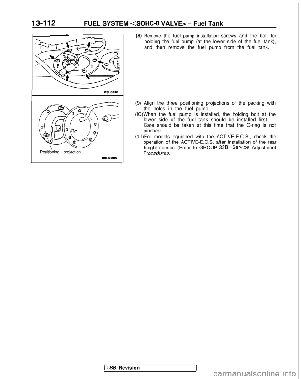
(8) Remove
the fuel pump installation screws and the bolt for
holding the fuel pump (at the lower side of the fuel tank),
and then remove the fuel pump from the fuel tank.
(9) Align the three positioning projections of the packing with the holes in the fuel pump.
(lO)When the fuel pump is installed, the holding bolt at the lower side of the fuel tank should be installed first.
Care should be taken at this time that the O-ring is not
pinched.
(1 l)For models equipped with the ACTIVE-E.C.S., check the operation of the ACTIVE-E.C.S. after installation of the rearheight sensor. (Refer to GROUP
33B-Service AdjustmentPrnrwiI irps II I ““VW-. W.S.,
1 TSB Revision
Page 462 of 1273
13-320FUEL SYSTEM
03RO297
V/apor hose
mmin.)
3FOO7
Filler
hoseB
A
\Secure side 03YO43
Ll
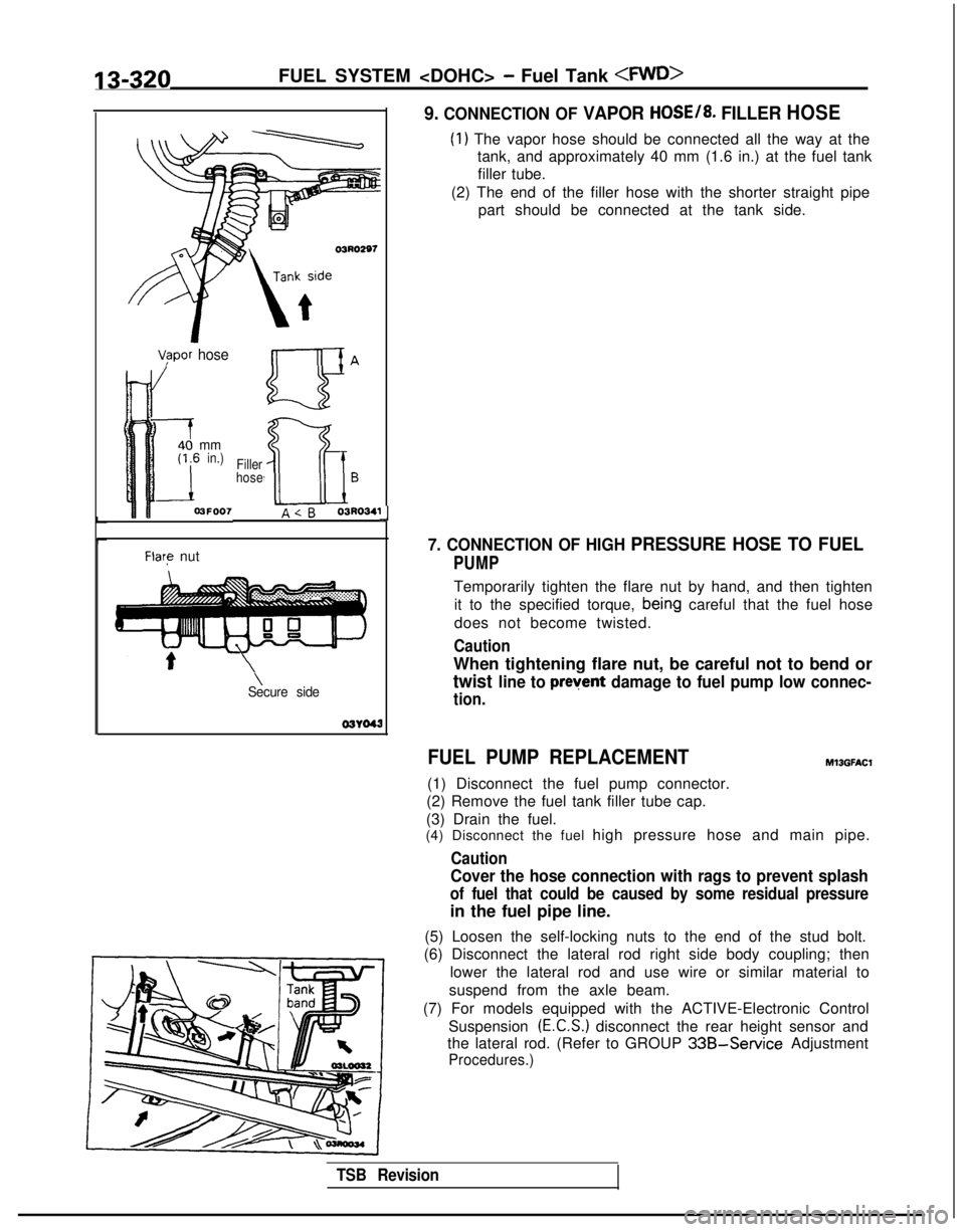
9. CONNECTION OF VAPOR HOSE/8. FILLER HOSE
(1) The vapor hose should be connected all the way at the
tank, and approximately 40 mm (1.6 in.) at the fuel tank
filler tube.
(2) The end of the filler hose with the shorter straight pipe part should be connected at the tank side.
7. CONNECTION OF HIGH PRESSURE HOSE TO FUEL
PUMP
Temporarily tighten the flare nut by hand, and then tighten
it to the specified torque,
bein,g careful that the fuel hose
does not become twisted.
Caution
When tightening flare nut, be careful not to bend or
twist line to prevent damage to fuel pump low connec-
tion.
FUEL PUMP REPLACEMENT
(1) Disconnect the fuel pump connector.
(2) Remove the fuel tank filler tube cap.
(3) Drain the fuel.
Ml3GFAt.X
(4) Disconnect the fuel high pressure hose and main pipe.
Caution
Cover the hose connection with rags to prevent splash
of fuel that could be caused by some residual pressure
in the fuel pipe line.
(5) Loosen the self-locking nuts to the end of the stud bolt.
(6) Disconnect the lateral rod right side body coupling; then
lower the lateral rod and use wire or similar material to
suspend from the axle beam.
(7) For models equipped with the ACTIVE-Electronic Control Suspension
(E.C.S.) disconnect the rear height sensor and
the lateral rod. (Refer to GROUP
33B-Service Adjustment
Procedures.)
TSB Revision
Page 463 of 1273
FUEL SYSTEM
I03LOO18
-
QGB ua \
a=
C-CT
0a
c oc3i20’0Qaa
Positidning projection
03L0000
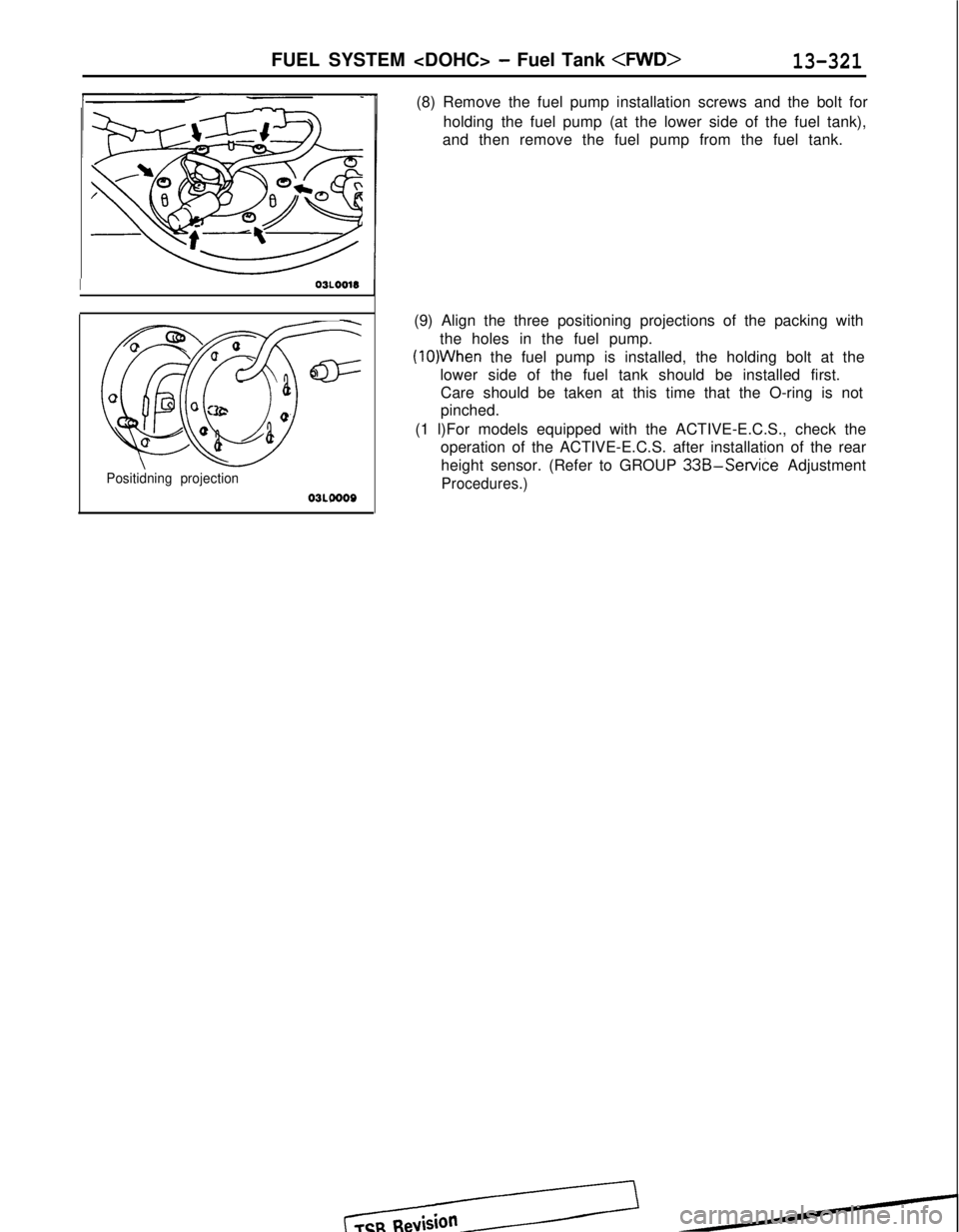
(8) Remove the fuel pump installation screws and the bolt for
holding the fuel pump (at the lower side of the fuel tank),
and then remove the fuel pump from the fuel tank.
(9) Align the three positioning projections of the packing with the holes in the fuel pump.
(lO)When the fuel pump is installed, the holding bolt at the
lower side of the fuel tank should be installed first. Care should be taken at this time that the O-ring is not
pinched.
(1 l)For models equipped with the ACTIVE-E.C.S., check the operation of the ACTIVE-E.C.S. after installation of the rear
height sensor. (Refer to GROUP
33B-Service Adjustment
Procedures.)
Page 655 of 1273
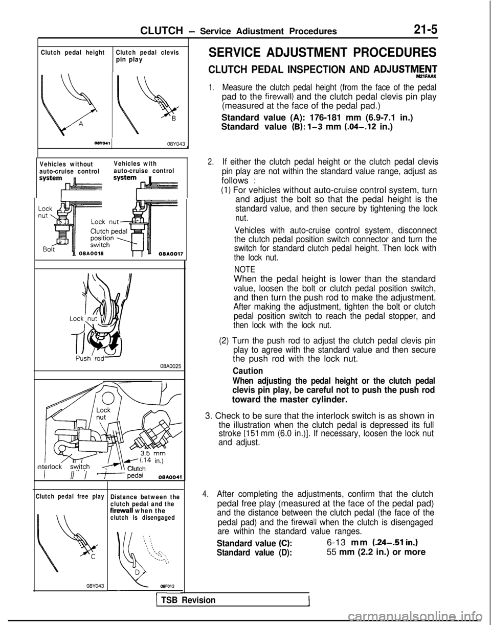
CLUTCH - Service Adiustment Procedures21-5
Clutch pedal height
Clutch pedal clevispin play
08104,08YO43
Vehicles without
auto-cruise control Vehicles with
auto-cruise control
08A0025
IL\\A- i.14
in.)Nnt,erlock s.y,ityh ,
Clutch
II/ / ?--pedal08AOO41
Clutch pedal free play
08YO43
Distance between the
clutch pedal and the
firewall when theclutch is disengaged
‘5 :: :
*\\\ ;.,
\.
.-‘.* ..,.--. . .:,
eir-
.;
D
l3sFO13
SERVICE ADJUSTMENT PROCEDURES
CLUTCH PEDAL INSPECTION AND ADJUSTM&‘+d+d
1.Measure the clutch pedal height (from the face of the pedal
pad to the firewall) and the clutch pedal clevis pin play
(measured at the face of the pedal pad.)
Standard value (A): 176-181 mm (6.9-7.1 in.)
Standard value
(B): l-3 mm (.04-.12
in.)
2.If either the clutch pedal height or the clutch pedal clevis
pin play are not within the standard value range, adjust as
follows :
(1) For vehicles without auto-cruise control system, turn and adjust the bolt so that the pedal height is the
standard value, and then secure by tightening the lock
nut.
Vehicles with auto-cruise control system, disconnect
the clutch pedal position switch connector and turn the
switch for standard clutch pedal height. Then lock with
the lock nut.
NOTE
When the pedal height is lower than the standard
value, loosen the bolt or clutch pedal position switch,
and then turn the push rod to make the adjustment.
After making the adjustment, tighten the bolt or clutch
pedal position switch to reach the pedal stopper, and
then lock with the lock nut.
(2) Turn the push rod to adjust the clutch pedal clevis pin play to agree with the standard value and then secure
the push rod with the lock nut.
Caution
When adjusting the pedal height or the clutch pedal
clevis pin play, be careful not to push the push rod
toward the master cylinder.
3. Check to be sure that the interlock switch is as shown in
the illustration when the clutch pedal is depressed its full
stroke
[I51 mm (6.0 in.)]. If necessary, loosen the lock nut
and adjust.
4.After completing the adjustments, confirm that the clutch
pedal free play (measured at the face of the pedal pad)
and the distance between the clutch pedal (the face of the
pedal pad) and the
firewall when the clutch is disengaged
are within the standard value ranges.
Standard value (C):6-13 mm (.24--51 in.)
Standard value (D):55 mm (2.2 in.) or more
1 TSB Revision
Page 889 of 1273
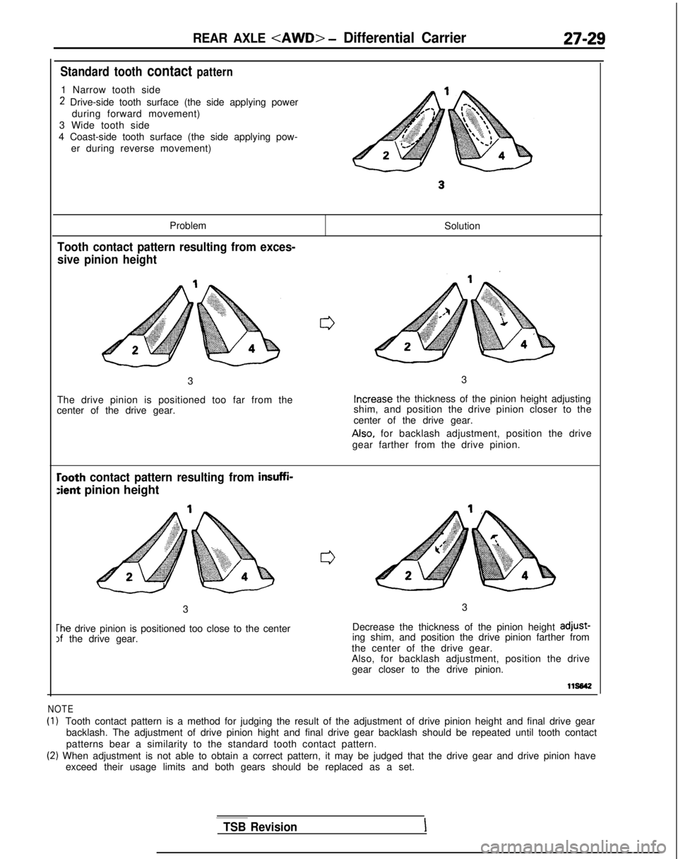
REAR AXLE
Standard tooth contact pattern
1 Narrow tooth side
2 Drive-side tooth surface (the side applying powerduring forward movement)
3 Wide tooth side
4 Coast-side tooth surface (the side applying pow- er during reverse movement)
Problem
Tooth contact pattern resulting from exces-
sive pinion height
Solution
3
The drive pinion is positioned too far from the
center of the drive gear. 3Increase
the thickness of the pinion height adjusting
shim, and position the drive pinion closer to the
center of the drive gear. Also,
for backlash adjustment, position the drive
gear farther from the drive pinion.
rooth contact pattern resulting from insuffi-
:ient pinion height
3
The drive pinion is positioned too close to the centerIf the drive gear. 3
Decrease the thickness of the pinion height adjust-
ing shim, and position the drive pinion farther from
the center of the drive gear.
Also, for backlash adjustment, position the drive gear closer to the drive pinion.
lls642
NOTE
(1)Tooth contact pattern is a method for judging the result of the adjustme\
nt of drive pinion height and final drive gear
backlash. The adjustment of drive pinion hight and final drive gear back\
lash should be repeated until tooth contact
patterns bear a similarity to the standard tooth contact pattern.
(2) When adjustment is not able to obtain a correct pattern, it may be judg\
ed that the drive gear and drive pinion have exceed their usage limits and both gears should be replaced as a set.
TSB RevisionI
Page 890 of 1273
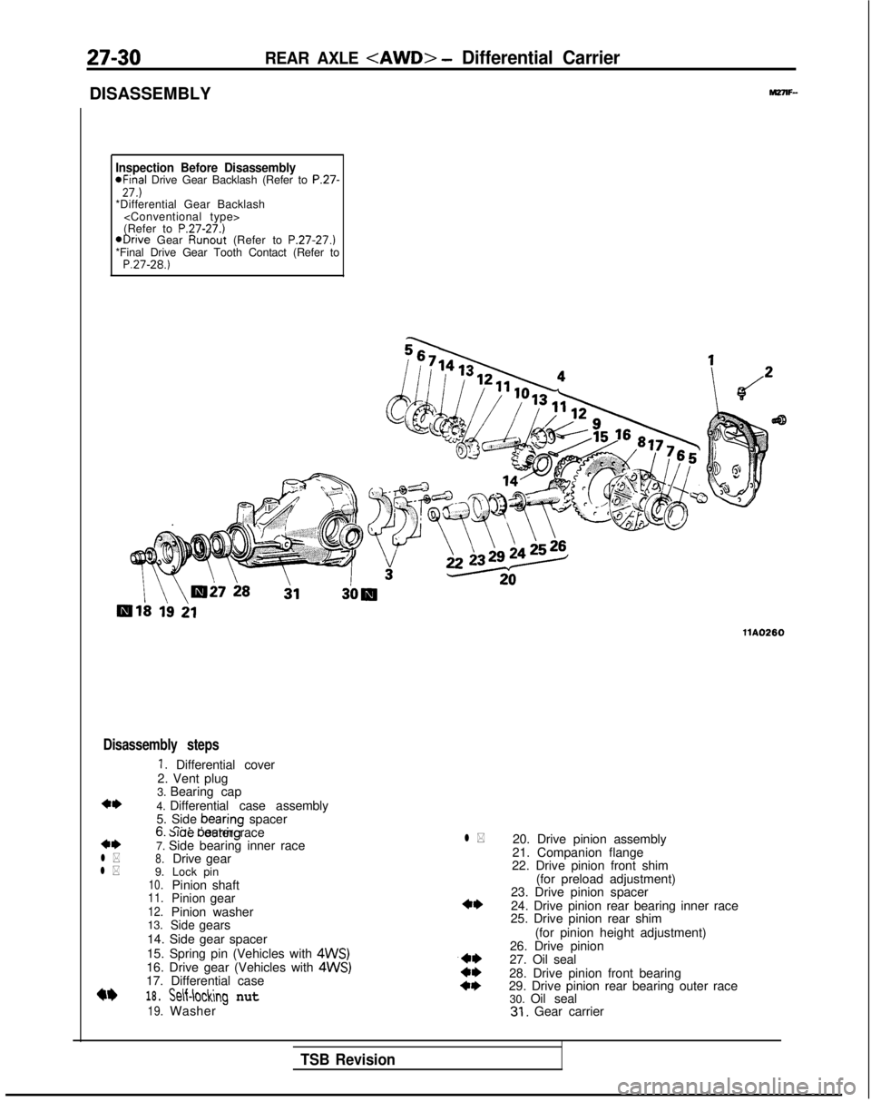
27-30
DISASSEMBLY
REAR AXLE
Inspection Before Disassembly*Final Drive Gear Backlash (Refer to P.27-27.)*Differential Gear Backlash
(Refer to
P.27-27.)@Drive Gear Runout
(Refer to P.27-27.)
*Final Drive Gear Tooth Contact (Refer to
P.27-28.)
llA0260
Disassembly steps
1. Differential cover
2. Vent plug
**l *
l *
3. Bearing cap
4. Differential case assembly
5. Side bearing
spacer
n n.* I0. slae oeanng outer race
7. Side bearing inner race
8.Drive
9. gear
10.Lock pin
Pinion shaft
11.Pinion12.gear
Pinion washer
13.
Sidegears
14. Side gear spacer
15. Spring pin (Vehicles with
4WS)16. Drive gear (Vehicles with 4WS)17. Differential case
18.
19.
Self-loclhg nut
Washer
l *20. Drive pinion assembly
21. Companion flange
22. Drive pinion front shim
(for preload adjustment)
23. Drive pinion spacer
24. Drive pinion rear bearing inner race
25. Drive pinion rear shim
(for pinion height adjustment)
26. Drive pinion
27. Oil seal
28. Drive pinion front bearing
29. Drive pinion rear bearing outer race 30. Oil seal
31. Gear carrier
TSB Revision
Page 893 of 1273
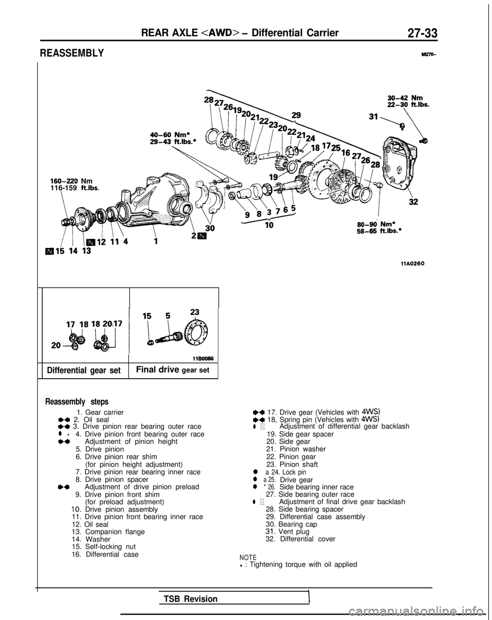
REASSEMBLY
REAR AXLE
M27n-
160-220
Nm
116-159
ft.lbs.
Differential gear set
11BOO66
Final drive gear set
Reassembly steps
1. Gear carrier*a 2. Oil seal++ 3. Drive pinion rear bearing outer racel +4. Drive pinion front bearing outer race*aAdjustment of pinion height
5. Drive pinion
6. Drive pinion rear shim (for pinion height adjustment)
7. Drive pinion rear bearing inner race
8. Drive pinion spacer
*aAdjustment of drive pinion preload
9. Drive pinion front shim (for preload adjustment)
10. Drive pinion assembly
11. Drive pinion front bearing inner race
12. Oil seal
13. Companion flange
14. Washer 15. Self-locking nut
16. Differential case so-9d
Nm*
5845
ft.lbs.*
llA0260
~~ 17. Drive gear (Vehicles with 4WS)e+ 18, Spring pin (Vehicles with 4WS)l *Adjustment of differential gear backlash
19. Side gear spacer
20. Side gear
21. Pinion washer
22. Pinion gear
23. Pinion shaft
l a 24. Lock pinl a 25.Drive gearl * 26.Side bearing inner race
27. Side bearing outer race
l *Adjustment of final drive gear backlash
28. Side bearing spacer 29. Differential case assembly
30. Bearing cap
31. Vent plug
32. Differential cover
NOTEl : Tightening torque with oil applied
TSB RevisionI
Page 895 of 1273
REAR AXLE
IllK610
90938-o 1
llY181
llY182
MB990905-4-C
MIT216335
MIT216336
MB990905-2-01
u-
MB990905l-01
llW616
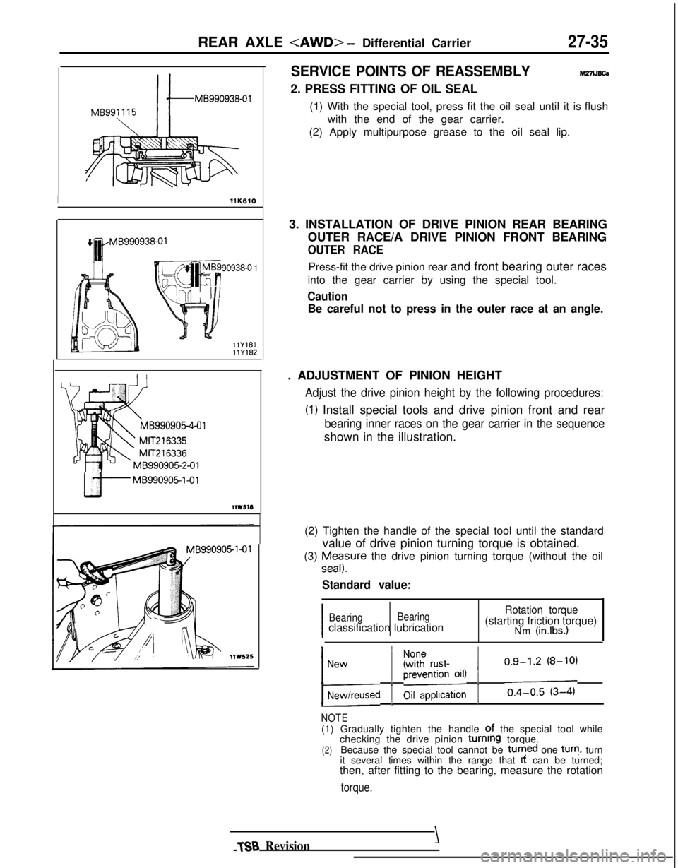
SERVICE POINTS OF REASSEMBLYM27lJ6c6
2. PRESS FITTING OF OIL SEAL
(1) With the special tool, press fit the oil seal until it iswith the end of the gear carrier.
(2) Apply multipurpose grease to the oil seal lip. flush
3. INSTALLATION OF DRIVE PINION REAR BEARING OUTER RACE/A DRIVE PINION FRONT BEARING
OUTER RACE
Press-fit the drive pinion rear and front bearing outer races
into the gear carrier by using the special tool.
Caution
Be careful not to press in the outer race at an angle.
. ADJUSTMENT OF PINION HEIGHT
Adjust the drive pinion height by the following procedures: (I)
Install special tools and drive pinion front and rear
bearing inner races on the gear carrier in the sequence
shown in the illustration.
(2) Tighten the handle of the special tool until the standard value of drive pinion turning torque is obtained.
(3)
Ea;sure the drive pinion turning torque (without the oil
Standard value:
I I
Bearing BearingRotation torque
classification lubrication (starting friction torque)
Nm (in.lbs.)
I,;,r,used 1 EJi!x%;; 1/;;;;y;-;
NOTE(1) Gradually tighten the handle ?f the special tool while
checking the drive pinion turning torque.(2)Because the special tool cannot be turqed one tur?,
turn
it several times within the range that It
can be turned;
then, after fitting to the bearing, measure the rotation
torque.
TSB Revision\
Page 940 of 1273
339-l
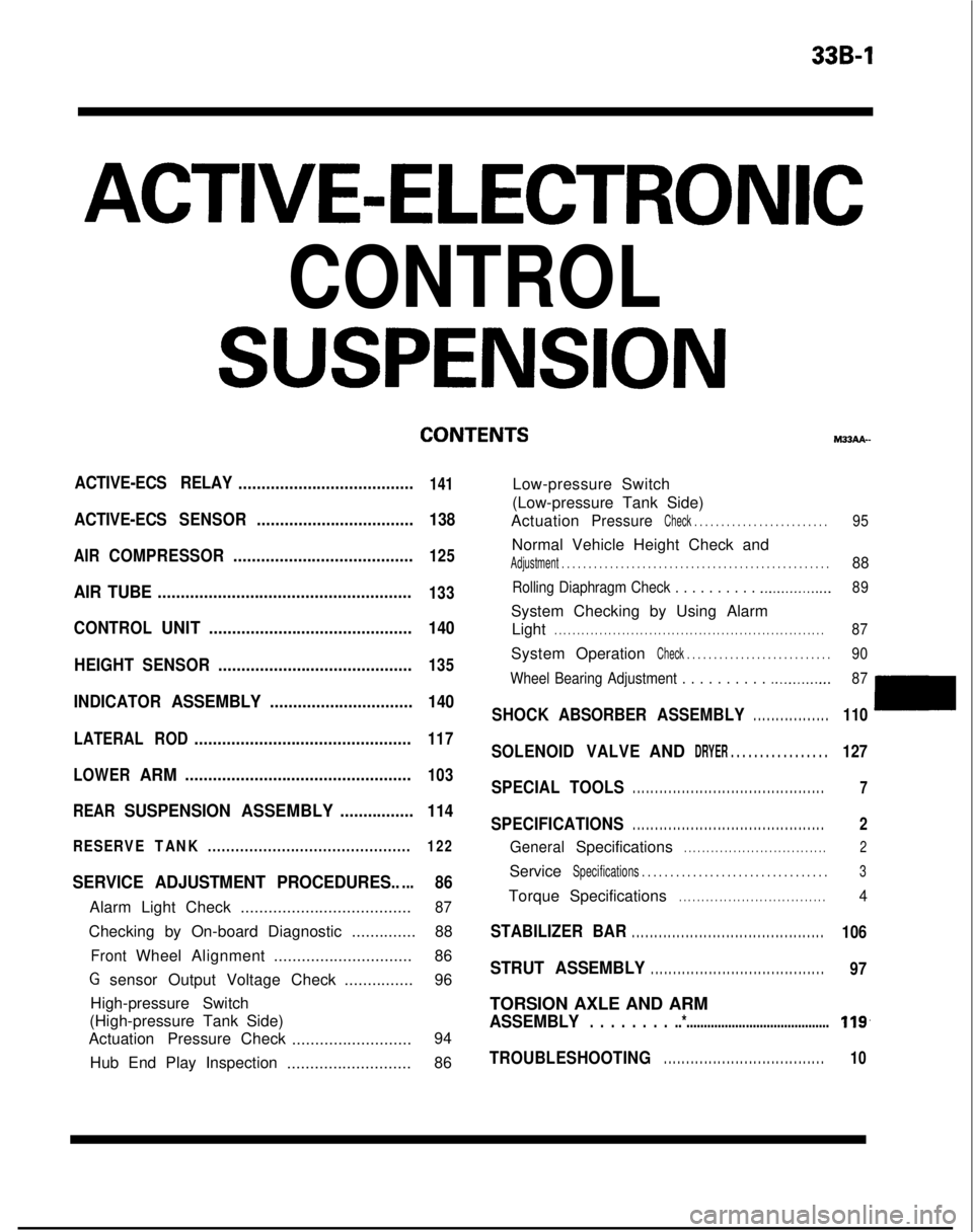
ACTIVE-ELECTRONIC
CONTROL
SUSPENSION
ACTIVE-ECS RELAY......................................141
ACTIVE-ECSSENSOR.................................. 138
AIRCOMPRESSOR.......................................125
AIR TUBE.......................................................133
CONTROLUNIT............................................ 140
HEIGHT SENSOR ..........................................
135
INDICATORASSEMBLY............................... 140
LATERALROD...............................................117
LOWER
ARM.................................................103
REAR
SUSPENSION ASSEMBLY................114
RESERVETANK............................................ 122
SERVICE ADJUSTMENT PROCEDURES.....86
Alarm Light Check.....................................87
Checking by On-board Diagnostic ..............88
FrontWheelAlignment .............................. 86
G sensor Output Voltage Check ...............96
High-pressure Switch
(High-pressure Tank Side)
Actuation Pressure Check
.......................... 94
Hub End Play Inspection ...........................86 M33AA-
Low-pressure Switch
(Low-pressure Tank Side)
Actuation
PressureCheck . . . . . . . . . . . . . . . . . . . . . . . . .95
Normal Vehicle Height Check and
Adjustment . . . . . . . . . . . . . . . . . . . . . . . . . . . . . . .\
. . . . . . . . . . . . . . . . . . .88
Rolling Diaphragm Check . . . . . . . . . . .._.............. 89
System Checking by Using Alarm
Light
. . . . . . . . . . . . . . . . . . . . . . . . . . . . . . . . . . . . \
. . . . . . . . . . . . . . . . . . . . . . . .87
System OperationCheck . . . . . . . . . . . . . . . . . . . . . . . . . . .90
Wheel Bearing Adjustment . . . . . . . . . .
.._........... 87
SHOCKABSORBER ASSEMBLY. . . . . . . . . . . . . . . . .110
SOLENOIDVALVEANDDRYER . . . . . . . . . . . . . . . . .127
SPECIAL TOOLS. . . . . . . . . . . . . . . . . . . . . . . . . . . . . . . . . . . . \
. . . . . . .7
SPECIFICATIONS. . . . . . . . . . . . . . . . . . . . . . . . . . . . . . . . . . . . \
. . . . . . .2
GeneralSpecifications. . . . . . . . . . . . . . . . . . . . . . . . . . . . . . . .2
ServiceSpecifications . . . . . . . . . . . . . . . . . . . . . . . . . . . . .\
. . . .3
TorqueSpecifications. . . . . . . . . . . . . . . . . . . . . . . . . . . . . . . . .4
STABILIZER BAR. . . . . . . . . . . . . . . . . . . . . . . . . . . . . . . . . . . . \
. . . . . . .106
STRUT ASSEMBLY. . . . . . . . . . . . . . . . . . . . . . . . . . . . . . . . . . . . \
. . .97
TORSION AXLE AND ARM
ASSEMBLY. . . . . . . . ..*.........................................119,
TROUBLESHOOTING. . . . . . . . . . . . . . . . . . . . . . . . . . . . . . . . . . . .10