instrument panel MITSUBISHI GALANT 1989 Service User Guide
[x] Cancel search | Manufacturer: MITSUBISHI, Model Year: 1989, Model line: GALANT, Model: MITSUBISHI GALANT 1989Pages: 1273, PDF Size: 37.62 MB
Page 1143 of 1273
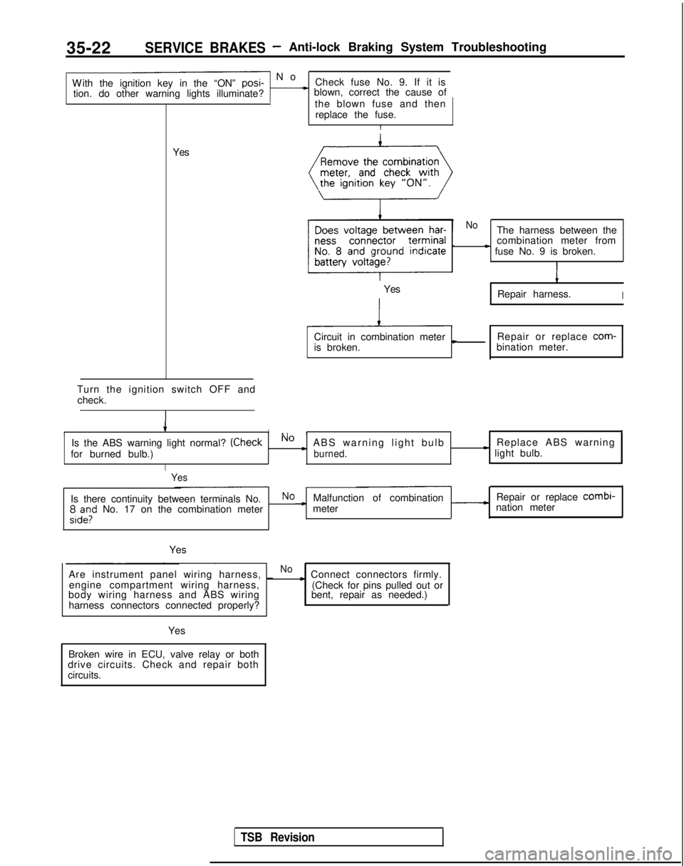
35-22SERVICE BRAKES- Anti-lock Braking System Troubleshooting
- N
o
With the ignition key in the “ON” posi-
Check fuse No. 9. If it is
tion. do other warning lights illuminate?
* blown, correct the cause of
the blown fuse and thenreplace the fuse.
I
Yes
Turn the ignition switch OFF and check.
4II., III,
Is the ABS warning light normal? (CheckNo cABS warning light bulb Replace ABS warning
for burned bulb.)burned.* light bulb.
I
Yes
NoThe harness between the
combination meter from
* fuse No. 9 is broken.
1
Repair harness.I
Circuit in combination metercRepair or replace com-
is broken. bination meter.
Yes
Is there continuity between terminals No.NoMalfunction of combination Repair or replace combi-
;,d”,l” No. 17 on the combination meter -meter
nation meter
Yes
Are instrument panel wiring harness, _
Noc Connect connectors firmly.
engine compartment wiring harness,
body wiring harness and ABS wiring
harness connectors connected properly? (Check for pins pulled out or
bent, repair as needed.)
Yes
Broken wire in ECU, valve relay or both
drive circuits. Check and repair both
circuits.
TSB Revision
Page 1161 of 1273
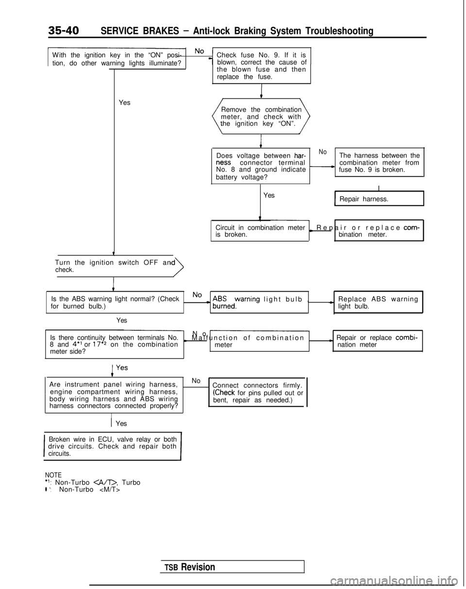
SERVICE BRAKES - Anti-lock Braking System Troubleshooting
W
ith the ignition key in the “ON” posi- No
Check fuse No. 9. If it is
tion, do other warning lights illuminate? blown, correct the cause of
-T-
Yesthe blown fuse and then
replace the fuse.I
Remove the combination
meter, and check with
the ignition key “ON”.
I
Does voltage between har-NoThe harness between the ness
connector terminal
No. 8 and ground indicate
-combination meter from
fuse No. 9 is broken.
battery voltage?
I
Yes Repair harness.
Circuit in combination meter
is broken.
L Repair or replace com-
bination meter.
Turn the ignition switch OFF an
check.
I
Is the ABS warning light normal? (CheckNo
for burned bulb.)c A$Eedyrning light bulb
,
c Replace ABS warning
light bulb.
Yes
Is there continuity between terminals No. No -
8 and 4” or 17’2 on the combinationI Malfunction of combinatio
n
meter
I Repair or replace combi-
meter side? nation meter
Are instrument panel wiring harness, No
-~
engine compartment wiring harness, . Connect connectors firmly.
body wiring harness and ABS wiring
(Check for pins pulled out or
harness connectors connected properly? bent, repair as needed.)
I
1 Yes
I
Broken wire in ECU, valve relay or both
drive circuits. Check and repair both
circuits.
I
NOTE‘1: Non-Turbo . Turbol *:Non-Turbo
TSB Revision
Page 1197 of 1273
35-76SERVICE BRAKES - Brake Pedal
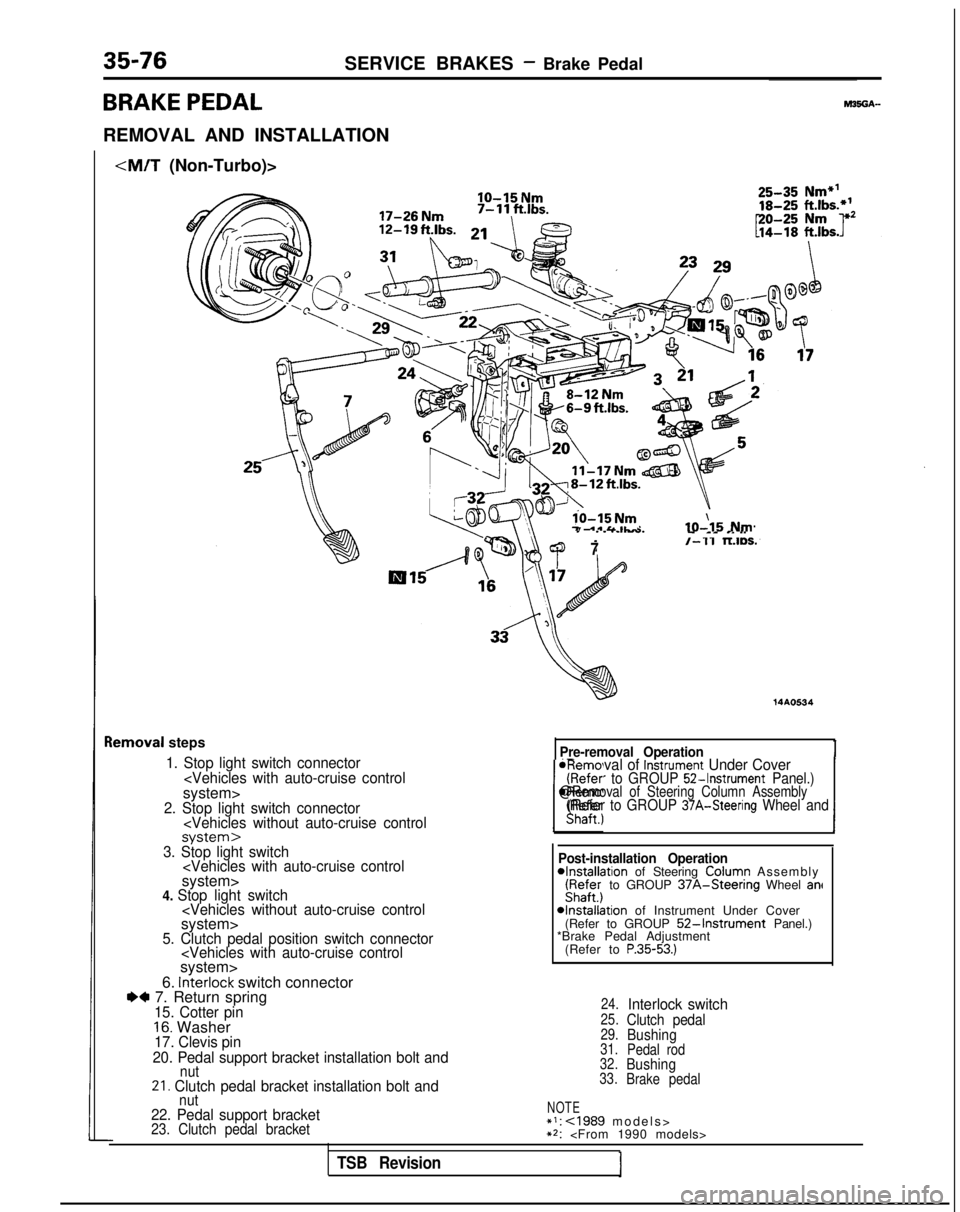
BRAKE PEDAL
REMOVAL AND INSTALLATION
IO-15 Nm
lo-15 Nm7 .*&&IL-IO-\15 Nm
lemoval
steps
1. Stop light switch connector
7/-11 TLIDS.
14AO534
Pre-removal Operation
*Removal of Instrument Under Cover(Refer to GROUP 52-Instrument Panel.)
IShaft., 1
@Removal of Steering Column Assembly(Refer to GROUP 37A-Steering Wheel and
-I---.3. Stop light switch
6. interlock switch connectorI)* 7. Return spring15. Cotter pin16. Washer17. Clevis pin
20. Pedal support bracket installation bolt and
nut21. Clutch pedal bracket installation bolt and Post-installation Operation
4nstallation of Steering ColuFn Assembl
y
iyafe;j to GROUP 37A-Steenng Wheel ant
4nstallation of Instrument Under Cover
(Refer to GROUP 52-Instrument Panel.)
*Brake Pedal Adjustment
(Refer to
P.35-53.)
24.Interlock switch25.Clutch pedal29.Bushing31. Pedal rod
32.Bushing33. Brake pedal
nut22. Pedal support bracketNOTE*I: cl989 models
>
23. Clutch pedal bracket**:
TSB Revision
Page 1198 of 1273
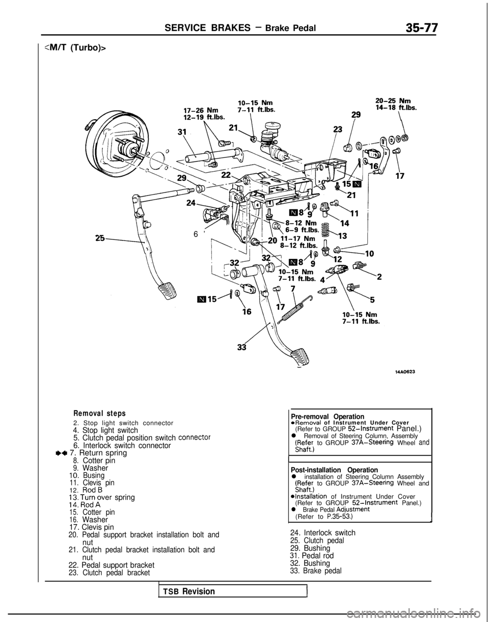
SERVICE BRAKES - Brake Pedal35-77
:M/T (Turbo)>
lo-15 Nm20-25 Nm
17-26 Nm7-11
ftlbs. 14-18
ft.lbs.
12-19. ft.lbs.I?9\ a-
6’
Removal steps
2. Stop light switch connector4. Stop light switch
5. Clutch pedal position switch connector
6. Interlock switch connectorI)+ 7. Return spring8.Cotter pin9.Washer10.Busing11.Clevis pin12.RodB; 2: ‘,l%;rer spring
15.Cotter pin16.Washer
17. Clevis pin
20. Pedal support bracket installation bolt andnut21. Clutch pedal bracket installation bolt andnut
22. Pedal support bracket
23. Clutch pedal bracket
- 14AO623
Pre-removal Operation
*Removal
of Instrument Under Cover
(Refer to GROUP
52-Instrument Panel.)
l Removal of Steering Column, Assembly r;affer)
to GROUP
37A-Steenng Wheeland
I
Post-installation Operationl installation of Steering Column Assembly(Fyaffer) to GROUP 37A-Steenng Wheel and
*Installation of Instrument Under Cover
(Refer to GROUP 52-Instrument Panel.)l Brake Pedal Adiustment
(Refer to P.35-53.)1
24. Interlock switch25. Clutch pedal29. Bushing31. Pedal rod
32. Bushing
33. Brake pedal
TSB RevisionI
Page 1266 of 1273

ALPHABETICAL INDEX5
Fuel, Maintenance.
.
Power Steering
Transaxle
011 Cooler
Vacuum
..,...,..,.......
Water
Water
Water
HUB
End Play inspection
End Play, Inspection
Front Axl
e
Rear Axle
Rear Axle
HYDRAULIC UNIT
HYDRAULIC UNIT, Inspection
I 00-39-I
37A-58-I
23-l
00-l
17-4-I
14-26-I
14-28-l
14-23-l
338-86-I
26-5-l
26-l-l
27-8-l
27-6-1
35-121-l
35-70-t
IAC VALVE POSITION SENSOR, On-vehicle Inspection
.
13-162-l
IDLE AIR CONTROL MOTOR
DC Motor,
On-vehicle
Inspection
13-184-I
Stepper Motor, On-vehicle Inspection
IDLE SPEED
Basic, Adjustment
.....................
.
13-245-l
Basic, Adjustment
.
13-33-l
Basrc. Adjustment
.
13-133-l
Curb, Inspection
...... 13-245-I
Curb, Inspection
.
...
...........
.
13-32-I
Curb, Inspection
.
13-133-I
IDLE SPEED CONTROL MOTOR (DC Motor),
On-vehrcle Inspectron
.
13-93-l
IDLE SPEED CONTROL MOTOR POSITION SENSOR,On-vehicle Inspection
.
13-64-I
IDLE-UP OPERATION, Check ....................... 55-24-l
IGNITION COIL
On-vehtcle
Inspection
On-vehicle
Inspectron
.
13-96-l
On-vehicle
Inspection
.
13-186-I
IGNITION POWER TRANSISTOR
On-vehrcle
Inspection
On-vehicle Inspection
On-vehicle
inspection
.
13-186-l
IGNITION SWITCH
Chassis Electrical.
...........................
.
.....
54-6-11
On-vehicle Inspection
.
13-284-l
On-vehicle Inspection
... 13-78-l
On-vehicle Inspection
On-vehicle Inspection
On-vehicle inspection
.
13-171 -IIGNITION SYSTEM...........................
.
16-32-11.....
.
IGNITION TIMING Adjustment
16-40-11
Adjustment
.
....................
INDICATOR...........................
.
.......... 33B-140-l
INDIVIDUAL PARTS, Auto-cruise Control, Inspection .......
13-401 -I
INFLATION PRESSURE, Tire, Check......................
.
31-4-l
INJECTORS
On-vehicle Inspection
..................
.
13-295-I
On-vehicle Inspection
.
13-90-I
On-vehicle Inspection
........... 13-l
81-l
INSTRUMENT PANEL ................................. 52-22-l
INTAKE AIR TEMPERATURE SENSOR
Emission Control
..............................
.
17-21 -I
On-vehicle inspection
.................
.
13-263-l
On-vehicle Inspection
.
13-51-IOn-vehicle Inspection
INTAKE CHARGE PRESSURE CONTROL SYSTEM,Inspection . . . . . . . . . . . . . . .
INTAKE MANIFOLD
DOHC
,.. . . . . . . . . . . ,,... SOHC-WALVE
SOHC-l
GVALVE
K
KEY INTERLOCK MECHANISM, Check
.
KICKDOWN SERVO, Adjustment
KNOCK SENSOR, On-vehicle Inspection
KNUCKL
E
L
LASH ADJUSTERS
Check
>
Check
LATCHDoor, Fron
t
Door, Rear
LATERAL ROD
Active-EC
S
Rear Suspesion
LEAK, Refrrgerant. Repair Procedure
LEVELFluid, Transaxle, Inspection
Oil, Transfer, Inspection.
LEVERParking Brak
e
Parking Brake, Stroke Check
Selector, Operation Check.
Shift
Shift
LIDTrunk ._, . . . . . . . . . . . . .
Trunk, Adjustmen
t
LIGHT
......
......
......
.....
......
......
.....
......
......
......
......
......
......
......
......
......
......
......
......
......
.......
........
.......
........
........
........
........
........
........
........
........
........
........
........
........
........
........
Alarm, Chec
k
Rear Combination
Stop, High Mounted
LIGHTING SYSTEM
LINEBrake
Fuel
Fuel
Fuel
Fuel
Refrigerant
.
Vapor
Vapor
Vapor
Vapor
LINE PRESSURE, Adjustment
LININGBrake, Thickness Check.
Rear Drum Brake, Maintenance
LOOSE PANE
L
LOWER ARMActive-KS
Front Suspensio
n
Rear Suspesion
........
...............
.......
........
........
........
........
........
........
........
........
.........
.........
.........
.........
.........
........ 13-152-I
15-7-l
15-21 -I
15-14-I
15-18-I
23-83-1
23-86-i
13-287-l
26-6-l
11-57-1
1 l-7-l
42-96-l
42-99-l
338-l 17-l
34-14-I
’
55-21-I
23-82-l
23-82-l
36-4-l
36-2-l
23-83-l
22-19-l
22-9-l
42-57-l
42-50-I
338-87-I
54-95-11
54-96-11
54-38-11
35-87-I
13-326-I
13-324-I
13-113-I
13-I
95-l
55-54-l
13-326-I
13-324-l
13-I 13-l
13-195-1
23-88-l
35-67-l
00-44-I
42-62-i
338-l
03-l
33A-10-I
34-28-l
Page 1271 of 1273