parking brake MITSUBISHI GALANT 1989 Service User Guide
[x] Cancel search | Manufacturer: MITSUBISHI, Model Year: 1989, Model line: GALANT, Model: MITSUBISHI GALANT 1989Pages: 1273, PDF Size: 37.62 MB
Page 877 of 1273
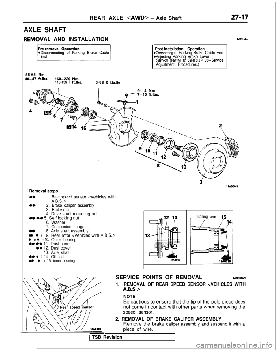
REAR AXLE
AXLE SHAFT
IEMOVAL
AND INSTALLATION
55-65
Nm 40-47
ftlbs.160-220NmI116-159
Ift.lbs.36-43 50-60ft.lbs. Nm
Post-installation OperationKonnecting of Parking Brake Cable End@Adjusting Parking Brake LeverStroke (Refer to GROUP 36-Service
Adjustment Procedures.)
9-14 Nmq------7-10 ft.lbs.
llA0041
Removal steps
4*1. ifsa.yyed sensor
arm 15
SERVICE POINTS OF REMOVAL
MmwAN
1.REMOVAL OF REAR SPEED SENSOR
NOTE
Be cautious to ensure that the tip of the pole piece does
not come in contact with other parts
when removing the
speed sensor.
2. REMOVAL OF BRAKE CALIPER ASSEMBLY
Remove the brake caliper assembly and suspend it with a
piece of wire.
I- _,1 TSB RevisionI
Page 1053 of 1273
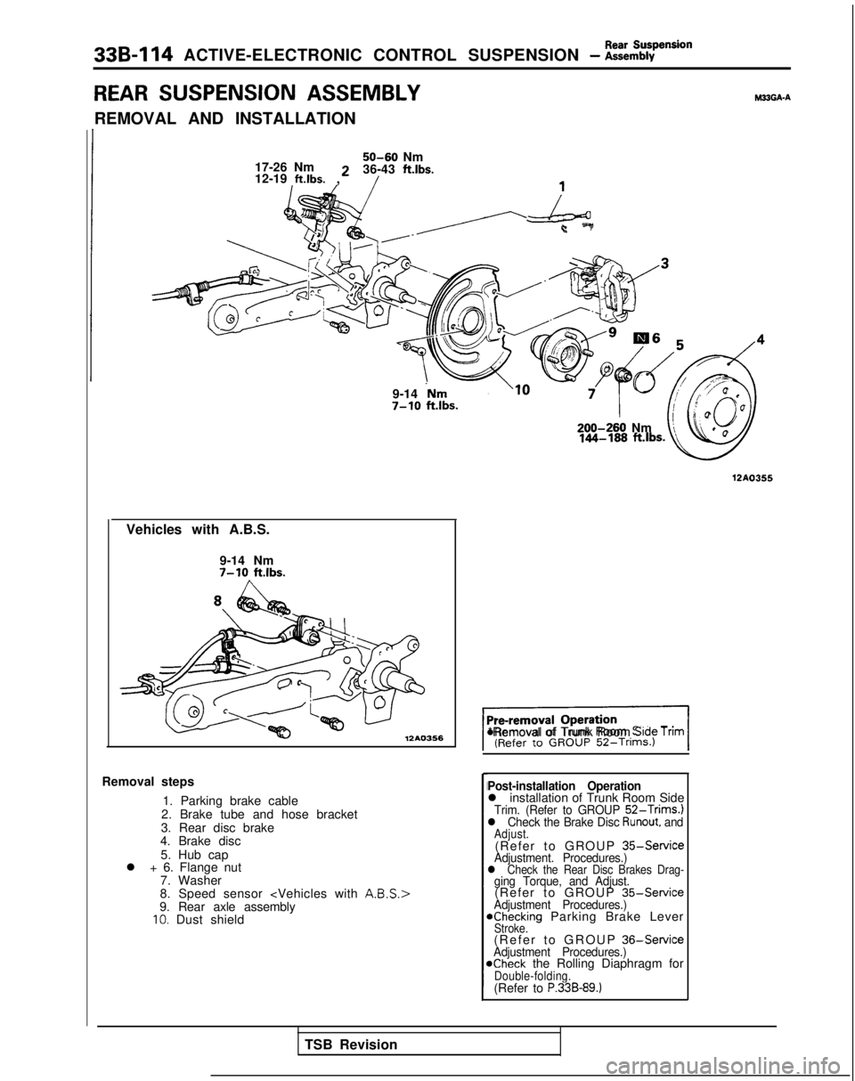
33B-114 ACTIVE-ELECTRONIC CONTROL SUSPENSION - ~:h%pension
REAR SUSPENSION ASSEMBLYM33GA-A
REMOVAL AND INSTALLATION
50-60 Nm
17-26 Nm 36-43 ftlbs.
12-19
ft.lbs. 2
,
9-14
‘Nm7-10 ftlbs.
Vehicles with A.B.S. 9-14 Nm
7-10 ft.lbs.
12A0366
Removal steps1. Parking brake cable
2. Brake tube and hose bracket
3. Rear disc brake
4. Brake disc
5. Hub cap
l + 6. Flange nut
7. Washer
8. Speed sensor
9. Rear axle assembly
10. Dust shield 200-260
Nm
12A0355
%I*Removal of Trunk Room Srde Tnm
Post-installation Operationl installation of Trunk Room SideTrim. (Refer to GROUP 52-Trims.)l Check the Brake Disc Runout, andAdjust.(Refer to GROUP
35-ServiceAdjustment. Procedures.)l Check the Rear Disc Brakes Drag-ging Torque, and Adjust.(Refer to GROUP
35-ServiceAdjustment Procedures.)achecking Parking Brake LeverStroke.(Refer to GROUP
36-ServiceAdjustment Procedures.)@Check the Rolling Diaphragm forDouble-folding.(Refer to P.33B-89.)
TSB Revision
Page 1058 of 1273
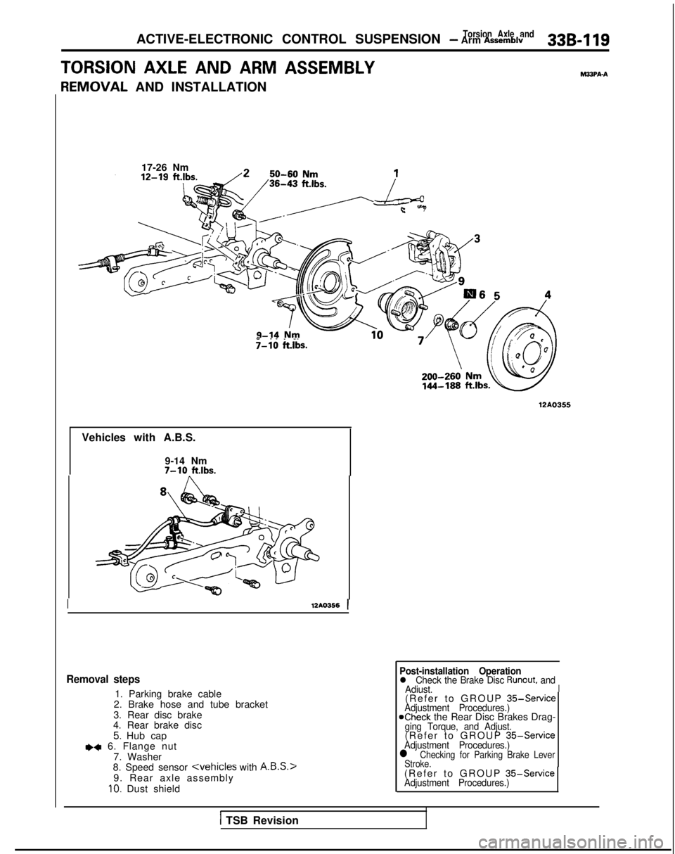
Torsion Axle andACTIVE-ELECTRONIC CONTROL SUSPENSION - Arm Assemblv33B-119
TORSION AXLE AND ARM ASSEMBLYMSPA-A
F
{EMOVAL
AND INSTALLATION
17-26 Nm
._. _.T-10 ftlbs.
12AO355
Vehicles with A.B.S.
9-14 Nm
7-10 ftlbs.
I
12AO356
1
Removal steps
1. Parking brake cable
2. Brake hose and tube bracket
3. Rear disc brake
4. Rear brake disc
5. Hub capea 6. Flange nut
7. Washer
8. Speed sensor
y
IO. Dust shield
1 TSB Revision
Post-installation Operationl Check the Brake Disc Runout, and
Adiust.I(Refer to GROUP 35-ServiceAdjustment Procedures.)
NIheck
the Rear Disc Brakes Drag-
ging Torque, and Adjust.(Refer to GROUP 35-ServiceAdjustment Procedures.)l Checking for Parking Brake Lever
Stroke.
(Refer to GROUP 35-ServiceAdjustment Procedures.)
Page 1087 of 1273
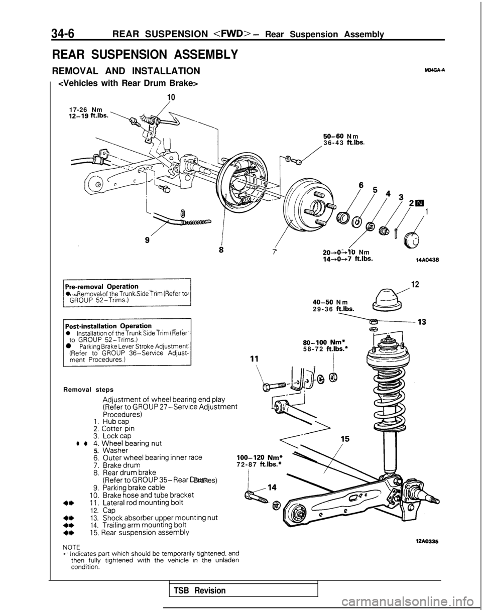
34-6REAR SUSPENSION
- Rear Suspension Assembly
REAR SUSPENSION ASSEMBLY
REMOVAL AND INSTALLATION
10
17-26 Nm
12-19 “‘“s. y+.,
6 54 32w
dy4d
1
( t)e
._-.
l Removal of the Trunk Side Trim (Refer to
l installation of the Trunk Side Tnm (Referto GROUP 52-Trims.)l Parking Brake Lever Stroke Adjustment(Refer to GROUP
36-Service
Adjust-
Removal steps
Adjustment of wheel
bearing end play
(Refer
to GROUP 27-Service AdjustmentProcedures)1. Hubcap2.
Cotter
pin3. Lockcapl 44.
Wheel
bearing
nut5.
Washer
7:8.
9.10.11.
12.
13.
14.
M34GA.A
50-60 N
m
36-43 ft.lbs.
Outer
wheel bearing inner
raceBrake drumRear
drum
brake(Referto GROUP 35-Rear Drum Brakes)Parking brake
cableBrake
hose
and tube
bracket
Lateral rod mounting
bolt
CapShock
absorber
upper mounting
nut
Trailing
arm mounting
bolt7
20-*0~10Nm1440+7 ft.lbs.14AO438
12
40-50 N
m
29-36
ft.lbs.
80-100 Nm*58-72 ft.lbs.*
I
loo-120 Nm*72-87 ft.lbs.*
4*15. Rear suspension
assembly
12AO335NOTE
*. Indicates part which should be temporarily tightened, andthen
fully
tightened with the vehicle in the unladencondition.
TSB Revision
Page 1091 of 1273
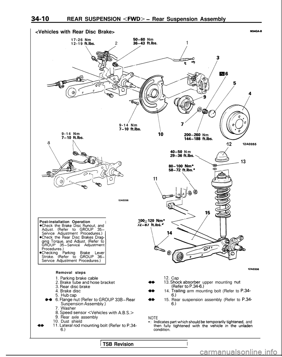
34-10REAR SUSPENSION
6
Nm
50-60Nm
12-1
9
ft.lbs.236-43 ft.lbs.1
9-14 N
m
7-10 ft.lbs.
200-240
Nm
144-188 ft.lbs.
9-14 Nm7-10 ft.lbs.
8
n
11
40-50 N
m
29-36 ft.lbs. \
1212AO355
1380-100 Nm*58-72 ft.lbs.*
\
Iloo-120 Nm*.-- -- _. . . ”Post-installation Operation*Check the Brake Disc Runout. andAdiust. (Refer to GROUP 35-
*Check the Rear Disc Brakes Draq-Iging Torque, and Adjust. (Refer foGROUP
35-ServiceAdjustmentISehice
Adjustment Procedures.) 1
Procedures.)@Checking Parking Brake LeverStroke. (Refer to GROUP 36-Service Adjustment Procedures.)
Removal steps
1. Parking
brake cable2.
Brake tube and hose bracket3. Rear
disc
brake4. Brake
disc5.
Hubcap~~6. Flange
nut
(Refer
to
GROUP 33B-Rear Suspension
Assembly.)
7.
Washer8. Speed sensor
WA0336
12. Cap13. Shock absorber
upper mounting nut
(Refer
to P.34-6.)14. Tr$ling arm mounting bolt (Refer to P.34-6.)15. Rear suspension assembly (Refer to P.34-6.)
c*
Y. Hear axle assembly10. Dust shield11. Lateral
rod mounting
bolt (Refer
to
P.34-6.)
NOTE*:indicates part which should be temporarily tightened, andthen fully tightened with
the vehicle in the unladencondition.
1 TSB RevisionI
Page 1096 of 1273
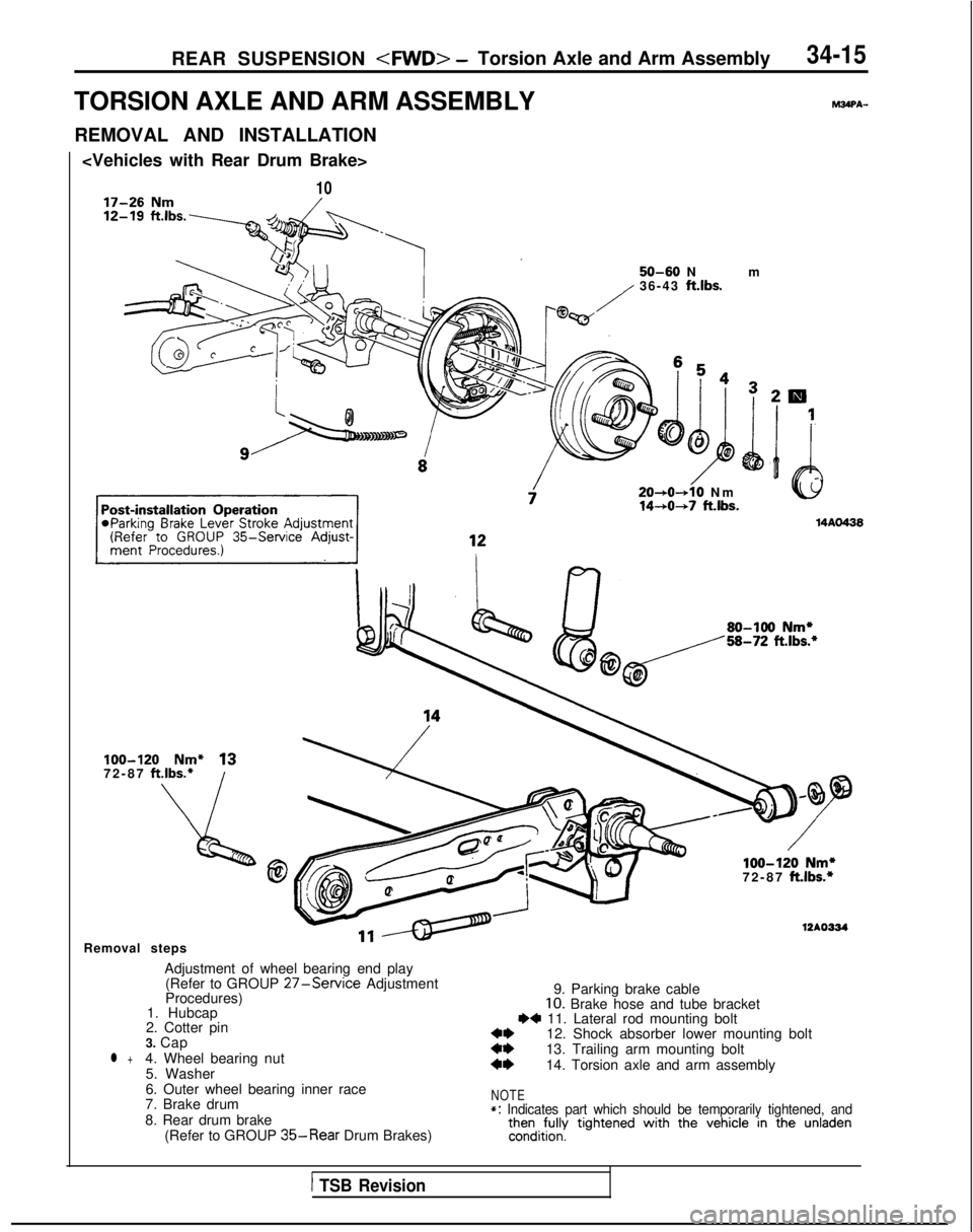
REAR SUSPENSION
TORSION AXLE AND ARM ASSEMBLYPAWPA-
REMOVAL AND INSTALLATION
10
50-60 N
m
36-43
ft.lbs.
20+0-+10 N
m
14-+0+7 ftlbs.
100-120 Nm* 1372-87 ft.lbs.*
loo-120 Nm*72-87 ft.lbs.*
Removal steps
Adjustment of wheel bearing end play
12AO334
(Refer to GROUP 27-Service Adjustment
Procedures) 9. Parking brake cable
1. Hubcap
10. Brake hose and tube bracket
2. Cotter pinI)+ 11. Lateral rod mounting bolt
3. Cap 12. Shock absorber lower mounting bolt
l +4. Wheel bearing nut::13. Trailing arm mounting bolt
5. Washer4*14. Torsion axle and arm assembly
6. Outer wheel bearing inner race
7. Brake drum
NOTE
8. Rear drum brake *: Indicates part which should be temporarily tightened, and
(Refer to GROUP 35-Rear Drum Brakes)then
fully
tightened with
the vehicle in the unladencondition.
1 TSB Revision
Page 1099 of 1273
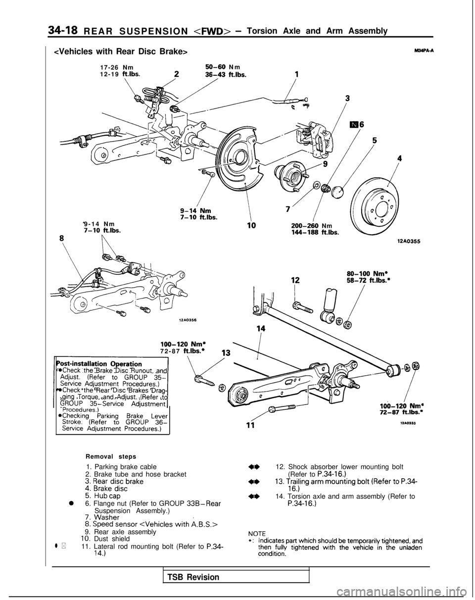
34-18 REAR SUSPENSION
WA-A
17-26 Nm
12-19 ftlbs.50-60 N
m
9-14 Nm
7-10 ft.lbs.200-2iO Nm144-189 ftlbs.
12A0355
loo-120 Nm*72-87 ft.lbs.*
*Check the Brake Disc Runout. and
*Check the Rear Disc Brakes Drag-ging Torque, and Adjust. (Refer to
Procedures.)*Checking Parking Brake LeverStroke. (Refer to GROUP 36-Service Adjustment Procedures.)
Removal steps
1. Parking brake cable
2. Brake tube and hose bracket
*I)12. Shock absorber lower mounting bolt
3. Rear disc
brake
(Refer to P.34-16.)
4. Brake disc4*13. Trailing
arm
mounting
bolt (Refer
to
P.34-
5. Hubcap16.)
l
6. Flange nut (Refer to GROUP 33B-Rear4*14. Torsion axle and arm assembly (Refer to
Suspension Assembly.)P.34-16.)
7. Washer
l *
8.
Speed sensor
11. Lateral rod mounting bolt (Refer to P.34-14.)
NOTE*:Indicates part which should be temporarily tightened, andthen fully tightened with the vehicle in the unladencondition.
TSB Revision
Page 1105 of 1273
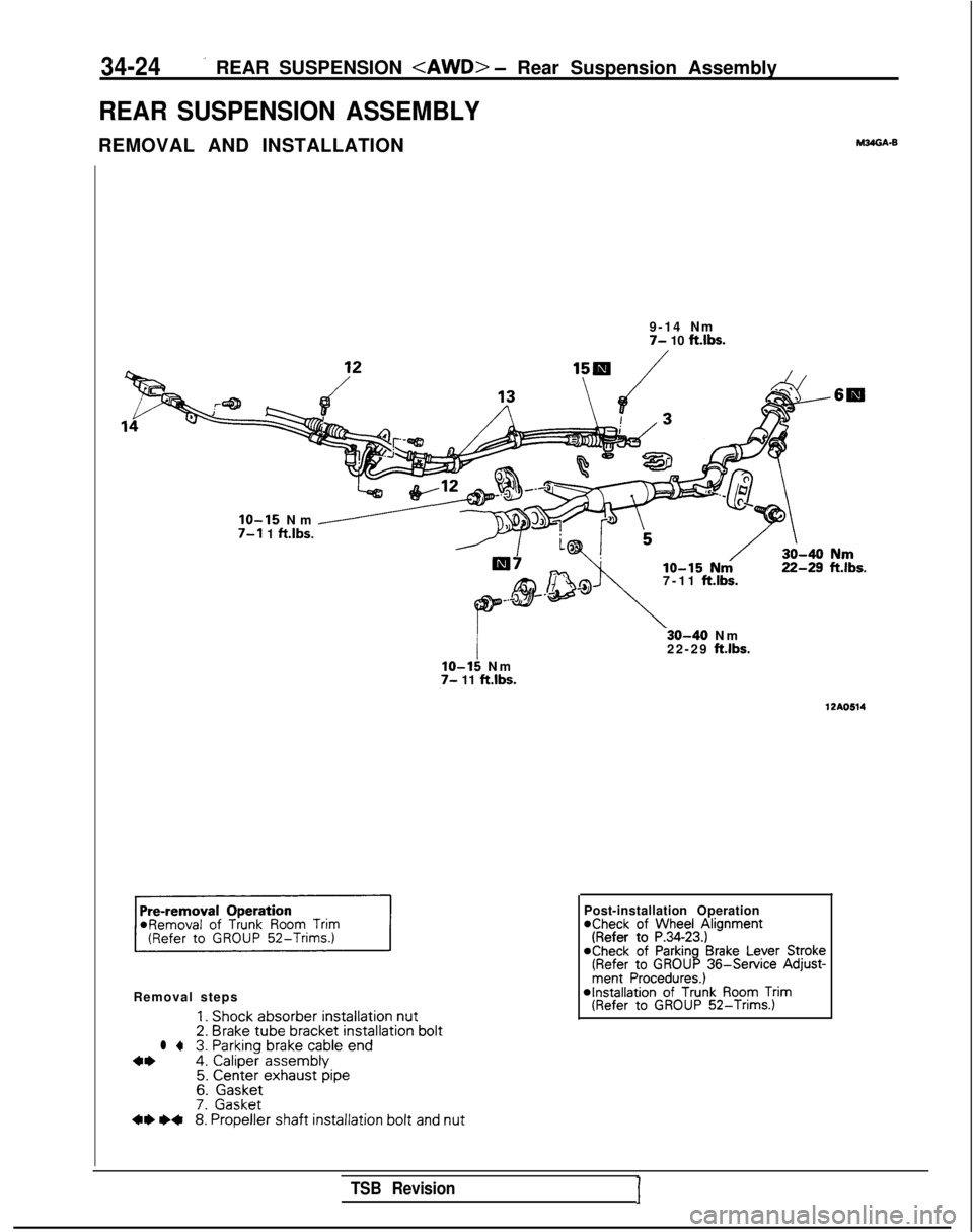
34-24’ REAR SUSPENSION
REAR SUSPENSION ASSEMBLY
REMOVAL AND INSTALLATIONM24GA.B
9-14 N
m
7- 10 ftlbs.
7-11
ft.lbs.
IO-15 Nm /7-l 1 ft.lbs.
Removal steps
1. Shock absorber
installation nut2.
Brake tube bracket
installation boltl +3. Parking
brake
cable
end4*4.
Caliper
assembly5. Center exhaust pipe6.
Gasket7.
Gasket** I)+8.
Propeller
shaft installation
bolt and nut
lo-15 N
m
7- 11 ft.lbs.
-30-40 N
m
22-29
ftlbs.
12AO514
Post-installation Operation*Check of Wheel Alignment(Refer to P.34-23.)aCheck of Parking Brake Lever Stroke(Refer to GROUP 36-Service
Adjust-ment Procedures.) *Installation
of Trunk Room Trim(Refer to GROUP 52-Trims.)
TSB RevisionI
Page 1106 of 1273

REAR SUSPENSION
40-50 Nm
29-36 ftlbs.
80-100 N
m
58-72
ft.lbs.
22-25 ftlbs.
\
50-60Nm36-4
3
ftlbs.
70-85Nm70-85Nm110-130 Nm51-61ft.lbs.51-61ftlbs.80-94 ftlbs.
12AO619
9. Self locking nut
10. Differential support member
II. Crossmember bracket
12. Parking brake cable and rear speed sensor
installation bolt
13. Cable band
14. Rear speed sensor connector
15. O-ring
16. Rear suspension assembly
TSB Revision1
Page 1107 of 1273
34-26REAR SUSPENSION
I 412AOlOS
J
TSB Revision
SERVICE POINTS OF REMOVAL
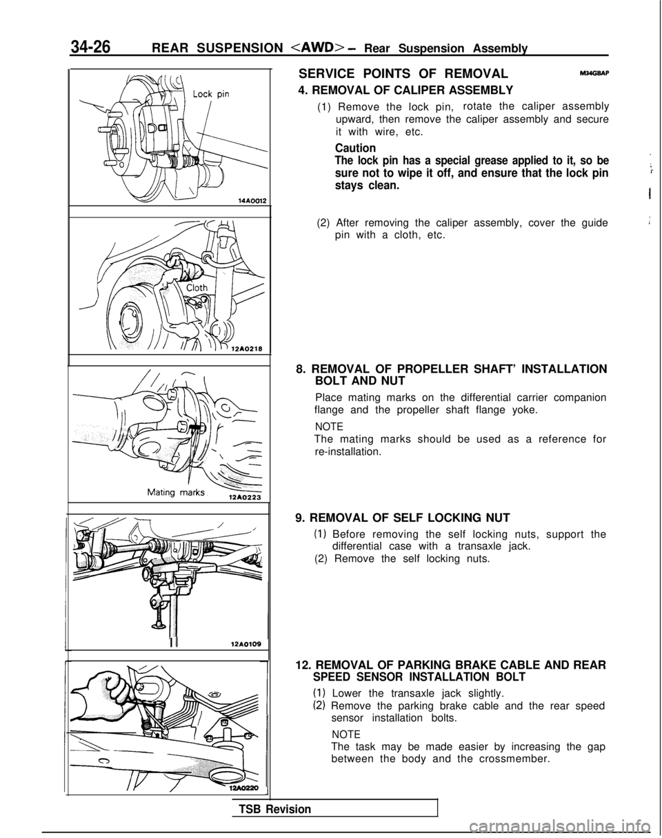
4. REMOVAL OF CALIPER ASSEMBLYM?dGSAP
(1) Remove the lock pin, rotate the caliper assembly
upward, then remove the caliper assembly and secure
it with wire, etc.
Caution
The lock pin has a special grease applied to it, so be
sure not to wipe it off, and ensure that the lock pin
stays clean.
I
(2) After removing the caliper assembly, cover the guide pin with a cloth, etc.
8. REMOVAL OF PROPELLER SHAFT’ INSTALLATION BOLT AND NUT
Place mating marks on the differential carrier companion
flange and the propeller shaft flange yoke.
NOTE
The mating marks should be used as a reference for
re-installation.
9. REMOVAL OF SELF LOCKING NUT
(1) Before removing the self locking nuts, support the differential case with a transaxle jack.
(2) Remove the self locking nuts.
12. REMOVAL OF PARKING BRAKE CABLE AND REAR
SPEED SENSOR INSTALLATION BOLT
(1) Lower the transaxle jack slightly.
(2) Remove the parking brake cable and the rear speed sensor installation bolts.
NOTE
The task may be made easier by increasing the gapbetween the body and the crossmember.