heater MITSUBISHI GALANT 1989 Service Repair Manual
[x] Cancel search | Manufacturer: MITSUBISHI, Model Year: 1989, Model line: GALANT, Model: MITSUBISHI GALANT 1989Pages: 1273, PDF Size: 37.62 MB
Page 38 of 1273
00-36
GENERAL -Recommended Lubricants and Lubricant Capacities Table
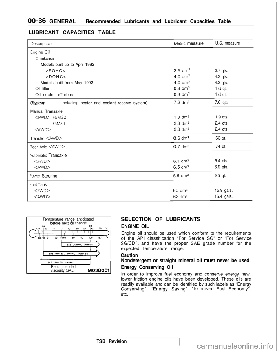
LUBRICANT CAPACITIES TABLE
Descrrptron
Engrne 011
Crankcase
Models built up to April 1992
Models built from May 1992
Oil filter
Oil cooler
(rncludrng heater and coolant reserve system)
Manual Transaxle
F5M3
1
Transfer
qear Axle
4utomatrc Transaxle
‘ower Steering %el
Tank
Metric measure
3.5 dm3
4.0 dm3
4.0 dm3
0.3 dm3
0.3 dm3
7.2 dm3
1.8 dm31.9 qts.
2.3
dm32.4 qts.
2.3 dm32.4 qts.
3.6 dm363 qt.
3.7
dm374 qt.
6.1 dm3
6.5 dms
3.9 dm3 60
dm3
62 dm3
U.S. measure
3.7qts.
4.2qts.
4.2qts.
1 I2qt.
1 I2qt.
7.6qts.
5.4 qts.
6.9 qts.
95 qt.
15.9 gals.
16.4 gals.
Temperature range anticipated before next oil chanae
SAE SW-30 SW-40IRecommendedviscosity (SAE) M03BOOl
SELECTION OF LUBRICANTS
ENGINE OIL
Engine oil should be used which conform to the requirements
of the API classification “For Service SG” or “For Service
SGKD”, and have the proper SAE grade number for the
expected temperature range.
Caution
Nondetergent or straight mineral oil must never be used.
Energy Conserving Oil
In order to improve fuel economy and conserve energy new,
lower friction engine oils have been developed. These oils are readily available and can be identified by such labels as “Energy
Conserving”, “Energy Saving”,
“Improved Fuel Economy”,
etc.
TSB Revision
Page 46 of 1273
GENERAL -Maintenance Service
(1O)Star-t engine and allow to idle for at least two minutes.
Then, with parking brake on, move selector
fever
momentarily to each position, ending in “N” Neutral
position.
(11)Add sufficient ATF to bring fluid level to lower mark.
Recheck fluid level after transaxle is at normal Operating
temperature. Fluid level should be between upper and lower marks of
“HOT” range, Insert dipstick fully to prevent dirt from
entering transaxle.
OOA0051
11 .ENGINE
COOLANT (Change)MOOSEEAC
Check the cooling system parts, such as radiator, heater,
and oil cooler hoses, thermostat and connections for
leakage and damage.
CHANGE COOLANT
1. Remove the radiator cap.
2. Loosen the drain plug to drain the coolant.
3. Drain the coolant from the reserve tank.
4. After draining the coolant, tighten the drain plug securely.
5.Supply the coolant into the radiator until it is filled up to
its filler neck.
6. Supply the coolant into the reserve tank.
7. After warming the engine until the thermostat opens, remove the radiator cap and check the coolant level.
8.Supply the coolant into the radiator until it is filled up to
its filler neck, and install the radiator cap securely.
9.Fill the reserve tank with coolant up to the “FULL” line.
14K512
1 12.DISC BRAKE PADS (Inspect for wear) MWSBFA
Check for fluid contamination and wear. Replace complete
set of pads if defective.
Caution
The pads for the right and left wheels should be
reDlaced at the same time. Never “split” or intermix
brkke pad sets.
All four pads must be replace as a complete set.
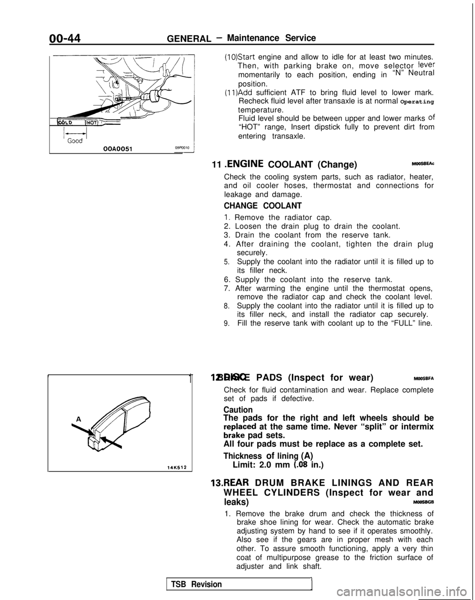
Thickness of lining (A)
Limit: 2.0 mm (.08 in.)
13.REAR DRUM BRAKE LININGS AND REAR
WHEEL CYLINDERS (Inspect for wear and
leaks)MOOSBGB
1. Remove the brake drum and check the thickness of brake shoe lining for wear. Check the automatic brake
adjusting system by hand to see if it operates smoothly.
Also see if the gears are in proper mesh with each
other. To assure smooth functioning, apply a very thin
coat of multipurpose grease to the friction surface of
adjuster and link shaft.
TSB Revision1
Page 65 of 1273
ENGINE
35-4
5
25-33 35-45 Nm
25-33
ft.lbs.
24
35-45 N
m
25-33
ft.lbs.
23-2
7
250166309
I23
:l;nbs.
50-65 Nm
36-47 ft.lbs.
dv--iu wm: ’22-29 ft.lbs. \ d.(,(I3L i‘9
50-65 Nm*Cb36-47 ft.lbs.* -
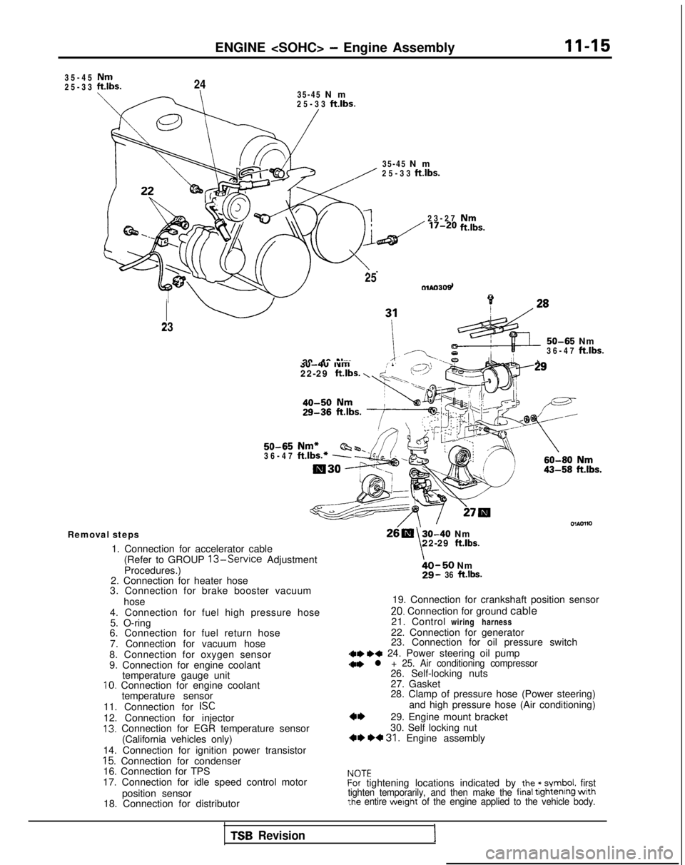
Removal steps
1. Connection for accelerator cable(Refer to GROUP
13-Service Adjustment
Procedures.)
2. Connection for heater hose
3. Connection for brake booster vacuum
hose
4. Connection for fuel high pressure hose 5. O-ring
6. Connection for fuel return hose
7. Connection for vacuum hose
8. Connection for oxygen sensor
9. Connection for engine coolant temperature gauge unit
10. Connection for engine coolant
temperature sensor
11. Connection for
ISC12. Connection for injector13. Connection for EGR temperature sensor (California vehicles only)
14. Connection for ignition power transistor
15. Connection for condenser
16. Connection for TPS
17. Connection for idle speed control motor
position sensor
18. Connection for distributor
30-40 Nm
\22-29 ft.lbs.
bO-50 Nm29- 36 ft.lbs.
19. Connection for crankshaft position sensor
20. Connection for ground cable
21. Control wiring harness
22. Connection for generator
23. Connection for oil pressure switch
dae I)* 24. Power steering oil pump
28. Clamp of pressure hose (Power steering) and high pressure hose (Air conditioning)
29. Engine mount bracket
30. Self locking nut
,** *+ 31. Engine assembly
IdOTEf-or tightening locations indicated by the * symbol. firsttighten temporarily, and then make the final tightenrng wrth?he entire werght of the engine applied to the vehicle body.
TSB Revision1
Page 67 of 1273
ENGINE
ENGINE ASSEMBLY
REMOVAL AND INSTALLATION
II-17
Pre-removal Operation@Eliminating Fuel Pressure in Fuel Line (Refer to GROUP 13-Service Adjustment Proce-
dures.)
l Removal of the Hood
(Refer to GROUP
42-Hood.)l Draining of the Engine Coolant
(Refer to GROUP 00-Maintenance Service)
l Removal of the Transaxle (Refer to GROUP
22,23-Transaxle.)l Removal of the Radiator(Refer to GROUP 14-Radiator.)
Fuel rail
603AOO70
Engine oil
Post-installation Operationl Installation of the Radiator (Refer to GROUP 14-Radiator.)l Installation of the Transaxle(Refer to GROUP 22, 23-Transaxle.)l Refilling of the Engine Coolant
(Refer to GROUP 00-Maintenance Service.)
l Installation of the Hood (Refer to GROUP
42-Hood.)
4-6 Nm3-F ft.lbs.
I6m
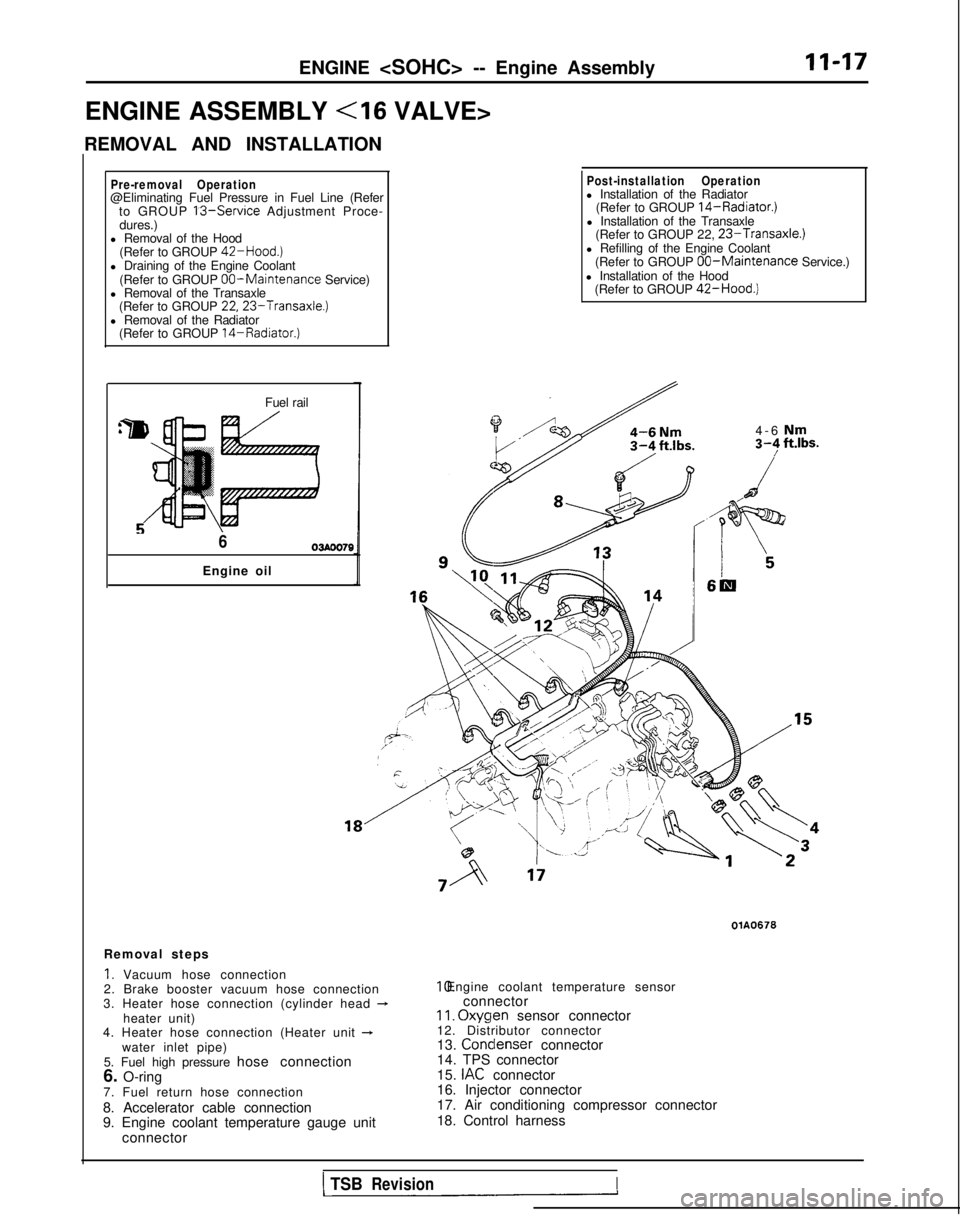
Removal steps
1. Vacuum hose connection
2. Brake booster vacuum hose connection
3. Heater hose connection (cylinder head
-heater unit)
4. Heater hose connection (Heater unit +water inlet pipe)
5. Fuel high pressure hose connection
6. O-ring
7. Fuel return hose connection
8. Accelerator cable connection
9. Engine coolant temperature gauge unit connector
OlA0676 10. Engine coolant temperature sensor
connector
II. Oxyqen
sensor connector
12. Distributor connector
13. Condenser
connector
14. TPS connector
15.
IAC connector
16. Injector connector
17. Air conditioning compressor connector
18. Control harness
1 TSBRevisionI
Page 76 of 1273
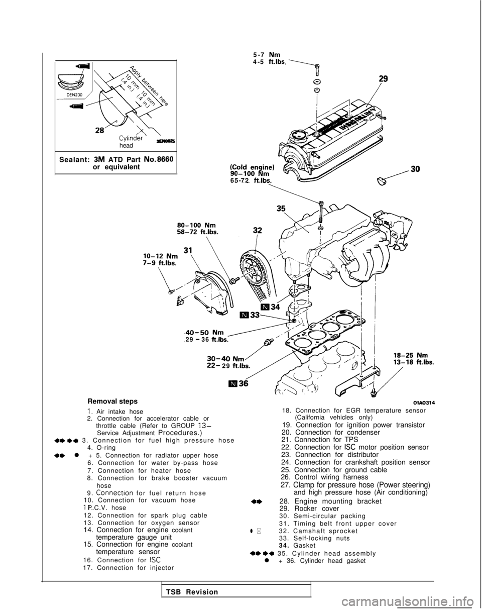
Cyl1n&r’ ;;(oozhead
Sealant: 3M
ATD Part No.8660
or equivalent 5-7
Nm4-5 ft.lbs 90-100
Nm65-72 ftlbs.
40-50 Nm /29 - 36 ft.lbs.
30-40 Nm22- 29
ftlbs.
Removal steps
I. Air intake hose
2. Connection for accelerator cable or
throttle cable (Refer to GROUP
13-Service Adjustment Procedures.)+e +a 3. Connection for fuel high pressure hos
e
4. O-ring
+e l + 5. Connection for radiator upper hose
6. Connection for water by-pass hose
7. Connection for heater hose
8. Connection for brake booster vacuum
hose
9.
Connectron for fuel return hos
e
10. Connection for vacuum hose 11. P.C.V. hose
12. Connection for spark plug cable
13. Connection for oxygen sensor
14. Connection for engine coolant temperature gauge unit
15. Connection for engine coolant
temperature sensor
16. Connection for
ISC17. Connection for injector
olAo314
l *
18. Connection for EGR temperature sensor (California vehicles only)
19. Connection for ignition power transistor
20. Connection for condenser
21. Connection for TPS
22. Connection for
ISC motor position sensor
23. Connection for distributor
24. Connection for crankshaft position sensor
25. Connection for ground cable
26. Control wiring harness
27. Clamp for pressure hose (Power steering)and high pressure hose (Air conditioning)
28. Engine mounting bracket
29. Rocker cover
30. Semi-circular packing
31. Timing belt front upper cover
32. Camshaft sprocket 33. Self-locking nuts
34. Gasket
+e ++ 35. Cylinder head assembl
y
l + 36. Cylinder head gasket
TSB Revision
Page 80 of 1273
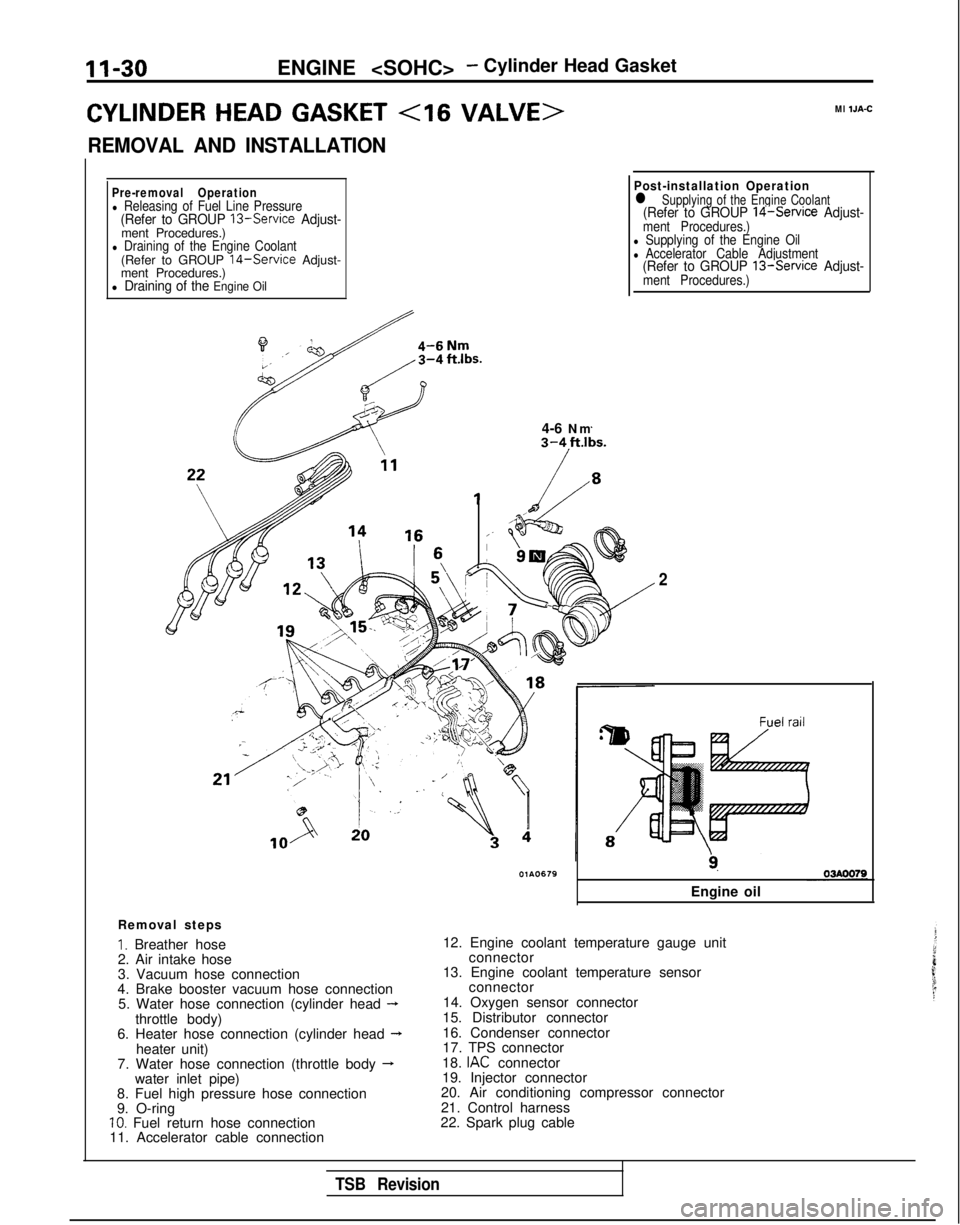
II-30ENGINE
CYLINDER HEAD GASKET
REMOVAL AND INSTALLATION
Ml IJA-C
Pre-removal Operationl Releasing of Fuel Line Pressure(Refer to GROUP 13-Service Adjust-ment Procedures.)l Draining of the Engine Coolant(Refer to GROUP 14-Service Adjust-
ment Procedures.)
l Draining of the Engine Oil
il4-6 Nm
Post-installation Operationl Supplying of the Engine Coolant(Refer to GROUP 14-Service Adjust-ment Procedures.)l Supplying of the Engine Oill Accelerator Cable Adjustment(Refer to GROUP 13-Service Adjust-ment Procedures.)
Removal steps
I. Breather hose
2. Air intake hose
3. Vacuum hose connection
4. Brake booster vacuum hose connection 5. Water hose connection (cylinder head
-throttle body)
6. Heater hose connection (cylinder head --Lheater unit)
7. Water hose connection (throttle body -water inlet pipe)
8. Fuel high pressure hose connection
9. O-ring
10. Fuel return hose connection
11. Accelerator cable connection
2
9.
Engine oil
12. Engine coolant temperature gauge unit connector
13. Engine coolant temperature sensor connector
14. Oxygen sensor connector
15. Distributor connector
16. Condenser connector
17. TPS connector
18.
IAC connector
19. Injector connector
20. Air conditioning compressor connector
21. Control harness
22. Spark plug cable
TSB Revision
Page 113 of 1273
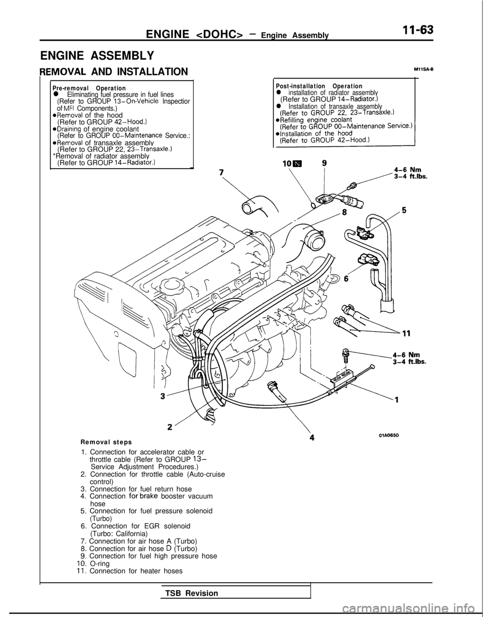
ENGINE
ENGINE ASSEMBLY
IEMOVAL AND INSTALLATION
Pre-removal Operationl Eliminating fuel pressure in fuel lines
(Refer to GROUP 13-On-Vehicle lnspectior
of MFI Components.)*Removal of the hood
(Refer to GROUP 42-Hood.)
eDraining of engine coolant(Refer to GROUP 00-Maintenance
Service.:@Removal of transaxle assembly
(Refer to GROUP 22, 23-Transaxle.)*Removal of radiator assembly
(Refer to GROUP 14-Radiator.)
MIISA-6
Post-installation Operationl installation of radiator assembly(Refer to GROUP 14-Radiator.)l Installation of transaxle assembly
Removal steps
1. Connection for accelerator cable or throttle cable (Refer to GROUP
13-Service Adjustment Procedures.)
2. Connection for throttle cable (Auto-cruise control)
3. Connection for fuel return hose
4. Connection
forbrake booster vacuum
hose
5. Connection for fuel pressure solenoid(Turbo)6. Connection for EGR solenoid (Turbo: California)
7. Connection for air hose A (Turbo) 8. Connection for air hose
D (Turbo)9. Connection for fuel high pressure hose10. O-ring11. Connection for heater hoses
TSB Revision
Page 123 of 1273
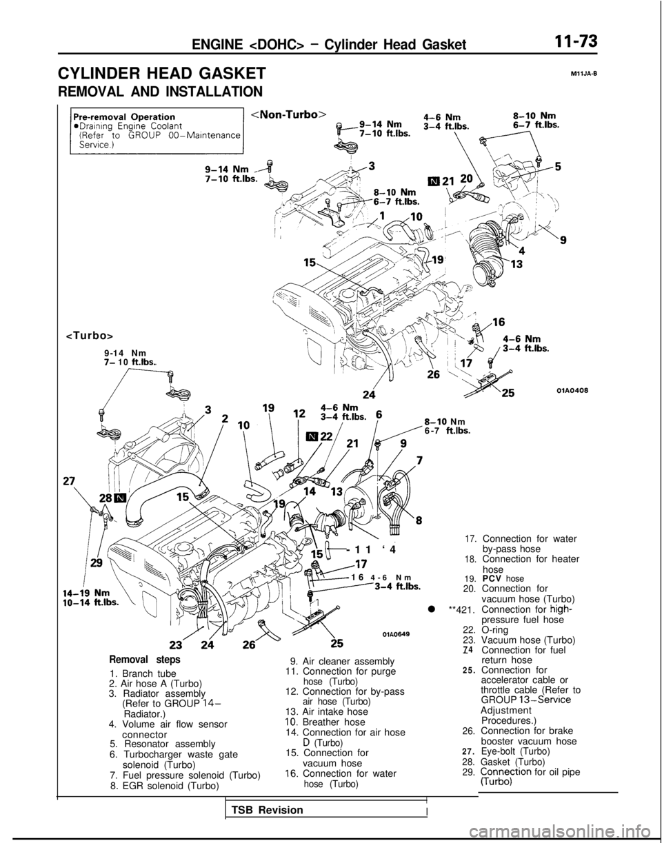
ENGINE
CYLINDER HEAD GASKET
MllJA-9
REMOVAL AND INSTALLATION
7- 10 ft.lbs.
OlA0408
8-10 Nm
6-7 ft.lbs.
-11 ‘
4
A17
-16
4-6 N
m
---3-4
ftlbs.
OlA0649
17.
18.
19.20.
l **421.
22.
23.
74Removal steps
1. Branch tube
2. Air hose A (Turbo)
3. Radiator assembly (Refer to GROUP
14-Radiator.)
4. Volume air flow sensor
connector
5. Resonator assembly
6. Turbocharger waste gate solenoid (Turbo)
7. Fuel pressure solenoid (Turbo) 8. EGR solenoid (Turbo)
-
9. Air cleaner assembly
11. Connection for purge25.
hose (Turbo)12. Connection for by-passair hose (Turbo)13. Air intake hose10. Breather hose
14. Connection for air hose26.
D (Turbo)15. Connection for27.
vacuum hose28.
16. Connection for water29.
hose (Turbo)
I
Connection for water
by-pass hose
Connection for heater
hose
PCV hose
Connection for
vacuum hose (Turbo)
Connection for
high-pressure fuel hose
O-ring
Vacuum hose (Turbo) Connection for fuel
return hose
Connection for
accelerator cable or
throttle cable (Refer to GROUP
13-ServiceAdjustment
Procedures.)
Connection for brake
booster vacuum hose
Eye-bolt (Turbo)
Gasket (Turbo)
pun;;;tron for oil pipe
TSB Revision
I
Page 432 of 1273
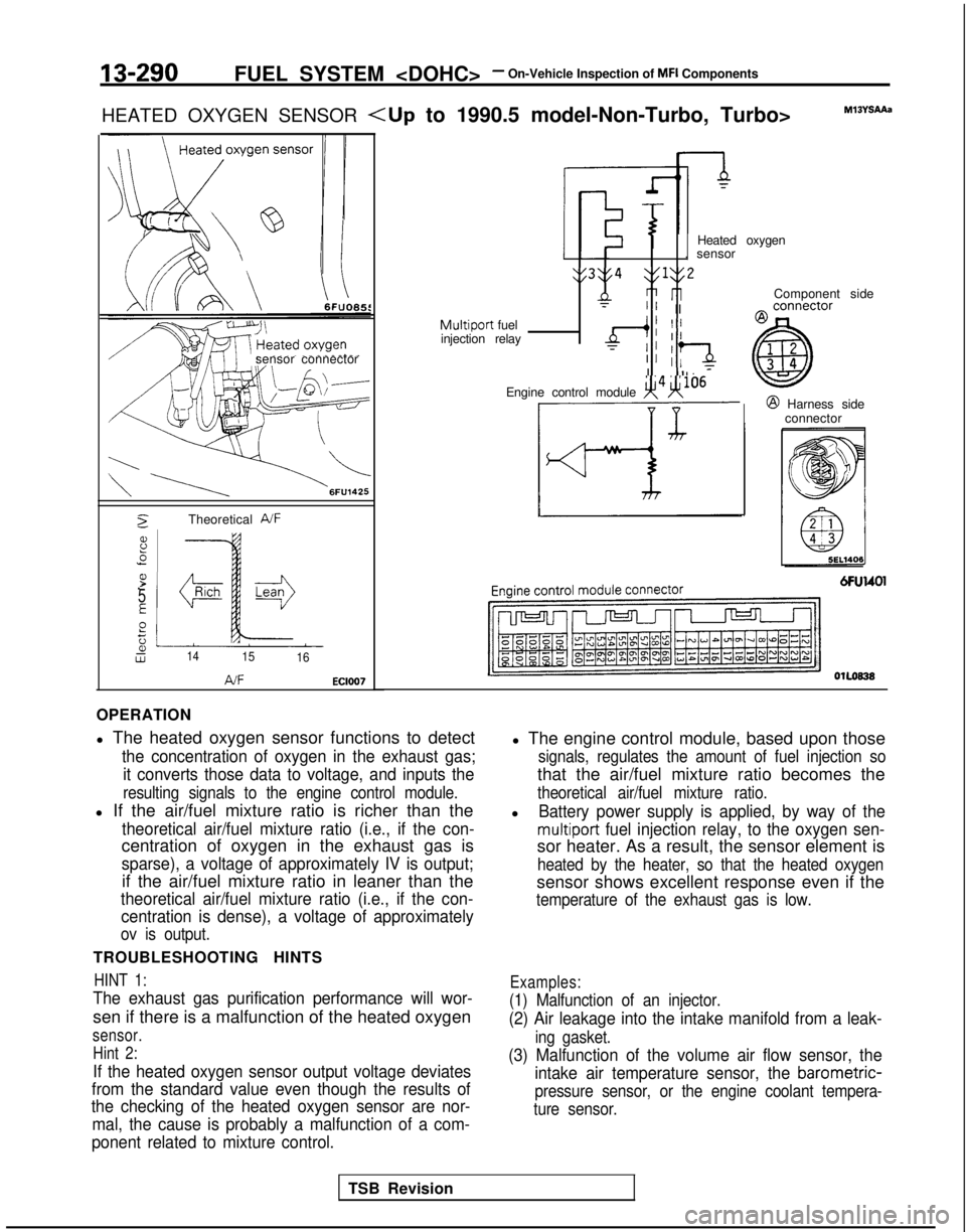
13-290FUEL SYSTEM
HEATED OXYGEN SENSOR
sensor connector
2Theoretical A/F
8.5
P.-
5
E
Pt;2Lw1415 16
AJFEC1007
Component side
Heated oxygen
. sensor
y3y4 $1y2
nri rlT” IIMultiport fuel
injection relayd; II
TII :‘aII Il. 7
Engine control module x4H106@ Harness side
connector
OlLoB38
OPERATION
l The heated oxygen sensor functions to detect
the concentration of oxygen in the exhaust gas;
it converts those data to voltage, and inputs the
resulting signals to the engine control module.
l If the air/fuel mixture ratio is richer than the
theoretical air/fuel mixture ratio (i.e., if the con-
centration of oxygen in the exhaust gas is
sparse), a voltage of approximately IV is output;
if the air/fuel mixture ratio in leaner than the
theoretical air/fuel mixture ratio (i.e., if the con-centration is dense), a voltage of approximately
ov is output.
TROUBLESHOOTING HINTS
HINT 1:
The exhaust gas purification performance will wor-
sen if there is a malfunction of the heated oxygen
sensor.
Hint 2:
If the heated oxygen sensor output voltage deviates
from the standard value even though the results of
the checking of the heated oxygen sensor are nor-
mal, the cause is probably a malfunction of a com-
ponent related to mixture control.
l The engine control module, based upon those
signals, regulates the amount of fuel injection so
that the air/fuel mixture ratio becomes the
theoretical air/fuel mixture ratio.
lBattery power supply is applied, by way of the
multiport fuel injection relay, to the oxygen sen-
sor heater. As a result, the sensor element is
heated by the heater, so that the heated oxygen
sensor shows excellent response even if the
temperature of the exhaust gas is low.
Examples:
(1) Malfunction of an injector.
(2) Air leakage into the intake manifold from a leak-
ing gasket.
(3) Malfunction of the volume air flow sensor, the intake air temperature sensor, the
barometric-
pressure sensor, or the engine coolant tempera-
ture sensor.
TSB Revision
Page 509 of 1273
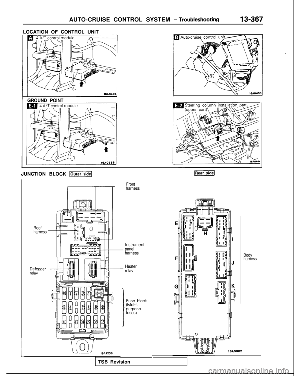
AUTO-CRUISE CONTROL SYSTEM - Troubleshootinn13-367
LOCATION OF CONTROL UNIT
w
16AO406
GROUND POINT
JUNCTION BLOCK p-;a
Front
harness
t
Instrument
Roof
harnessr’ II
Ji
-I
$!&;Ipanel
harness Body
harness
z$gger ~----#$jfiillITiHeater- relav
7
J
fuses)
16A0002m36I
TSB Revision