set MITSUBISHI GALANT 1989 Service User Guide
[x] Cancel search | Manufacturer: MITSUBISHI, Model Year: 1989, Model line: GALANT, Model: MITSUBISHI GALANT 1989Pages: 1273, PDF Size: 37.62 MB
Page 61 of 1273
ENGINE
Access
cover
,-
(0 a0
<
0 0
0 0
0
101 II0221
Access cover
Screwdriver slot
3EN075
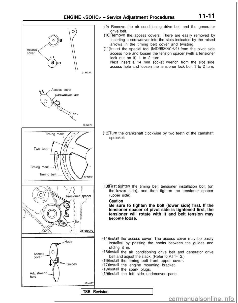
(9) Remove the air conditioning drive belt and the generator drive belt.
(10)Removle the access covers. There are easily removed by
inserting a screwdriver into the slots indicated by the raised
arrows in the timing belt cover and twisting. (1l)lnset-t
the special tool (MD998051-01)
from the pivot side
access hole and loosen the tension spacer (with a tensioner lock nut on it) 1 to 2 turn.
Next insert a 14 mm socket wrench from the slot side
access hole and loosen the tensioner lock bolt 1 to 2 turn.
(12)Turn the crankshaft clockwise by two teeth of the camshaft
sprocket.
(13)First ticjhten the timing belt tensioner installation bolt (on
the
lo&er side), and then tighten the tensioner spacer
(upper side).
Caution
Be sure to tighten the bolt (lower side) first. lf the
tensioner spacer of pivot side is tightened first, the
tensioner will rotate with it and belt tension may
becorn; loose.
(14)lnstall the access cover. The access cover may be easily
installeNd by passing the hooks between the guides and
sliding it in.
(15)lnstall the air conditioning drive belt and generator drive
belt and adjust the slack. (Refer to P.l
l-l 2.)
(16)lnstall the timing belt front upper cover.
(17)lnstall the engine mounting bracket.
(18)lnstall the spark plugs.
(19)lnstall the left side undercover panel.
TSB Revision
Page 62 of 1273
 Check that the belts are not damaged.
Power steenng
oil pump
pulley
\
W
ater
pump
pulley
I Tension
pulle")
11-12ENGINE
DRIVE BELTS TENSION ADJUSTMENT
MllFMBBO
(1) Check that the belts are not damaged.
Power steenng
oil pump
pulley
\
W
ater
pump
pulley
I Tension
pulley/
Generator
compressor
Crankshaft
pulley pulley
We
Spindle----As.
IRESET button (2) Apply
IOON (22 Ibs.) force to the belt back midwa
y
between the pulleys as shown in the figure, measure the
deflection or, by using a belt-tension gauge, check the
belt’s tension.
Standard value:
Gauge250-500500-700400 (88)
N (Ibs.)(55-110)(110-154)
ForAKDeflection Approx. 8.05.0-5.56.0-7.0
compressor mm (in.)(.315)(.197-,217) (.236-.276)
For P/S
pump Gauge
250-500320-400470-570
N (Ibs.)(55-110)(71-88)(104-126)
Deflection 6.0-9.0
-mm (in.)(.236-,354)
NOTE
There is more than one type of belt-tension gauge (type A and
type
8, for example), so be sure to use the gauge according to
its instructions for use.
1 TSB Revision
Page 99 of 1273
ENGINE
Crankshaft
sprocket “B”
/
Crankshaft/\ \sprocket Flange Crankshaft 6~~~72
Plain washer-J
26
@
Plug
6EN0281
I
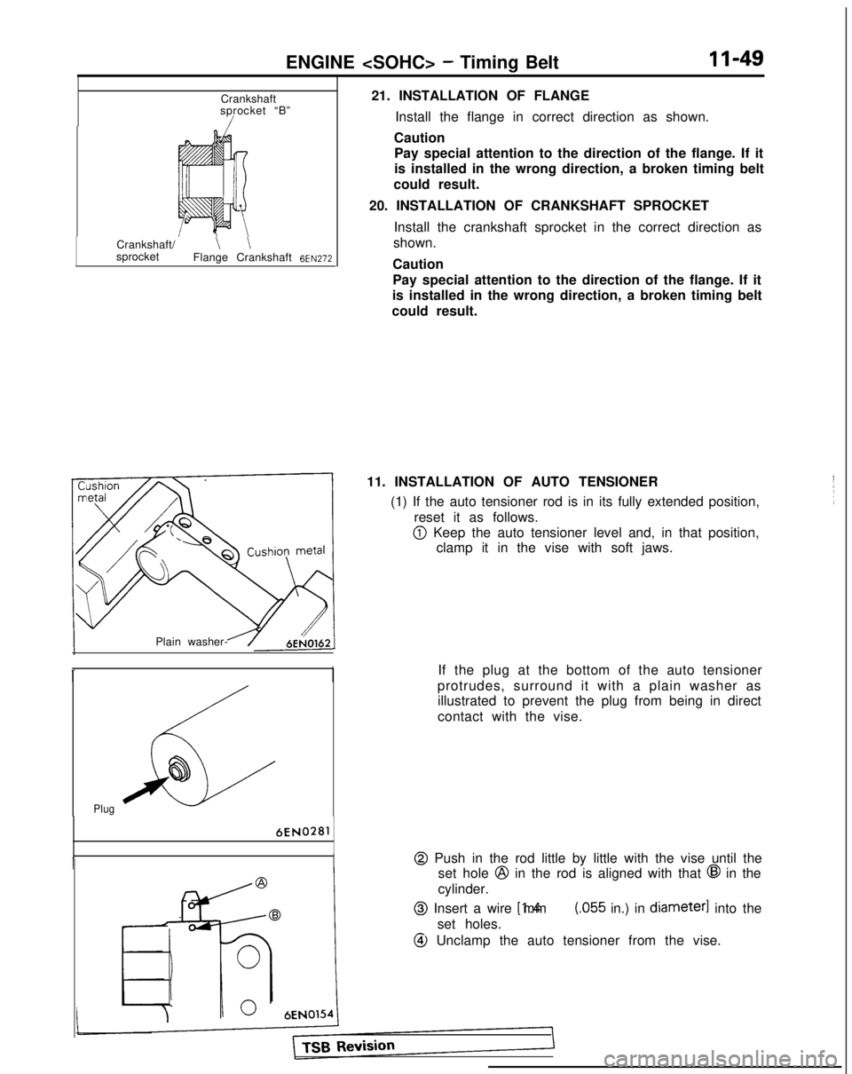
21. INSTALLATION OF FLANGE
Install the flange in correct direction as shown.
Caution Pay special attention to the direction of the flange. If it
is installed in the wrong direction, a broken timing belt
could result.
20. INSTALLATION OF CRANKSHAFT SPROCKET Install the crankshaft sprocket in the correct direction as
shown.
Caution
Pay special attention to the direction of the flange. If it
is installed in the wrong direction, a broken timing belt
could result.
11. INSTALLATION OF AUTO TENSIONER (1) If the auto tensioner rod is in its fully extended position,reset it as follows.
@ Keep the auto tensioner level and, in that position,clamp it in the vise with soft jaws.
If the plug at the bottom of the auto tensioner
protrudes, surround it with a plain washer as illustrated to prevent the plug from being in direct
contact with the vise.
@ Push in the rod little by little with the vise until the set hole
@ in the rod is aligned with that @ in the
cylinder.
@ Insert a wire [1.4 mm (055 in.) in diameter]
into the
set holes.
@ Unclamp the auto tensioner from the vise.
Page 101 of 1273
ENGINE
r
L Camshaft sprocket
Idler
pulley
/Oil pumpOlA0668
sprocket
6EN0175
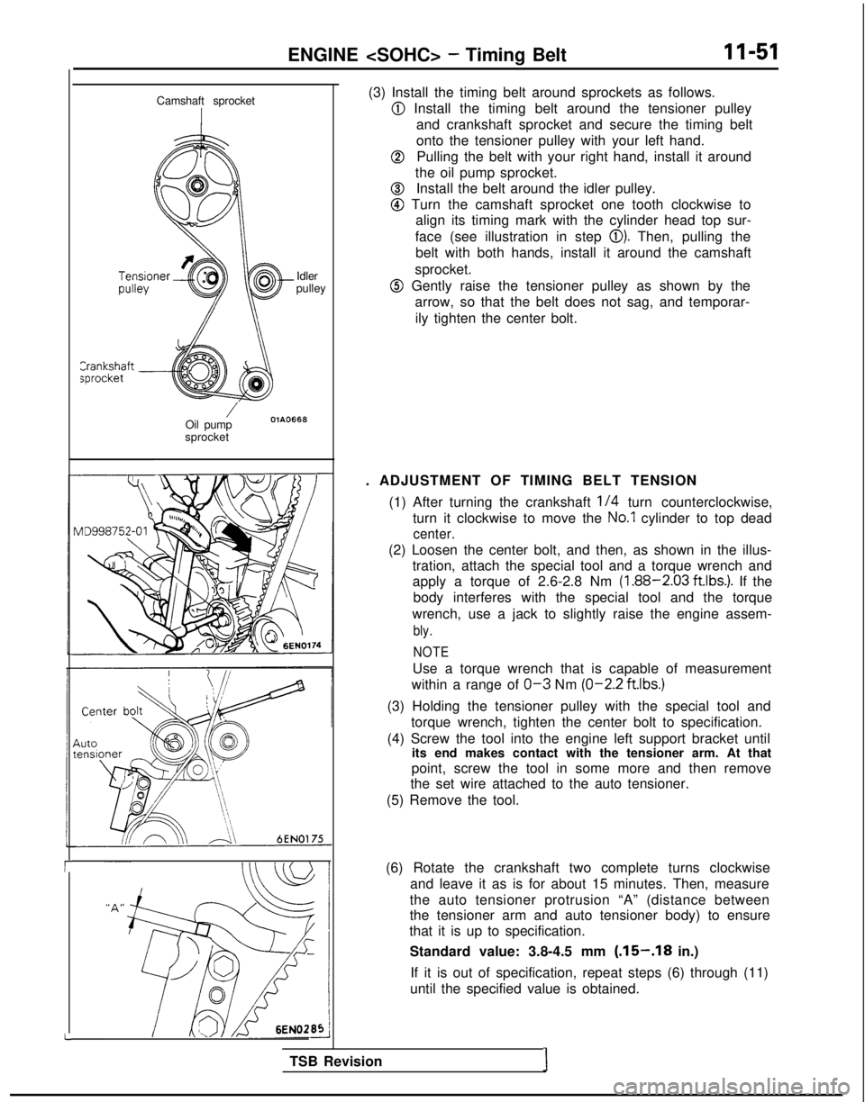
(3) Install the timing belt around sprockets as follows.
@ Install the timing belt around the tensioner pulley
and crankshaft sprocket and secure the timing belt
onto the tensioner pulley with your left hand.
@Pulling the belt with your right hand, install it around
the oil pump sprocket.
@Install the belt around the idler pulley.
@ Turn the camshaft sprocket one tooth clockwise to align its timing mark with the cylinder head top sur-
face (see illustration in step
0). Then, pulling the
belt with both hands, install it around the camshaft
sprocket.
@ Gently raise the tensioner pulley as shown by the arrow, so that the belt does not sag, and temporar-
ily tighten the center bolt.
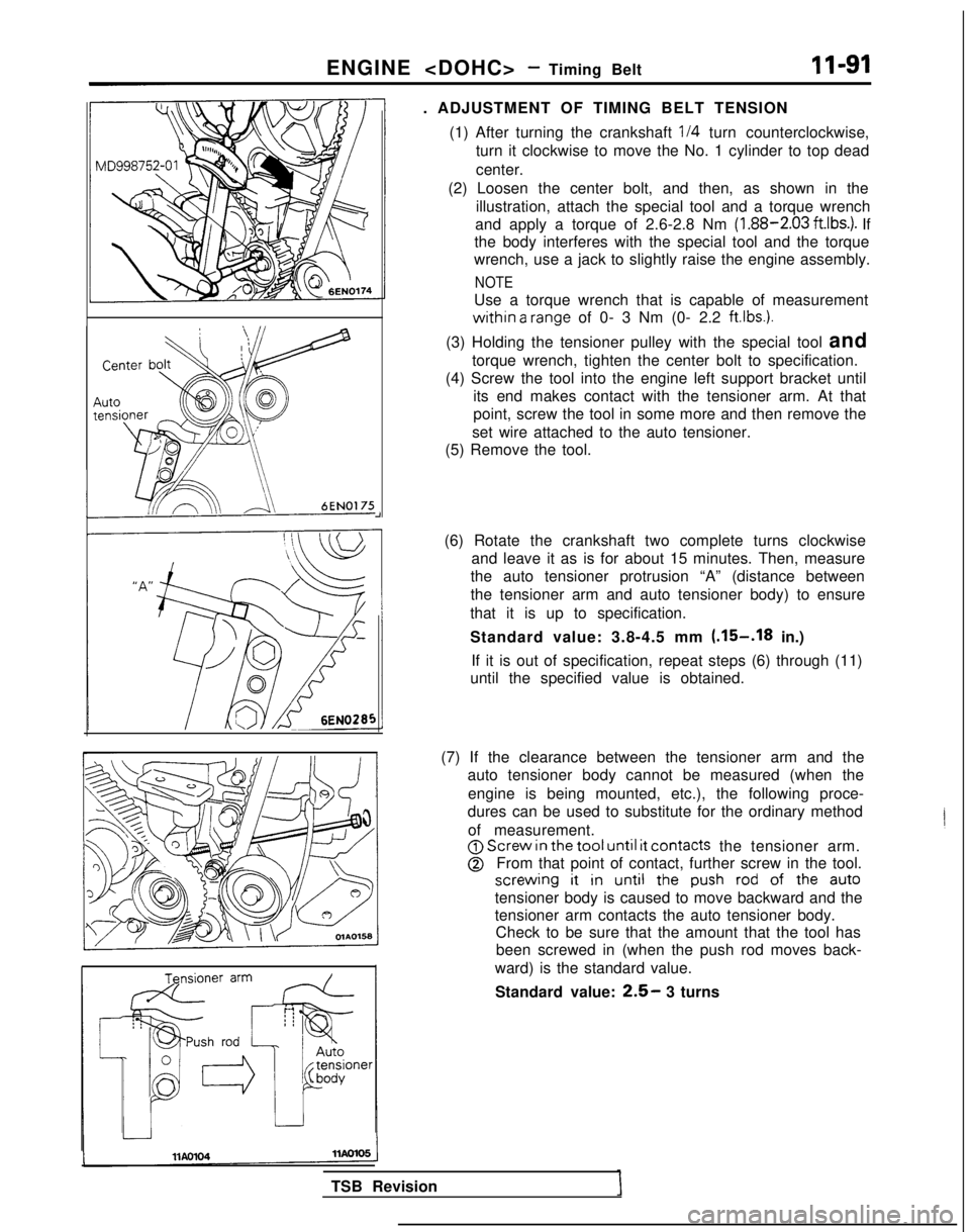
. ADJUSTMENT OF TIMING BELT TENSION (1) After turning the crankshaft
l/4 turn counterclockwise,
turn it clockwise to move the
No.1 cylinder to top dead
center.
(2) Loosen the center bolt, and then, as shown in the illus- tration, attach the special tool and a torque wrench and
apply a torque of 2.6-2.8 Nm
(1.88-2.03 ft.lbs.). If the
body interferes with the special tool and the torque
wrench, use a jack to slightly raise the engine assem-
bly.
NOTE
Use a torque wrench that is capable of measurement
within a range of
O-3 Nm (O-2.2
ftlbs.)
(3) Holding the tensioner pulley with the special tool and
torque wrench, tighten the center bolt to specification.
(4) Screw the tool into the engine left support bracket until its end makes contact with the tensioner arm. At that
point, screw the tool in some more and then remove
the set wire attached to the auto tensioner.
(5) Remove the tool.
(6) Rotate the crankshaft two complete turns clockwise and leave it as is for about 15 minutes. Then, measure
the auto tensioner protrusion “A” (distance between
the tensioner arm and auto tensioner body) to ensure
that it is up to specification.
Standard value: 3.8-4.5 mm
(.15-.18 in.)
If it is out of specification, repeat steps (6) through (11)
until the specified value is obtained.
TSB Revision
I
Page 108 of 1273
11-58ENGINE
4 Timing belt sideI
6EN0515
(3) lf
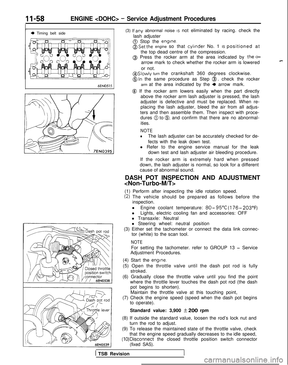
any abnormal noise IS not eliminated by racing. check the
lash adjuster
@ Stop the engine.
@ Set the engine so that cylinder
No. 1 IS positioned at
the top dead centre of the compression.
@ Press the rocker arm at the area indicated by the+
arrow mark to check whether the rocker arm is lowered
or not.
@ Slowly turn the crankshaft 360 degrees clockwise.
@ ln the same procedure as Step 0, check the rocker
arm at the area indicated by the
4 arrow mark.
@ If the rocker arm lowers easily when the part directly above the rocker arm lash adjuster is pressed, the lash
adjuster is defective and must be replaced. When re- placing the lash adjuster, bleed the air from all adjus-
ters and then assemble them. Then inspect with proce- dures
@I to 0, and confirm that there are no abnormal-
ities.
NOTE
lThe lash adjuster can be accurately checked for de-
fects with the leak down test.
l Refer to the engine service manual for the leak
down test and lash adjuster air bleeding procedure.
If the rocker arm is extremely hard when pressed
down, the lash adjuster is normal, so look for a different
cause of abnormal sound.
DASH POT INSPECTION AND ADJUSTMENT
(1) Perform after inspecting the idle rotation speed.
(2) The vehicle should be prepared as follows before the inspection.
l Engine coolant temperature:
80- 95°C
(176- 203°F)
lLights, electric cooling fan and accessories: OFF
l Transaxle: Neutral
l Steering wheel: neutral position
(3) Either set the tachometer or connect the data link connec- tor (white) to the scan tool.
NOTE
For setting the tachometer. refer to GROUP 13 - Service
Adjustment Procedures.
(4) Start the
engine.
(5) Open the throttle valve until the dash pot rod is fully
stroked.
(6) Gradually close the throttle valve until you find the point where the throttle lever touches the dash pot rod (the dashpot begins to shorten).
Maintain the throttle valve at this touching point,
(7) Check the engine speed (speed when the dash pot begins to operate).
Standard value: 3,900
f 200 rpm
(8) If outside the standard value, loosen the rod’s lock nut and turn the rod to adjust.
(9) To release the maintained state of the throttle valve, check that the engine speed gradually decreases to the idle speed, (10)Disconnect
the closed throttle position switch connector
(fixed SAS).
1 TSB Revision
Page 109 of 1273
ENGINE
7 Go;;ikv position
switch
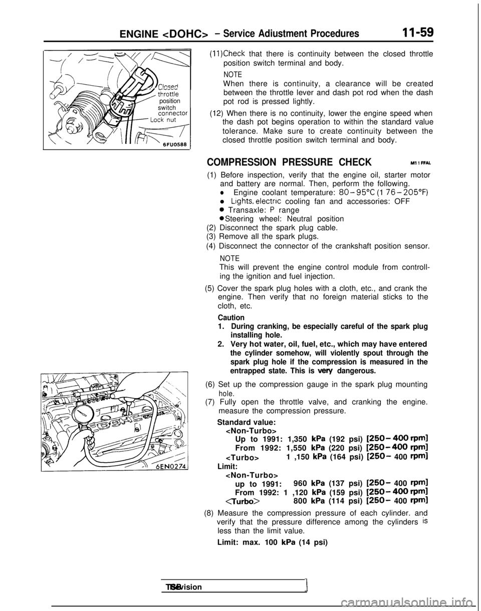
(11)Check that there is continuity between the closed throttle
position switch terminal and body.
NOTE
When there is continuity, a clearance will be created between the throttle lever and dash pot rod when the dash
pot rod is pressed lightly.
(12) When there is no continuity, lower the engine speed when the dash pot begins operation to within the standard value
tolerance. Make sure to create continuity between the
closed throttle position switch terminal and body.
COMPRESSION PRESSURE CHECK Ml 1 FFAL
(1) Before inspection, verify that the engine oil, starter motor
and battery are normal. Then, perform the following.
lEngine coolant temperature: 80- 95°C
(1 76- 205’F)
l Lights, electnc
cooling fan and accessories: OFF
0 Transaxle: P range 0 Steering wheel: Neutral position
(2) Disconnect the spark plug cable.
(3) Remove all the spark plugs.
(4) Disconnect the connector of the crankshaft position sensor.
NOTE
This will prevent the engine control module from controll- ing the ignition and fuel injection.
(5) Cover the spark plug holes with a cloth, etc., and crank the engine. Then verify that no foreign material sticks to the
cloth, etc.
Caution
1.During cranking, be especially careful of the spark plug
installing hole.
2. Very hot water, oil, fuel, etc., which may have entered
the cylinder somehow, will violently spout through the
spark plug hole if the compression is measured in the
entrapped state. This is
vex/ dangerous.
(6) Set up the compression gauge in the spark plug mounting
hole.
(7) Fully open the throttle valve, and cranking the engine.
measure the compression pressure.
Standard value:
kPa (192 psi) [250- 400 rpml
From 1992: 1,550
kPa (220 psi) [250-400 rpm]
Limit:
up to 1991: 960
kPa (137 psi) [250- 400 rpml
From 1992: 1 ,120 kPa (159 psi) [250- 400 rpml
CTurbo>
800
kPa (114 psi) [250- 400 rpml
(8) Measure the compression pressure of each cylinder. and verify that the pressure difference among the cylinders
is
less than the limit value.
Limit: max. 100
kPa (14 psi) TSB Revision
I
Page 111 of 1273
ENGINE
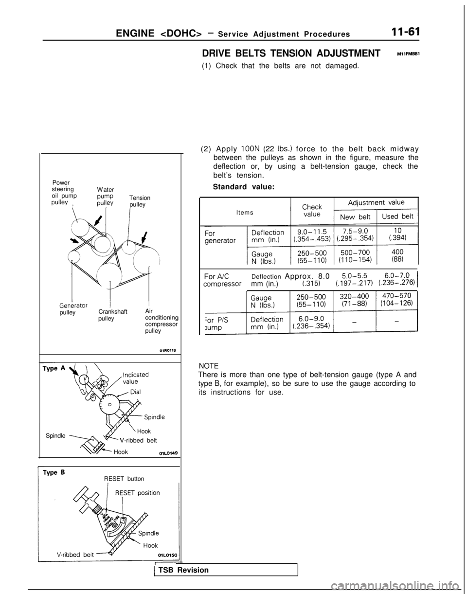
DRIVE BELTS TENSION ADJUSTMENT
MllFMBBl
(1) Check that the belts are not damaged.
Power
steering
oil pump
pulley , W
ater
pump
pulley
Tension
pulley
f /
xI J
b
L ‘d
p1 Genkrator
I
Ipulley
Crankshaft
Air
pulley conditioning
compressor
pulley
Spindle Spindle
2Y
\Hook
xi@--
V-ribbed belt
Hook
r
Type BRESET button (2) Apply
100N (22 Ibs.) force to the belt back midwa
y
between the pulleys as shown in the figure, measure the
deflection or, by using a belt-tension gauge, check the
belt’s tension.
Standard value:
Items
For
AKDeflection Approx. 8.05.0-5.56.0-7.0
comDressormm (in.)t.3151(.197-,217) (.236-.276)I
NOTE
There is more than one type of belt-tension gauge (type A and
type
B, for example), so be sure to use the gauge according to
its instructions for use.
1 TSB Revision
Page 120 of 1273
ENGINE
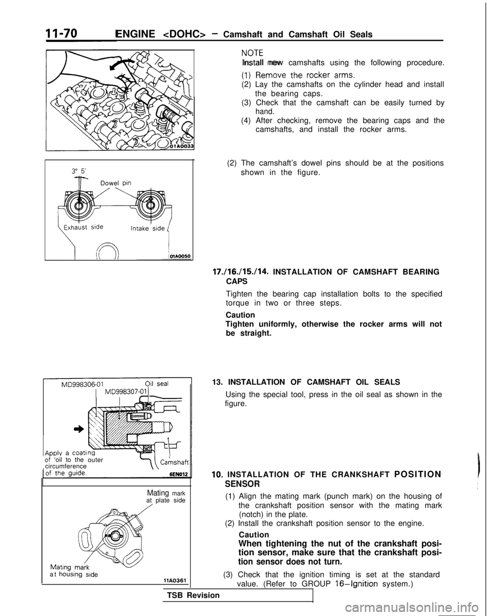
zI?mo”e the rocker arms.
Install new camshafts using the following procedure.
(2) Lay the camshafts on the cylinder head and install the bearing caps.
(3) Check that the camshaft can be easily turned by
hand.
(4) After checking, remove the bearing caps and the camshafts, and install the rocker arms.
3iF-Dowel Din
(2) The camshaft’s dowel pins should be at the positions
shown in the figure.
Intake.side
17./16./15./14. INSTALLATION OF CAMSHAFT BEARING
CAPS
Tighten the bearing cap installation bolts to the specified
torque in two or three steps.
Caution
Tighten uniformly, otherwise the rocker arms will not be straight.
ADDIY a coatioi ‘oil to the outer
circumferenceCahshaft
Mating markat plate side/
at hoising sidellA0361(3) Check that the ignition timing is set at the standard
value. (Refer to GROUP
16-Ignition system.)
TSB Revision 13. INSTALLATION OF CAMSHAFT OIL SEALS
Using the special tool, press in the oil seal as shown in the
figure.
10. INSTALLATION OF THE CRANKSHAFT POSITIO
N
SENSOR
(1) Align the mating mark (punch mark) on the housing of
the crankshaft position sensor with the mating mark(notch) in the plate.
(2) Install the crankshaft position sensor to the engine.
Caution
When tightening the nut of the crankshaft posi-
tion sensor, make sure that the crankshaft posi-
tion sensor does not turn.
Page 138 of 1273
ENGINE
6
@
Plug
6EN0281
Center bolt :
6EN026:-
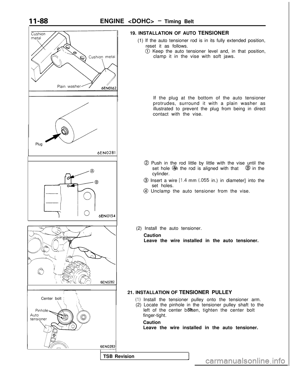
19. INSTALLATION OF AUTO TENSIONER
(1) If the auto tensioner rod is in its fully extended position, reset it as follows.
@I Keep the auto tensioner level and, in that position,clamp it in the vise with soft jaws.
If the plug at the bottom of the auto tensioner
protrudes, surround it with a plain washer as illustrated to prevent the plug from being in direct
contact with the vise.
@ Push in the rod little by little with the vise until the set hole @ in the rod is aligned with that
@I in the
cylinder.
@ Insert a wire Il.4 mm (055 in.) in diameter] into the
set holes.
@I Unclamp the auto tensioner from the vise.
(2) Install the auto tensioner. CautionLeave the wire installed in the auto tensioner.
21. INSTALLATION OF TENSIONER PULLEY
(1) Install the tensioner pulley onto the tensioner arm.
(2) Locate the pinhole in the tensioner pulley shaft to the left of the center bolt. Then, tighten the center bolt
finger-tight.
Caution
Leave the wire installed in the auto tensioner.
TSB Revision
I
Page 141 of 1273
ENGINE
J
Tensioner armTensioner arm
TSB Revision
. ADJUSTMENT OF TIMING BELT TENSION
(1) After turning the crankshaft
l/4 turn counterclockwise,
turn it clockwise to move the No. 1 cylinder to top dead
center.
(2) Loosen the center bolt, and then, as shown in the illustration, attach the special tool and a torque wrench
and apply a torque of 2.6-2.8 Nm (1.88-2.03
ft.lbs.). If
the body interferes with the special tool and the torque
wrench, use a jack to slightly raise the engine assembly.
NOTE
Use a torque wrench that is capable of measurement
within a range of 0- 3 Nm (0- 2.2 ftlbs.).
(3) Holding the tensioner pulley with the special tool and torque wrench, tighten the center bolt to specification.
(4) Screw the tool into the engine left support bracket until its end makes contact with the tensioner arm. At that
point, screw the tool in some more and then remove the
set wire attached to the auto tensioner.
(5) Remove the tool.
(6) Rotate the crankshaft two complete turns clockwise and leave it as is for about 15 minutes. Then, measure
the auto tensioner protrusion “A” (distance between
the tensioner arm and auto tensioner body) to ensure
that it is up to specification.
Standard value: 3.8-4.5 mm
(.15-.I8 in.)
If it is out of specification, repeat steps (6) through (11)
until the specified value is obtained.
(7) If the clearance between the tensioner arm and the auto tensioner body cannot be measured (when the
engine is being mounted, etc.), the following proce-
dures can be used to substitute for the ordinary method
of measurement.
@j Screw in
the tool until it
contacts the tensioner arm.
@From that point of contact, further screw in the tool.
screwing it in
until the push
rod
of the auto
tensioner body is caused to move backward and the
tensioner arm contacts the auto tensioner body.
Check to be sure that the amount that the tool has
been screwed in (when the push rod moves back-
ward) is the standard value.
Standard value:
2.5- 3 turns