set MITSUBISHI GALANT 1989 Service Owner's Manual
[x] Cancel search | Manufacturer: MITSUBISHI, Model Year: 1989, Model line: GALANT, Model: MITSUBISHI GALANT 1989Pages: 1273, PDF Size: 37.62 MB
Page 151 of 1273
FUEL SYSTEM
13-9
r
I Connector
6FU1216
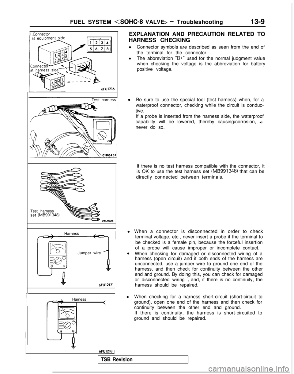
EXPLANATION AND PRECAUTION RELATED TO
HARNESS CHECKING
l Connector symbols are described as seen from the end of
the terminal for the connector.
lThe abbreviation “B+”
used for the normal judgment value
when checking the voltage is the abbreviation for battery positive voltage.
Test harness
set (MB991348)
Jumper wire
&6FU1217
Harness <
LQ
Q,
6FUlZlBj
l
Be sure to use the special tool (test harness) when, for a
waterproof connector, checking while the circuit is conduc-
tive. If a probe is inserted from the harness side, the waterproof
capability will be lowered, thereby causing/corrosion, SO
never do so.
If there is no test harness compatible with the connector, it
is OK to use the test harness set (MB991348)
that can be
directly connected between terminals.
l When a connector is disconnected in order to check terminal voltage, etc., never insert a probe if the terminal to
be checked is a female pin, because the forceful insertion
of a probe will cause improper or incomplete contact.
l When checking for damaged or disconnected wiring of a
harness (open circuit) and if both ends of the harness are
unconnected, use a jumper wire to ground one end of the
harness, and then check for continuity between the other
end and ground. By doing this, you can check for damaged
or disconnected wiring
., and, if there is no continuity, the
harness should be repaired.
l When checking for a harness short-circuit (short-circuit to
ground), open one end of the harness and then check for
continuity between the other end and ground.
If there is continuity, the harness is short-circuited to
ground and should be repaired.
TSB Revision
Page 152 of 1273
13-10
FUEL SYSTEM
at sensor side
1\~“‘,““W,O,’ ‘\*N 4-cnDQ5a,, \llllf,,
c 3 c-11 ‘.<-!
( .[&
;%* \ g ~ &.$$~&%,;
0%: E
.Oj-,,
giI lOWI -,n
/ ~ ( ~~‘-~~~
-.mo .u. m,.0 - rj*> ;;
indicator lamp68AOO93
l
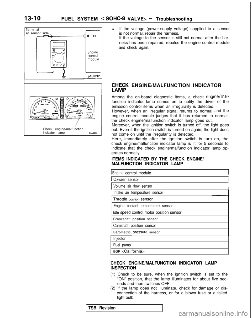
If the voltage (power-supply voltage) supplied to a sensor
is not normal, repair the harness. If the voltage to the sensor is still not normal after the har-
ness has been repaired, repalce the engine control module
and check again.
W&K ENGINE/MALFUNCTION INDICATOR
Among the on-board diagnostic items, a check
engine/mal-
function indicator lamp comes on to notify the driver of the
emission control items when an irregurality is detected. However, when an irregular signal returns to normal
andthe
engine control module judges that it has returned to normal,
the check engine/malfunction indicator lamp goes out. Moreover, when the ignition switch is turned off, the light goes
out. Even if the ignition switch is turned on again, the light does not come on until the irregularity is detected.
Here, immediately after the ignition switch is turn on, the
check engine/malfunction indicator lamp is lit for 5 seconds to indicate that the check engine/malfunction indicator lamp op-
erates normally.
ITEMS INDICATED BY THE CHECK ENGINE/
MALFUNCTION INDICATOR LAMP
1 Enaine control module
IOxvaen sensorI
IVolume air flow sensorIIntake air temperature sensor
Throttle position sensor
Engine coolant temperature sensor
Idle speed control motor position sensor
Crankshaft position sensor
Camshaft position sensor
Barometric rxessure sensor
Injector
Fuel pump
EGR
CHECK ENGINE/MALFUNCTION INDICATOR LAMP
INSPECTION
(1) Check to be sure, when the ignition switch is set to the “ON” position, that the lamp illuminates for about five sec-onds and then switches OFF.
(2) If the lamp does not illuminate, check for damage or dis-
connection of the harness, or for a blown fuse or a failedlight bulb.
TSB Revision
Page 157 of 1273
FUEL SYSTEM
Diagnosti
trouble
code No.
24
25
41
42Set pump
43
iGR;aC;lifor-
COn-board
diagnostic
item
Vehicle
speed
sensor
(reed
switch) 3arometric
Iressuresensor
njector
Diagnostic content
Major cause
During acceleration of engine
revolution speed of 3,000 rpm
or more, the signal voltage of
the vehicle speed sensor doe: not vary (to be high/low). (1) The vehicle speed sensor is
troubled.
(2) Open-circuit, short-circuit or
improper connector contact
occurs in the vehicle speed
sensor circuit.
(1) The signal voltage of the barometric pressure
sensor is 4.5V or higher.
(2) The signal voltage of the barometric pressure
sensor is
0.2V or lower.
Injector is not continuously
driven for 4 seconds during
engine cranking or idle
operation.
The engine runs but power to
irive the motor is not supplied
:o the fuel pump.
luring engine running after Narming-up,
1) The
EGR amount is small.
(The signal voltage of the EGR temperature sensor
is excessively high.)
2) The signal voltage of the
EGR temperature sensor
is 0.1 V or less.
(3) The engine control module is troubled.
1) The barometric pressure sense
is troubled.
2) Open-circuit, short-circuit or
improper connector contact
occurs in the barometric pressure sensor circuit.
‘3) The engine control module is
troubled.
‘1) The injector is troubled.
12) Open-circuit, short-crrcuit
or
improper connector contact
occurs in the injector sensor
circuit.
13) The engine control module is
troubled.
:I) Open-circuit, short-circuit or improper connector contact
occurs in the fuel pump power
supply circuit.
(2) The
multiport fuel injection
relay is troubled.
(3) The engine control module is
troubled.
(1) The EGR valve is not opened.
(2) The negative pressure of the EGR valve control is excessively
(3)
?h”e EGR solenoid is troubled.
(4) The EGR temperature sensor is
troubled.
(5) Open-circuit, short-circuit or
improper connector contact
occurs in the EGR temperature
sensor circuit.
(6) The engine control module is troubled.
r 1l Unstable idling*
l Improper acceleration*
0 Improper start*
l Unstable idling
0 Improper acceleration
0 Improper start
l Impossible start
3 Engine stop4
4
,
B Deterioration of exhaust gaspurifying
performance
Remarks (trouble
phenomenon, etc.)
The engine
sometimes cuts off
when stopping afte
deceleration.
TSB RevisionI
Page 158 of 1273

13-16
FUEL SYSTEM
FAILSAFE/BACK-UP FUNCTIONS LIST
If trouble with any major sensor is detected by the on-board diagnostic,\
the vehicle will be kept in the safe
driving conditions according to the preset control logic.
Trouble item Control content for trouble
Volume air flow Fuel injection timing and ignition timing are determined according to th\
e throttle position
sensor sensor
(TPS) and engine revolution speed signal (crankshaft position sensor signal)\
.
Intake air temperature The control is executed with the suction air temperature regarded as
25°C (77°F).
sensor
Throttle position The fuel injection rate is not increased for acceleration according to t\
he throttle position
sensor
(TPS)sensor signal.
Idle speed control After the idle speed control motor plunger is driven and contracted, the\
idle revolution speed
motor position sensor is not controlled.
Engine coolant The control is executed with the engine coolant temperature regarded as \
8OO.C (176°F).temperature sensor (Even if the sensor signal becomes normal again, the control is continued
until the ignltlon
switch is turned off.)
Camshaft position Simultaneous injection of fuel is executed for all cylinders. (In this \
case, the
No.1 cylinder top
sensor dead center is not detected at all after the ignition key is turned on.)\
Barometric pressure The control is executed with the pressure regarded as 760 mmHg
(30
in.Hg).
sensor
Oxygen sensor Closed loop control of the air/fuel mixture ratio is not executed.
i
READ OUT OF DIAGNOSTIC TROUBLE CODE
Precautions for operation
(1) When battery voltage is low, no detection of failure is possible. Be sure to check the battery for voltage and
other conditions before starting the test.
(2) On-board diagnostic item is erased if the battery or the engine control module connector is discon-
nected. Do not disconnect the battery before the di-
agnostic result is completely read.
Using Scan Tool
(1) Switch OFF the ignition switch.
(2) Connect the power-source terminal of the scan tool to the
cigarette lighter socket.
(3) Connect the scan tool to the data link connector. (4) Turn ignition switch to ON.
(5) Using the scan tool, read out and make a note of the
on-
board diagnostic output.
(6) Refer to the diagnostic chart, and repair the indicated loca-
tion of malfunction.
(7) Erase the diagnostic trouble code. (Refer to
P.13-17.)
1 TSB RevisionI
Page 159 of 1273
FUEL SYSTEM
\ I\-\\\\\\6FUO807
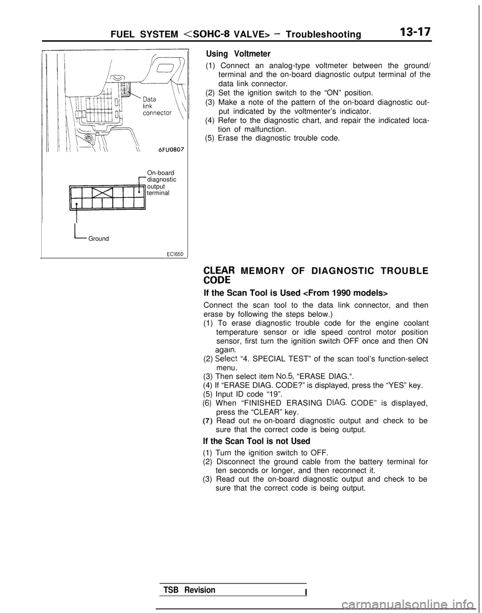
Using Voltmeter
(1) Connect an analog-type voltmeter between the ground/
terminal and the on-board diagnostic output terminal of the
data link connector.
(2) Set the ignition switch to the “ON” position.
(3) Make a note of the pattern of the on-board diagnostic out- put indicated by the voltmenter’s indicator.
(4) Refer to the diagnostic chart, and repair the indicated loca- tion of malfunction.
(5) Erase the diagnostic trouble code.
On-board
diagnostic
output
terminal
LGround
EbLbtR MEMORY OF DIAGNOSTIC TROUBLE
If the Scan Tool is Used
Connect the scan tool to the data link connector, and then
erase by following the steps below.)
(1) To erase diagnostic trouble code for the engine coolant
temperature sensor or idle speed control motor positionsensor, first turn the ignition switch OFF once and then ON
(2) EE?$t
“4. SPECIAL TEST” of the scan tool’s function-select
menu.
(3) Then select item No.5, “ERASE DIAG.“.
(4) If “ERASE DIAG. CODE?” is displayed, press the “YES” k\
ey.
(5) Input ID code “19”.
(6) When “FINISHED ERASING DIAG. CODE” is displayed,> Ipress the “CLEAR” key.
(7) Read out the on-board diagnostic output and check to be
sure that the correct code is being output.
If the Scan Tool is not Used
(1) Turn the ignition switch to OFF.
(2) Disconnect the ground cable from the battery terminal forten seconds or longer, and then reconnect it.
(3) Read out the on-board diagnostic output and check to be
sure that the correct code is being output.
TSB RevisionI
Page 168 of 1273
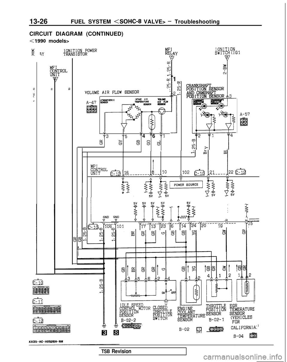
13-26
FUEL SYSTEM
CIRCUIT DIAGRAM (CONTINUED)
(1990 models>
IGNITIONRYSWITCH(IG37
1
4YIGNITION POWERTRANSISTOR
?-
::.?
a,
::
VOLUME AIR FLOW GENSOR
A~rnICnmtit AIRVlEw!A-47 aweal?YPEPAnsleLIP PLOTsetlsmm
\I\/ \, \I “3“5“4 “6 “1
3Fs3d
LI
A-57
.sGi2
MPI
KrTRoL~,1_6_--AL,'10‘I IJO2 g5jj 21----22 &a
”A vVVV
L GND “t?V-
&ario-6
m
4 f 74 I k@J@ ________ -r
i-J101 ~~--~~~-~~~-~--~~-~~~-~20 7-g----- :
r
gt&g
B-02
/-J ,jm’ CALIFORNJ
B-04 m
TSB Revision
Page 174 of 1273
13-32
FUEL SYSTEM
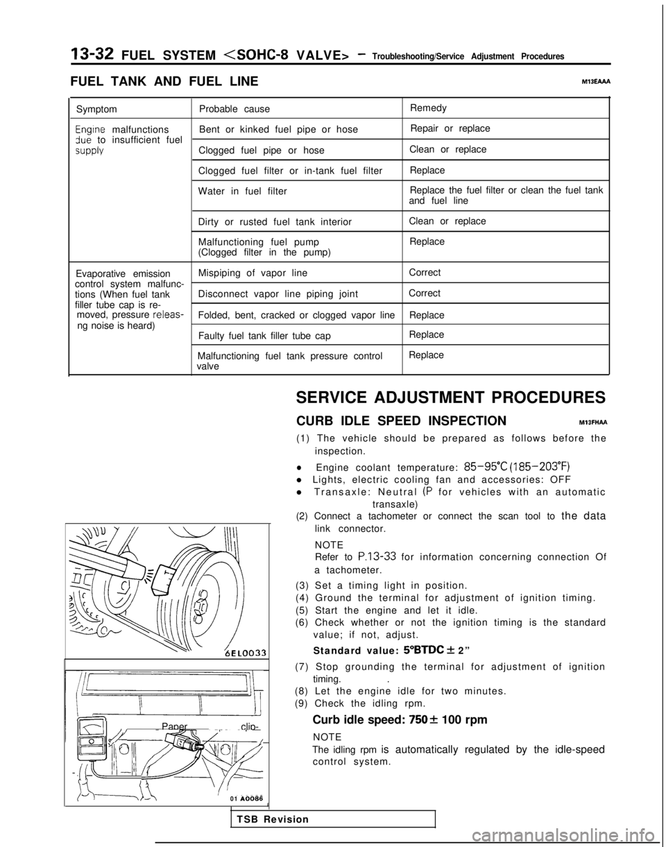
FUEL TANK AND FUEL LINEMlBEAAA
Symptom Probable cause Remedy
Engtne malfunctions
Bent or kinked fuel pipe or hose Repair or replace3ue to insufficient fuel
SUPPlYClogged fuel pipe or hoseClean or replace
Clogged fuel filter or in-tank fuel filter Replace
Water in fuel filter Replace the fuel filter or clean the fuel tank
and fuel line
Dirty or rusted fuel tank interior Malfunctioning fuel pump
(Clogged filter in the pump) Clean or replace
Replace
Evaporative emission Mispiping of vapor line
Correct
control system malfunc-
tions (When fuel tank Disconnect vapor line piping joint Correct
filler tube cap is re- moved, pressure releas-
Folded, bent, cracked or clogged vapor line Replace
ng noise is heard) Faulty fuel tank filler tube cap
Malfunctioning fuel tank pressure control
valve Replace
Replace
LL
m ~~ : Paper clip-
F l!;“I /yFp- -
izd--_7-01
A0086SERVICE ADJUSTMENT PROCEDURES
CURB IDLE SPEED INSPECTION
MlBFHAFt
(1) The vehicle should be prepared as follows before the inspection.
lEngine coolant temperature: 85-95°C (185-203°F)
l Lights, electric cooling fan and accessories: OFF
l Transaxle: Neutral
(P for vehicles with an automatic
transaxle)
(2) Connect a tachometer or connect the scan tool to the data
link connector.
NOTE
Refer to
P.13-33 for information concerning connection Of
a tachometer.
(3) Set a timing light in position.
(4) Ground the terminal for adjustment of ignition timing.
(5) Start the engine and let it idle.
(6) Check whether or not the ignition timing is the standard
value; if not, adjust.
Standard value:
5”BTDC + 2”
(7) Stop grounding the terminal for adjustment of ignition timing. .
(8) Let the engine idle for two minutes.
(9) Check the idling rpm.
Curb idle speed:
7502 100 rpm
NOTE
The idling rpm is automatically regulated by the idle-speed control system.
1
TSB Revision
Page 178 of 1273
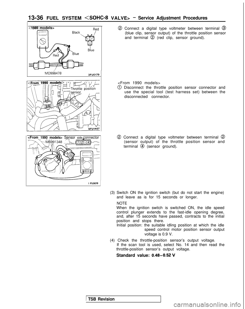
13-36 FUEL SYSTEM
:I989 models>
M
D9684783FUO179
@ Connect a digital type voltmeter between terminal @
(blue clip, sensor output) of the throttle position sensor
and terminal
@I (red clip, sensor ground).
@I Disconnect the throttle position sensor connector and use the special tool (test harness set) between the
disconnected connector.
@ Connect a digital type voltmeter between terminal @
(sensor output) of the throttle position sensor and
terminal
@I (sensor ground).
1 FU0619
(3) Switch ON the ignition switch (but do not start the engine) and leave as is for 15 seconds or longer.
NOTE
When the ignition switch is switched ON, the idle speedcontrol plunger extends to the fast-idle opening degree,
and, after 15 seconds have passed, contracts to the initial
position and stops there.Initial position: the suitable idling position at which the idle speed control motor position sensor output
voltage is 0.9 V.
(4) Check the throttle-position sensor’s output voltage. If the scan tool is used, select No. 14 and then read the
throttle-position sensor’s output voltage.
Standard value: 0.48-0.52
V
1 TSB Revision
Page 189 of 1273
FUEL SYSTEM
OPERATION
l
Activates the fuel pump during engine cranking
and while the engine is running.
l When the ignition switch is set to the START
position, current flows, by way of the
multiport
fuel injection relay coil, from the ignition switch
to ground. As a result, the
multiport fuel injec-
tion relay switch is switched ON, and the power
for activation of the fuel pump is supplied, by
way of the
multiport fuel injection relay switch,
from the battery to the fuel pump.
INSPECTION
Using Scan tool
l While the engine is running, the engine control
module switches ON the power transistor, after
which current flows to the
multiport fuel injec-
tion relay coil, and the power for activation of
the fuel pump is supplied to the fuel pump.
l When the
multiport fuel injection relay switch is
switched ON, battery voltage is also applied to
the engine control module, and so the engine
control module detects the fact that the power
for activation of the fuel pump is being supplied
to the fuel pump.
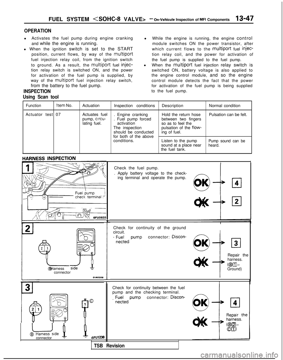
Function Item
No.
Actuation Inspection conditions DescriptionNormal condition
Actuator test 07 Actuates fuel
. Engine cranking Hold the return hosePulsation can be felt.
pump, clrcu-
. Fuel pump forced between two fingers
lating fuel. activation
so as to feel the
The inspection pulsation of the
flow-should be conducteding of fuel.
for both of the above conditions. Listen to the pump
Pump sound can besound at a place nearheard.the fuel tank.
Check for continuity of the ground
circuit.
I
. ;E;;,, pumpconnector: Discon-
2
1
Y-
!
Repair theharness.
@El- @ HarnessGround)connector
O~AOZOl3
I
Check for continuity between the fuel
pump and the checking terminal.
connector: Discon-
1
@uide 1
B
0. ;;;;,,
pump
L
Check the fuel pump.
. Apply battery voltage to the check-
ing terminal and operate the pump.
!I:7
OK
connector :1 = 6FUl238
TSB Revision
Page 219 of 1273
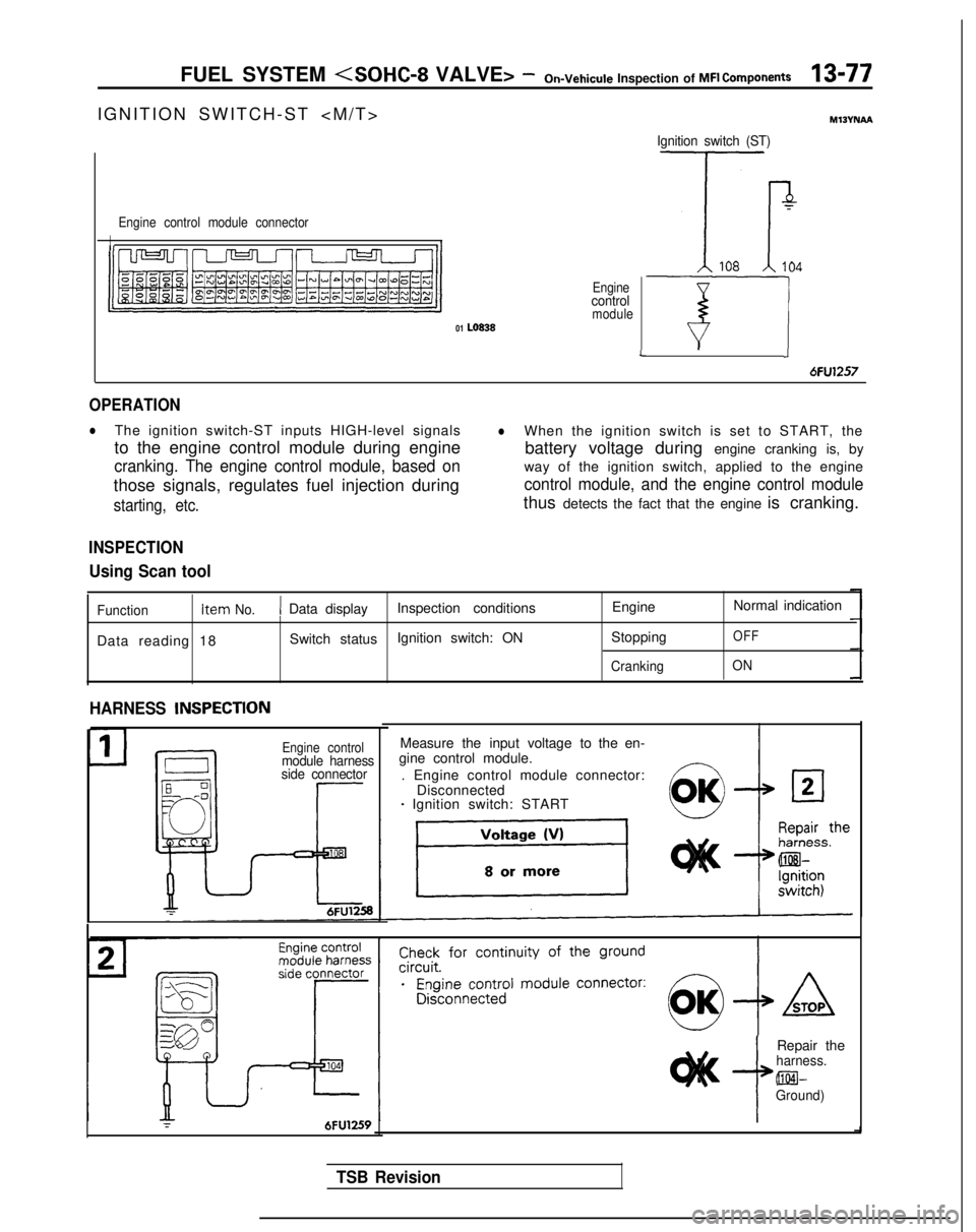
FUEL SYSTEM
IGNITION SWITCH-ST
>
Engine control module connector
II
Enginecontrolmodule01 LO838
Ignition switch (ST)
7
Tr108104
T-7JL
6FU1257
OPERATION
lThe ignition switch-ST inputs HIGH-level signalslWhen the ignition switch is set to START, the
to the engine control module during engine battery voltage during engine cranking is, by
cranking. The engine control module, based onway of the ignition switch, applied to the engine
those signals, regulates fuel injection during
control module, and the engine control module
starting, etc.thus detects the fact that the engine is cranking.
INSPECTION
Using Scan tool
Function Item No.1 Data display
Inspection conditions EngineNormal indication
Data reading 18 Switch status
Ignition switch: ON
Stopping
OFF
CrankingON
HARNESS INSPECTlON
Engine controlmodule harness
side connector
Measure the input voltage to the en-
gine control module.
. Engine control module connector: Disconnected
- Ignition switch: START
r6FU1259i
Repair theharness. @El-
Ground)
TSB Revision