set MITSUBISHI GALANT 1989 Service Service Manual
[x] Cancel search | Manufacturer: MITSUBISHI, Model Year: 1989, Model line: GALANT, Model: MITSUBISHI GALANT 1989Pages: 1273, PDF Size: 37.62 MB
Page 335 of 1273
FUEL SYSTEM
TerminaNo.
19
52
-rII
i
t
c
65
L
63
64t
I:
I
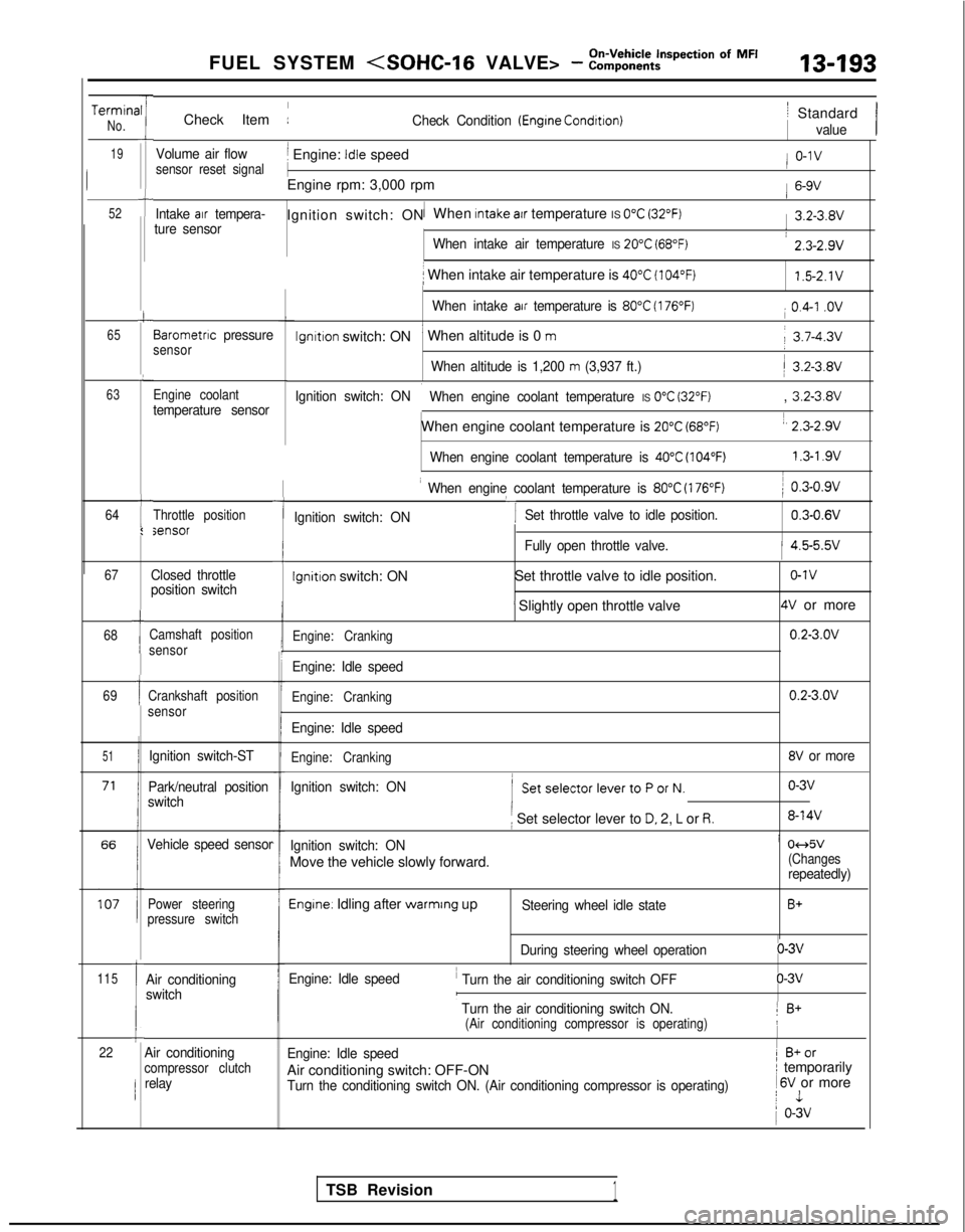
Check Item :Check Condition (Engrne Condrtron)
Volume air flowj Engine: Idle speedsensor reset signal
1
Engine rpm: 3,000 rpm
Intake air tempera-1Ignition switch: ON When Intake atr temperature IS 0°C (32°F)ture sensor
When intake air temperature IS 20°C (68°F)
i When intake air temperature is 40°C (104°F)
When intake air temperature is 80°C (176°F)
lgnltlon switch: ON’ When altitude is 0 m
When altitude is 1,200 m (3,937 ft.)
Ignition switch: ON
i When engine coolant temperature IS 0°C (32°F)
When engine coolant temperature is 20°C (68°F)
When engine coolant temperature is 40°C (104°F)
Barometnc pressuresensor
Engine coolant
temperature sensor
Throttle positionsensor
67
68
69
51
115
1
1
Ic22
Closed throttle
position switch
Camshaft position
sensor
Crankshaft position
sensor
Ignition switch-ST
Park/neutral position
switch
Vehicle speed sensor
Power steering
pressure switch
Air conditioning
switch
-I
I When engine coolant temperature is 80°C (176°F)
‘I
) 0.3-0.9v
Ignition switch: ON Set throttle valve to idle position.
0.3-0.6V
iFully open throttle valve.1 4.5-5.5v
Ignition switch: ON
Set throttle valve to idle position.o-1v
’ Slightly open throttle valve4V or more
Engine: Cranking0.2-3.OV
Engine: Idle speed
Engine: Cranking0.2-3.OV
Engine: Idle speed
Engine: Cranking8V or more
Ignition switch: ON
( SetselectorlevertoPorN.o-3v
i Set selector lever to D. 2, L or R.8-14V
Ignition switch: ONi 04d5v
Move the vehicle slowly forward.(Changesrepeatedly)
Engine. Idling after warmrng upSteering wheel idle stateB+
During steering wheel operationo-3v
Engine: Idle speed
’ Turn the air conditioning switch OFFo-3vI
’ Turn the air conditioning switch ON.1 B+(Air conditioning compressor is operating)!
Engine: Idle speed1 B+or
Air conditioning switch: OFF-ONI temporarily
Turn the conditioning switch ON. (Air conditioning compressor is operat\
ing) 1
6V or morej 1
1 o-3v
/ Standard
value
/ o-1v
1 6-9V
1 3.2-3.8V
: 2.3-2.9v
1.5-2.1V
i 0.4-I .ov
j 3.7-4.3v
/ 3.2-3.8V
, 3.2-3.8V
1, 2.3-2.9v
1.3-l .9vI
Air conditioningcompressor clutchrelay
TSB Revision1
Page 347 of 1273
FUEL SYSTEM
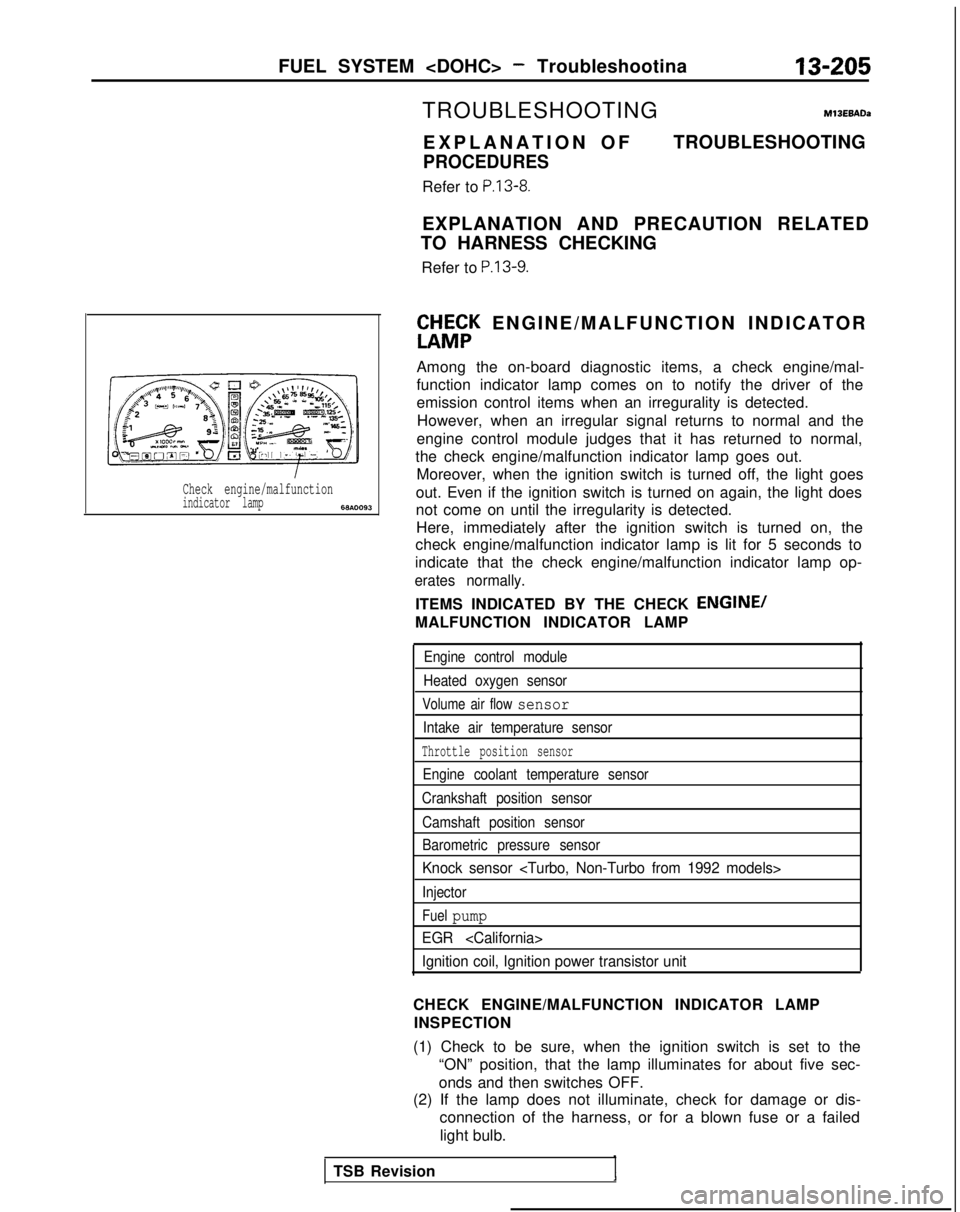
Check engine/malfunctionindicator lamp6w.0093
TROUBLESHOOTINGM13EBADa
EXPLANATION O
F
PROCEDURES
Refer to P.13-8.
TROUBLESHOOTING
EXPLANATION AND PRECAUTION RELATED
TO HARNESS CHECKING
Refer to
P.13-9.
ft&;K ENGINE/MALFUNCTION INDICATO
R
Among the on-board diagnostic items, a check engine/mal-
function indicator lamp comes on to notify the driver of the
emission control items when an irregurality is detected. However, when an irregular signal returns to normal and the
engine control module judges that it has returned to normal,
the check engine/malfunction indicator lamp goes out. Moreover, when the ignition switch is turned off, the light goes
out. Even if the ignition switch is turned on again, the light does
not come on until the irregularity is detected. Here, immediately after the ignition switch is turned on, the
check engine/malfunction indicator lamp is lit for 5 seconds to
indicate that the check engine/malfunction indicator lamp op-
erates normally.
ITEMS INDICATED BY THE CHECK ENGINE/
MALFUNCTION INDICATOR LAMP
Engine control module
Heated oxygen sensor
Volume air flow sensor
Intake air temperature sensor
Throttle position sensor
Engine coolant temperature sensor
Crankshaft position sensor
Camshaft position sensor
Barometric pressure sensor
Knock sensor
Injector
Fuel pump
EGR
Ignition coil, Ignition power transistor unit
CHECK ENGINE/MALFUNCTION INDICATOR LAMP INSPECTION
(1) Check to be sure, when the ignition switch is set to the “ON” position, that the lamp illuminates for about five sec-
onds and then switches OFF.
(2) If the lamp does not illuminate, check for damage or dis-
connection of the harness, or for a blown fuse or a failed
light bulb.
TSB Revision
Page 353 of 1273

FUEL SYSTEM
FAILSAFE/BACK-UP FUNCTIONS LIST
If trouble with any major sensor is detected by the on-board diagnostic,\
the vehicle will be kept in the safe
driving conditions-accdrding
to the preset control
logic.
Trouble item
Volume air flow
sensor Control content for trouble
(1) Fuel injection timing and ignition timing are determined according\
to the throttle positior
sensor (TPS) and engine revolution speed signal (crankshaft position \
sensor signal).
(2) The idle air control motor is fixed at the specified position, and\
the idle revolution speec
control is not executed.
Intake air
temperature sensor The control is executed with the suction air temperature regarded as
25’C (77°F).
Throttle positron
sensor (TPS)The fuel injection rate is not increased for acceleration according to t\
he throttle positionsensor signal.
Engine coolant
temperature sensor The control IS executed with the engine coolant temperature regarded as 80°C
(176°F).(Even if the sensor signal becomes normal again, the control is continu\
ed until the ignition
switch is turned off.)
Camshaft position
sensor (1) Simultaneous injection of fuel is executed for all cylinders.
(In this case, the No.
1 cylinder top dead center is not detected at all after the ignition
key is turned on.)
(2) Fuel is cut 4 seconds after trouble is detected. (In this case, the No. 1 cylinder top dead center IS not detected at all after the ignition
key is turned on.)
Barometric pressure
sensor The control is executed with the pressure regarded as 760
mmHg (30 in.Hg.).
Knocksensor
The ignition timing is retarded further from the normal state, and ignit\
ion is executed even
when knocking does not occur.
Ignition coil, ignition
power transistor unitFuel is cut in the cylinder where the ignition signal is abnormal.
Heated oxygen sensor Closed loop control of the air/fuel mixture ratio is not executed.
TSB RevisionREAD OUT OF DIAGNOSTIC TROUBLE CODE
Refer to
P.13-16.
CLEAR MEMORY OF DIAGNOSTIC TROUBLE
CODE
Refer to P.13-17.
Page 387 of 1273
FUEL SYSTEM
cl989 models> -a’i\.-upI t
SERVICE ADJUSTMENT PROCEDURES
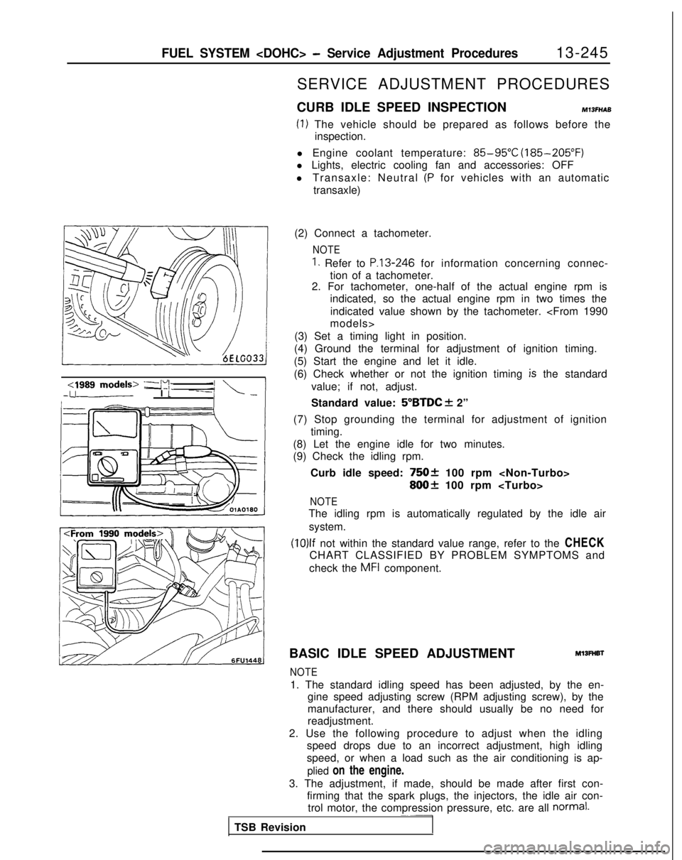
CURB IDLE SPEED INSPECTION
MlSFHAB
(1) The vehicle should be prepared as follows before the inspection.
l Engine coolant temperature:
85-95°C (185-205°F)
l Lights, electric cooling fan and accessories: OFF
l Transaxle: Neutral
(P for vehicles with an automatic
transaxle)
(2) Connect a tachometer.
NOTE
1. Refer to P.13-246 for information concerning connec-
tion of a tachometer.
2. For tachometer, one-half of the actual engine rpm is
indicated, so the actual engine rpm in two times the
indicated value shown by the tachometer.
(3) Set a timing light in position.
(4) Ground the terminal for adjustment of ignition timing.
(5) Start the engine and let it idle.
(6) Check whether or not the ignition timing
is the standard
value; if not, adjust.
Standard value:
5”BTDC f 2”
(7) Stop grounding the terminal for adjustment of ignition timing.
(8) Let the engine idle for two minutes.
(9) Check the idling rpm.
Curb idle speed:
75Ok 100 rpm
800+ 100 rpm
NOTE
The idling rpm is automatically regulated by the idle airsystem.
(10)lf not within the standard value range, refer to the CHECK
CHART CLASSIFIED BY PROBLEM SYMPTOMS and
check the
MFI component.
BASIC IDLE SPEED ADJUSTMENT
Ml3FHBl
NOTE
1. The standard idling speed has been adjusted, by the en- gine speed adjusting screw (RPM adjusting screw), by the
manufacturer, and there should usually be no need for
readjustment.
2. Use the following procedure to adjust when the idling speed drops due to an incorrect adjustment, high idling
speed, or when a load such as the air conditioning is ap-
plied on the engine.
3. The adjustment, if made, should be made after first con- firming that the spark plugs, the injectors, the idle air con-trol motor, the compression pressure, etc. are all
normal.~~-
TSB Revision
Page 391 of 1273
FUEL SYSTEM
13-249
<1989 models> /zz Throttle position
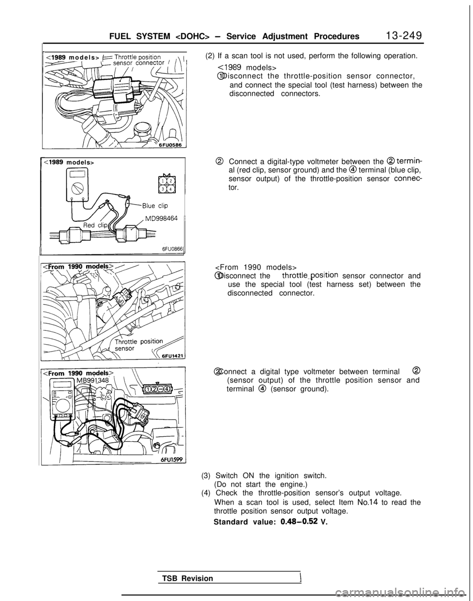
(2) If a scan tool is not used, perform the following operation.,-
~1989 models> @ Disconnect the throttle-position sensor connector,
and connect the special tool (test harness) between the
disconnected connectors.
:1989 models>@Connect a digital-type voltmeter between the @ termin-
al (red clip, sensor ground) and the @I terminal (blue clip,
sensor output) of the throttle-position sensor connec-
tor.
Blue
clip
throttle.position sensor connector and
use the special tool (test harness set) between the
disconnected connector. @ Connect a digital type voltmeter between terminal @
(sensor output) of the throttle position sensor and
terminal
@ (sensor ground).
(3) Switch ON the ignition switch. (Do not start the engine.)
(4) Check the throttle-position sensor’s output voltage.
When a scan tool is used, select Item
No.14 to read the
throttle position sensor output voltage.
Standard value:
0.48-0.52 V.
TSB Revision
I
Page 400 of 1273
k.
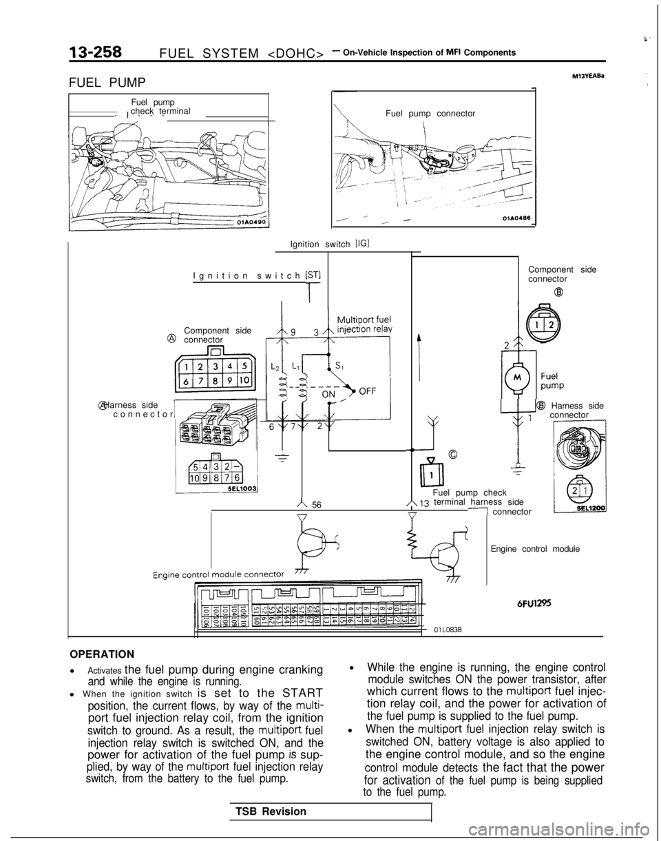
13-258FUEL SYSTEM
FUEL PUMP Fuel pump
check terminal
-I--
-
Ignition switch
[r
Ignition switch [IGI @
Component side
connector @ Harness side
Iconnecto
r
Fuel pump connector
I
,- __ _ /OlAO488
-T
IComponent side
connector
@
h 56 @
Harness side
1
v y
connector
-NC-
lrll
0
1-z
Fuel pump checkA 13 terminal harness
side-1 connector
I Engine
control
module
connector
Engine control module
6FU1295
01 LO838
OPERATION
l
Activates the fuel pump during engine cranking
and while the engine is running.
l When the ignition switch is set to the START
position, the current flows, by way of the multi-
port fuel injection relay coil, from the ignition
switch to ground. As a result, the multiport fuel
injection relay switch is switched ON, and the
power for activation of the fuel pump is sup-
plied, by way of the multiport fuel injection relay
switch, from the battery to the fuel pump.
lWhile the engine is running, the engine control module switches ON the power transistor, after
which current flows to the multiport fuel injec-
tion relay coil, and the power for activation of
the fuel pump is supplied to the fuel pump.
lWhen the multiport fuel injection relay switch is
switched ON, battery voltage is also applied to
the engine control module, and so the engine
control module detects the fact that the power
for activation of the fuel pump is being supplied
to the fuel pump.
TSB Revision
Page 403 of 1273
FUEL SYSTEM
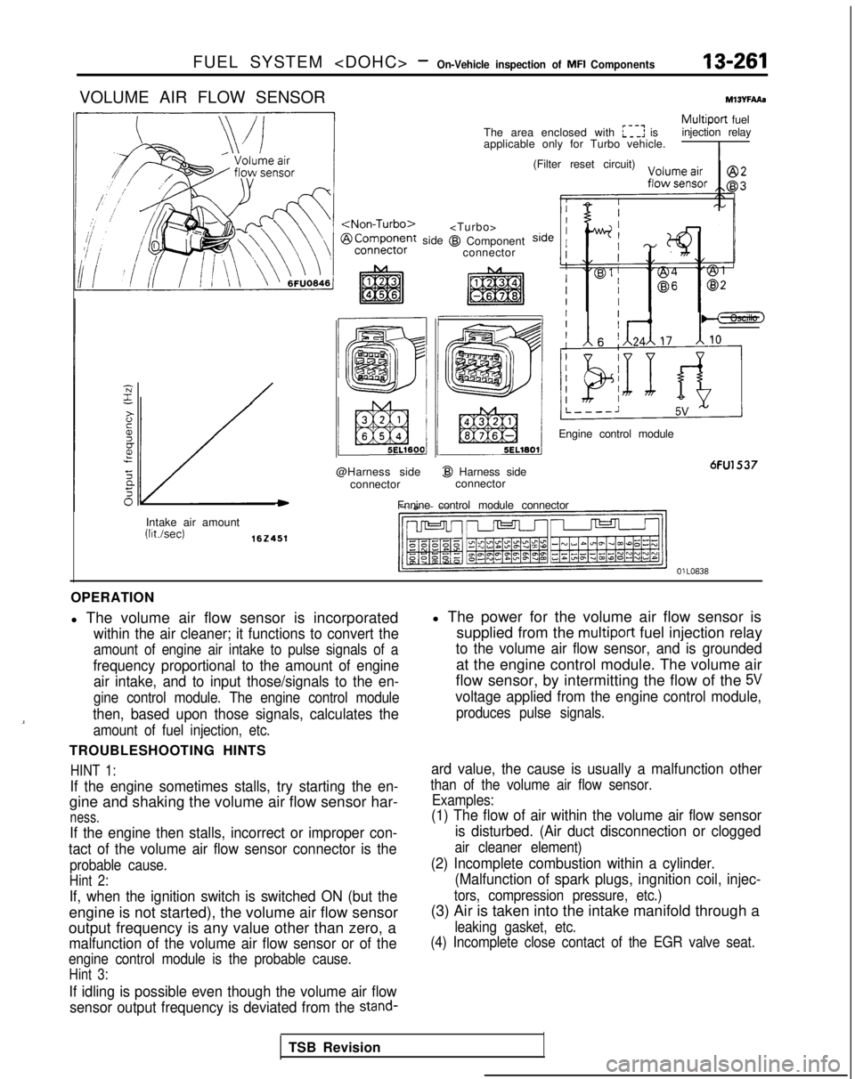
VOLUME AIR FLOW SENSORMlWFAAs
/
side
@Harness side connector
I@ Harness sideconnector
Fnnine control module connector
Multiport fuel
The area enclosed with :I: is injection relay
applicable only for Turbo vehicle.
I
@I Component connector (Filter reset circuit)
Engine control module
6FU1537
Intake air amount (Wsec)
162451
OlLO838
OPERATION
l The volume air flow sensor is incorporated
within the air cleaner; it functions to convert the
amount of engine air intake to pulse signals of a
frequency proportional to the amount of engine air intake, and to input those/signals to the en-
gine control module. The engine control module
then, based upon those signals, calculates the
amount of fuel injection, etc.
TROUBLESHOOTING HINTS
HINT 1:
If the engine sometimes stalls, try starting the en-
gine and shaking the volume air flow sensor har-
ness.
If the engine then stalls, incorrect or improper con-
tact of the volume air flow sensor connector is the
probable cause.
Hint 2:
If, when the ignition switch is switched ON (but the
engine is not started), the volume air flow sensor
output frequency is any value other than zero, a
malfunction of the volume air flow sensor or of the
engine control module is the probable cause.
Hint 3:
If idling is possible even though the volume air flow
sensor output frequency is deviated from the
stand-
l The power for the volume air flow sensor is supplied from the
multiport fuel injection relay
to the volume air flow sensor, and is grounded
at the engine control module. The volume air
flow sensor, by intermitting the flow of the
5V
voltage applied from the engine control module,
produces pulse signals.
ard value, the cause is usually a malfunction other
than of the volume air flow sensor. Examples:
(1) The flow of air within the volume air flow sensor
is disturbed. (Air duct disconnection or clogged
air cleaner element)
(2) Incomplete combustion within a cylinder.(Malfunction of spark plugs, ingnition coil, injec-
tors, compression pressure, etc.)
(3) Air is taken into the intake manifold through a
leaking gasket, etc.
(4) Incomplete close contact of the EGR valve seat.
TSB Revision
Page 445 of 1273
r
FUEL SYSTEM
of
MFI Components13-303
INSPECTION
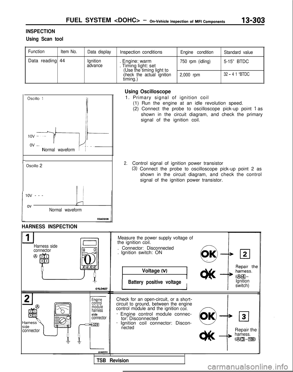
Using Scan tool
Function Item No.
Data reading 44
Data displayInspection conditionsEngine condition Standard value
Ignition
advance
. Engine: warm
. Timing light: set750 rpm (idling)5-15” BTDC
(Use the timing light to
check the actual ignition 2,000 rpm32 - 4 1 “BTDCtiming.)
Oscillo 1
Normal waveform
Oscilio 2
!
1ov --
-
ovNormal waveform
HARNESS INSPECTION
Harness side
connectorE 0-0
J
El0
connectorI
lEnginecontrol
module
harness
sideconnector
Using Oscilloscope
1. Primary signal of ignition coil
(1) Run the engine at an idle revolution speed.
(2) Connect the probe to oscilloscope pick-up point
1 as
shown in the circuit diagram, and check the primary
signal of the ignition coil.
2.Control signal of ignition power transistor
(3) Connect the probe to oscilloscope pick-up point 2 as
shown in the circuit diagram, and check the control
signal of the ignition power transistor.
Measure the power supply voltage ofthe ignition coil.
. Connector: Disconnected. Ignition switch: ON
Voltage (VI
IBattery positive voltageIIIgnitionswitch)
Check for an open-circuit, or a
short-circuit to ground, between the engine
control module and the ignition coil.
* Engine control module connec- tor: Disconnected
* Ignition coil connector: Discon-nected
i
Repair theharness.
N23l3k-m)
TSB Revision
Page 458 of 1273
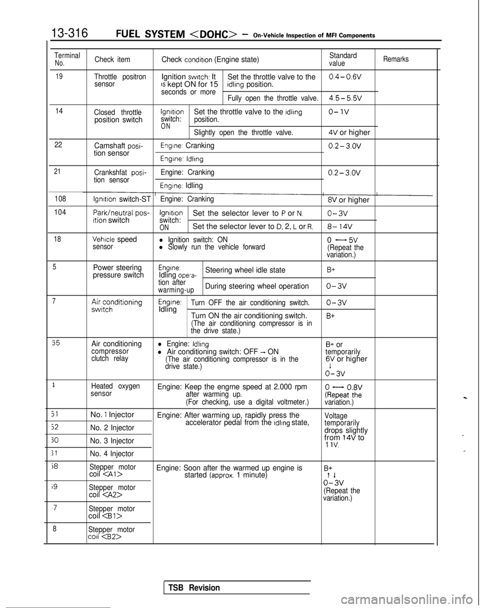
13-316FUEL SYSTEM
Inspection
of
MFI
Components
TerminalNo.Check itemCheck condition (Engine state)Standardvalue
Remarks
19Throttle positronIgnition switch: ItSet the throttle valve to the0.4- 0.wsensorIS kept ON for 15seconds or moreidlrng position.
Fully open the throttle valve.4.5- 5.5v
14
Closed throttlelgnrtrono-1vposition switchswitch:Set the throttle valve to the idling
position.
ONSlightly open the throttle valve.4V or higher
22Camshaft posi-tion sensorEngine: Cranking0.2- 3.ov
Engine: ldlrng
21
Crankshfat posi-tion sensor Engine: Cranking0.2- 3.ov
Engine: Idling
108lgnrtion switch-STEngine: Cranking8V or higher
104
Park/neutral
pos-ition switchIgnitionSet the selector lever to P or N.o-3vswitch:ONSet the selector lever to D, 2, L or R.8- 14V
18Vehicle speedl Ignition switch: ON
sensorl Slowly run the vehicle forward0 - 5v(Repeat the
variation.)
5Power steering
pressure switchEngine:Idling opera-Steering wheel idle stateB+
tion afterwarming-upDuring steering wheel operationo-3v
7A&;;;ditioningEngine:Idling _Turn OFF the air conditioning switch.o-3v
Turn ON the air conditioning switch.B+
(The air conditioning compressor is in
the drive state.)
35Air conditioningl Engine: IdlingB+ orcompressor
clutch relayl Air conditioning switch: OFF -, ON(The air conditioning compressor is in the
temporarily
drive state.)6V or higher o’-
3v
1Heated oxygen
sensorEngine: Keep the engrne speed at 2.000 rpmafter warming up.
(For checking, use a digital voltmeter.)ke;atoZivariation.)
51No. 1 InjectorEngine: After warming up, rapidly press the
52No. 2 Injector accelerator pedal from the idlrng state,Voltage
temporarily
drops slightly
30No. 3 Injectorfrom 14V to1 IV.
51No. 4 Injector
j8
Stepper motorcoil
i9
Stepper motor0%
coil
variation.)
‘7Stepper motorcoil
8Stepper motorco11
TSB Revision
Page 474 of 1273
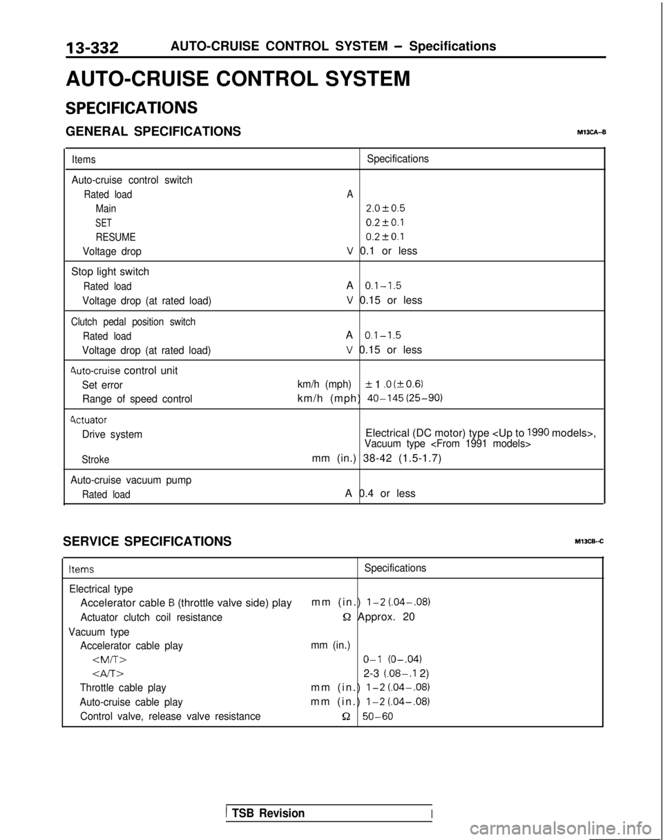
13-332
AUTO-CRUISE CONTROL SYSTEM - Specifications
AUTO-CRUISE CONTROL SYSTEM
SPECIFICATIONS
GENERAL SPECIFICATIONSM13CA--B
Items
Auto-cruise control switch
Rated load Main
SET
RESUME
Voltage drop
Stop light switch
Rated load
Voltage drop (at rated load)
Clutch pedal position switch
Rated load
Voltage drop (at rated load)
4uto-cruise control unit
Set errorRange of speed control
4ctuator
Drive system
Stroke
Auto-cruise vacuum pump
Rated load
Specifications
A
2.0f0.5
0.2fO.l 0.2t-0.1
V 0.1 or less
A
0.1-1.5
V 0.15 or less
A
0.1-1.5
V 0.15 or less
km/h (mph)IL 1 .O (kO.6)
km/h (mph) 40-145
(25-90)
Electrical (DC motor) type
mm (in.) 38-42 (1.5-1.7)
A 0.4 or less
SERVICE SPECIFICATIONS
Ml3CB-.C
ItemsSpecifications
Electrical type
Accelerator cable B (throttle valve side) play mm (in.) l-2 (.04-.08)
Actuator clutch coil resistanceQ Approx. 20
Vacuum type
Accelerator cable play mm (in.)
Gv-r~2-3 (.08-.I 2)
Throttle cable playmm (in.) l-2 (.04-.08)
Auto-cruise cable playmm (in.) l-2
(.04-.08)
Control valve, release valve resistance52 50-60
1 TSB RevisionI