check oil MITSUBISHI GALANT 1989 Service Owner's Manual
[x] Cancel search | Manufacturer: MITSUBISHI, Model Year: 1989, Model line: GALANT, Model: MITSUBISHI GALANT 1989Pages: 1273, PDF Size: 37.62 MB
Page 88 of 1273
11-38
ENGINE
Rubber
exposed
Tooth missing
and
canvas fiber exposed
lEN0002
Crankshaft
sprocket “B”
Crankshaft
aENzo4
Spacer
Chamfered
6EN009
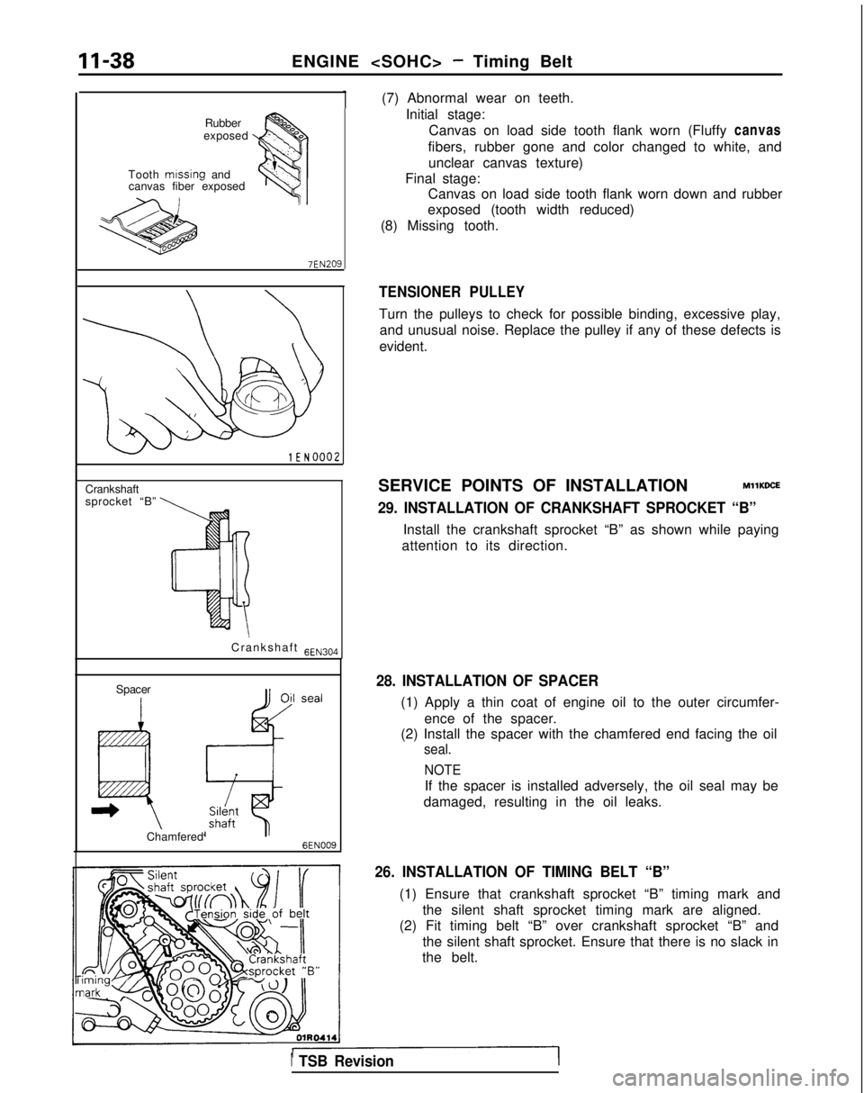
(7) Abnormal wear on teeth.Initial stage:Canvas on load side tooth flank worn (Fluffy canvas
fibers, rubber gone and color changed to white, and unclear canvas texture)
Final stage: Canvas on load side tooth flank worn down and rubber
exposed (tooth width reduced)
(8) Missing tooth.
TENSIONER PULLEY
Turn the pulleys to check for possible binding, excessive play, and unusual noise. Replace the pulley if any of these defects is
evident.
SERVICE POINTS OF INSTALLATION
MllKDCE
29. INSTALLATION OF CRANKSHAFT SPROCKET “B”
Install the crankshaft sprocket “B” as shown while paying
attention to its direction.
28. INSTALLATION OF SPACER
(1) Apply a thin coat of engine oil to the outer circumfer-
ence of the spacer.
(2) Install the spacer with the chamfered end facing the oil
seal.
NOTE
If the spacer is installed adversely, the oil seal may be
damaged, resulting in the oil leaks.
26. INSTALLATION OF TIMING BELT “B”
(1) Ensure that crankshaft sprocket “B” timing mark and the silent shaft sprocket timing mark are aligned.
(2) Fit timing belt “B” over crankshaft sprocket “B” and
the silent shaft sprocket. Ensure that there is no slack in
the belt.
1 TSB Revision
Page 90 of 1273
II-40ENGINE
OlRO372
1(3) Move tensioner fully toward water pump and tempo-rarily secure tensioner.
Timing mark Timing mark
(on cylinder head)
Timing mark
“1(on front case) ,A.
Timing mark6EN063
3ENOO5
Tensiorof belt-I sid
e
Tension side of belt
6EN0065
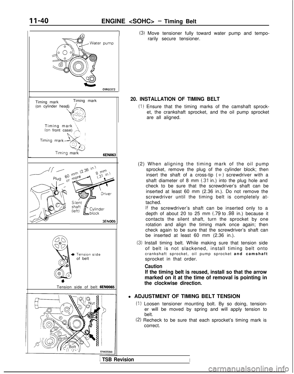
20. INSTALLATION OF TIMING BELT
(1) Ensure that the timing marks of the camshaft sprock- et, the crankshaft sprocket, and the oil pump sprocket
are all aligned.
(2) When aligning the timing mark of the oil pump sprocket, remove the plug of the cylinder block; then
insert the shaft of a cross-tip
(+) screwdriver with a
shaft diameter of 8 mm
(.31 in.) into the plug hole and
check to be sure that the screwdriver’s shaft can be
inserted at least 60 mm (2.36 in.). Do not remove the
screwdriver until the timing belt is completely at-
tached.
If the screwdriver’s shaft can be inserted only to a
depth of about 20 to 25 mm
(.79 to .98 in.) because it
contacts the silent shaft, turn the sprocket by one rotation and align the timing mark once again; then
check again to be sure that the screwdriver’s shaft can be inserted at least 60 mm (2.36 in.).
(3) Install timing belt. While making sure that tension side
of belt is not slackened, install timing belt onto
crankshaft sprocket, oil pump sprocket and camshaf
t
sprocket in that order.
Caution
If the timing belt is reused, install so that the arrow
marked on it at the time of removal is pointing in
the clockwise direction.
l ADJUSTMENT OF TIMING BELT TENSION
(1) Loosen tensioner mounting bolt. By so doing, tension- er will be moved by spring and will apply tension to
belt.
(2) Recheck to be sure that each sprocket’s timing mark iscorrect.
1 TSB RevisionI
Page 91 of 1273
ENGINE
I
I
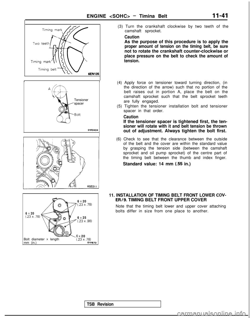
(3) Turn the crankshaft clockwise by two teeth of the
camshaft sprocket.
Caution
As the purpose of this procedure is to apply the
proper amount of tension on the timing belt, be sure
not to rotate the crankshaft counter-clockwise or
place pressure on the belt to check the amount of
tension.
Tensioner
spacer
OlR0404
(4) Apply force on tensioner toward turning direction, (inthe direction of the arrow) such that no portion of the
belt raises out in portion A, place the belt on the
camshaft sprocket such that the belt sprocket teeth
are fully engaged.
(5) Tighten the tensioner installation bolt and tensioner spacer in that order.
Caution
If the tensioner spacer is tightened first, the ten-
sioner will rotate with it and belt tension be thrown
out of adjustment. Always tighten the bolt first.
TSB Revision
(6) Check to see that the clearance between the outside of the belt and the cover are within the standard value
by grasping the tension side (between the camshaft
sprocket and oil pump sprocket) of the centre part of
the timing belt between the thumb and index finger.
Standard value: 14 mm
(.55 in.)
6 x 20(23 x .78)
6 x 20(23 x .78)
6 x 25t.23 x ,981
11. INSTALLATION OF TIMING BELT FRONT LOWER COV- ER/9.
TIMING BELT FRONT UPPER COVER
Note that the timing belt lower and upper cover attaching
bolts differ in size from one place to another.
Bolt diameter
x length
mm (in.)6x 20t.23 x ,781011672
Page 94 of 1273
ENGINE
A Timing
mark
Timingmark
mark
-/Crank&aft swocketOlA0667 lEN0017SERVICE POINTS OF REMOVAL
MllKBDG
2. REMOVAL OF ENGINE MOUNT BRACKET
(1) With a wooden block placed against the oil pan part ofthe engine, jack up the vehicle.
Caution
Jack up gently, so as not to apply a load to the va-
rious parts.
(2) Remove the engine mount bracket.
11. REMOVAL OF AUTO TENSIONER
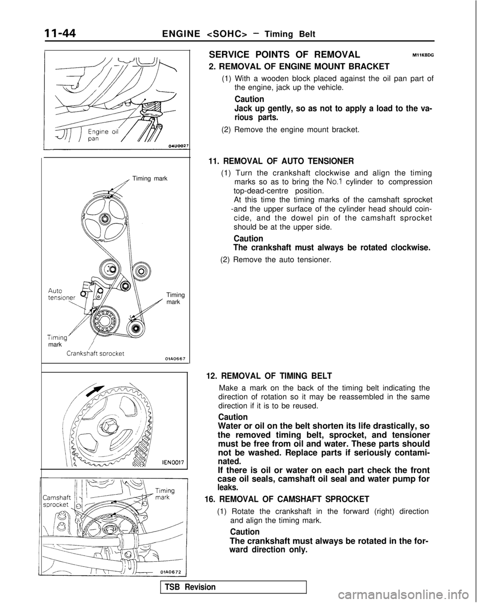
(1) Turn the crankshaft clockwise and align the timing marks so as to bring the
No.1 cylinder to compression
top-dead-centre position. At this time the timing marks of the camshaft sprocket
-and the upper surface of the cylinder head should coin- cide, and the dowel pin of the camshaft sprocket
should be at the upper side.
Caution
The crankshaft must always be rotated clockwise.
(2) Remove the auto tensioner.
12. REMOVAL OF TIMING BELT
Make a mark on the back of the timing belt indicating the
direction of rotation so it may be reassembled in the same
direction if it is to be reused.
Caution
Water or oil on the belt shorten its life drastically, so
the removed timing belt, sprocket, and tensioner must be free from oil and water. These parts should
not be washed. Replace parts if seriously contami-
nated.
If there is oil or water on each part check the front
case oil seals, camshaft oil seal and water pump for
leaks.
16. REMOVAL OF CAMSHAFT SPROCKET
(1) Rotate the crankshaft in the forward (right) direction
and align the timing mark.
Caution
The crankshaft must always be rotated in the for-
ward direction only.
TSB Revision
Page 95 of 1273
ENGINE
11-45
sprocket
vlGVO001 MD998754
vlB990767-01
-
&
00B00°
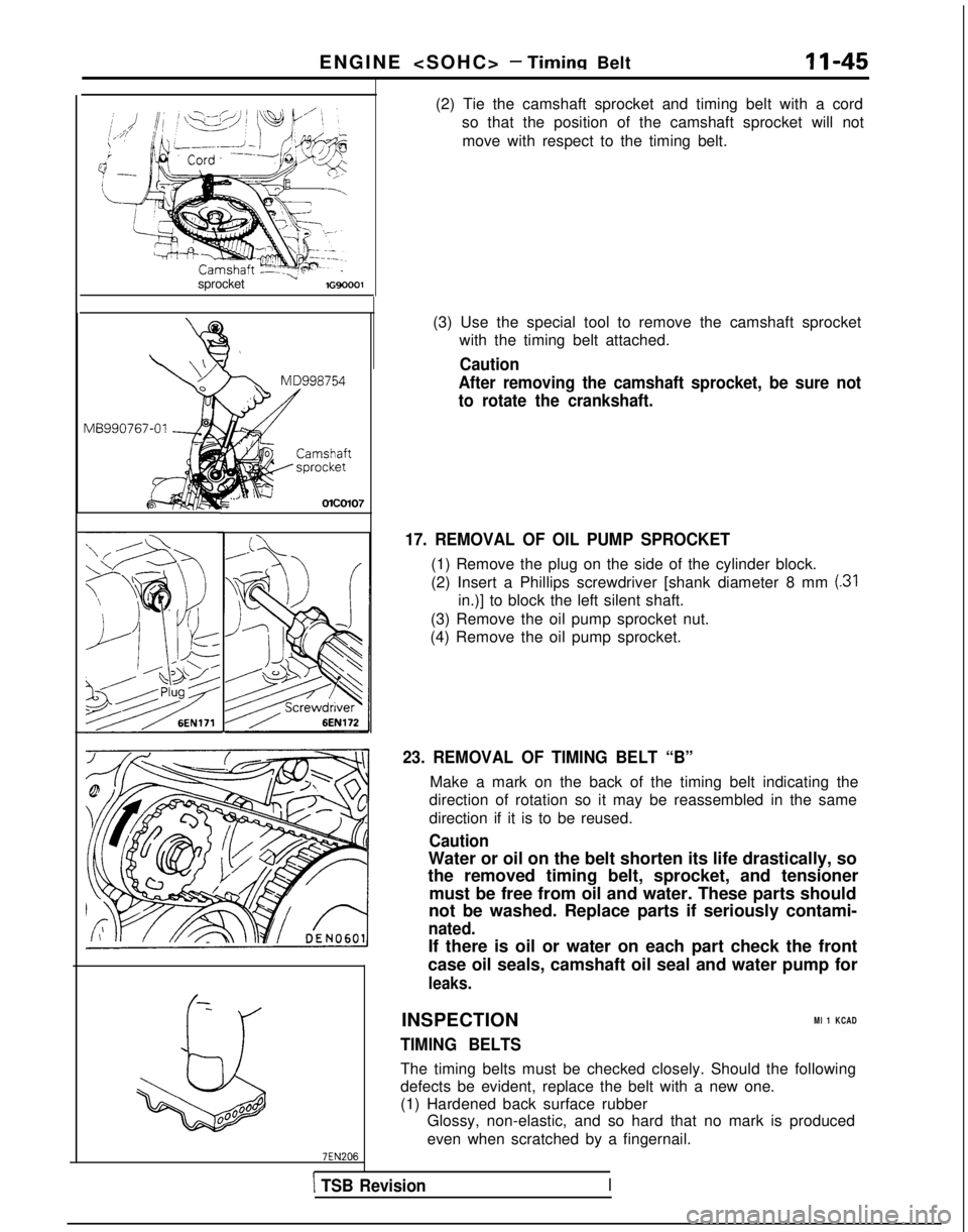
(2) Tie the camshaft sprocket and timing belt with a cord
so that the position of the camshaft sprocket will not
move with respect to the timing belt.
(3) Use the special tool to remove the camshaft sprocket with the timing belt attached.
Caution
After removing the camshaft sprocket, be sure not
to rotate the crankshaft.
17. REMOVAL OF OIL PUMP SPROCKET
(1) Remove the plug on the side of the cylinder block.
(2) Insert a Phillips screwdriver [shank diameter 8 mm
(31
in.)] to block the left silent shaft.
(3) Remove the oil pump sprocket nut.
(4) Remove the oil pump sprocket.
23. REMOVAL OF TIMING BELT “B”
Make a mark on the back of the timing belt indicating the
direction of rotation so it may be reassembled in the same
direction if it is to be reused.
Caution
Water or oil on the belt shorten its life drastically, so
the removed timing belt, sprocket, and tensioner
must be free from oil and water. These parts should
not be washed. Replace parts if seriously contami-
nated.
If there is oil or water on each part check the front
case oil seals, camshaft oil seal and water pump for
leaks.
INSPECTIONMl 1 KCAD
TIMING BELTS
The timing belts must be checked closely. Should the following
defects be evident, replace the belt with a new one.
(1) Hardened back surface rubber Glossy, non-elastic, and so hard that no mark is produced
even when scratched by a fingernail.
\ TSB RevisionI
Page 100 of 1273
ENGINE
Center bolt i\ \
6EN028:
Timina mark
Timingmark
Timing mark
Crankshaft sprocket
OlAO668
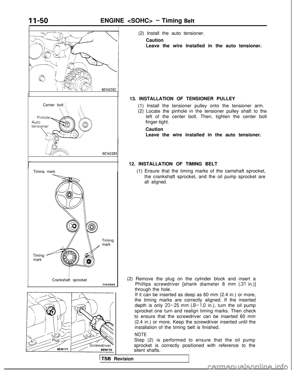
(2) Install the auto tensioner.Caution
Leave the wire installed in the auto tensioner.
13. INSTALLATION OF TENSIONER PULLEY (1) Install the tensioner pulley onto the tensioner arm.
(2) Locate the pinhole in the tensioner pulley shaft to the left of the center bolt. Then, tighten the center bolt
finger-tight.
Caution
Leave the wire installed in the auto tensioner.
12. INSTALLATION OF TIMING BELT (1) Ensure that the timing marks of the camshaft sprocket,the crankshaft sprocket, and the oil pump sprocket are
all aligned.
(2) Remove the plug on the cylinder block and insert a Phillips screwdriver [shank diameter 8 mm
(.31 in.)]
through the hole. If it can be inserted as deep as 60 mm (2.4 in.) or more,
the timing marks are correctly aligned. If the inserted
depth is only
20-25 mm (.8-1.0 in.), turn the oil pump
sprocket one turn and realign timing marks. Then check
to ensure that the screwdriver can be inserted 60 mm (2.4 in.) or more. Keep the screwdriver inserted until theinstallation of the timing belt is finished.
NOTE
Step (2) is performed to ensure that the oil pump
sprocket is correctly positioned with reference to the
silent shafts.
1 TSB Revision
Page 107 of 1273
ENGINE
OlR0340
7EN0393
1SERVICE ADJUSTMENT PROCEDUBFzo
ENGINE OIL CHECK
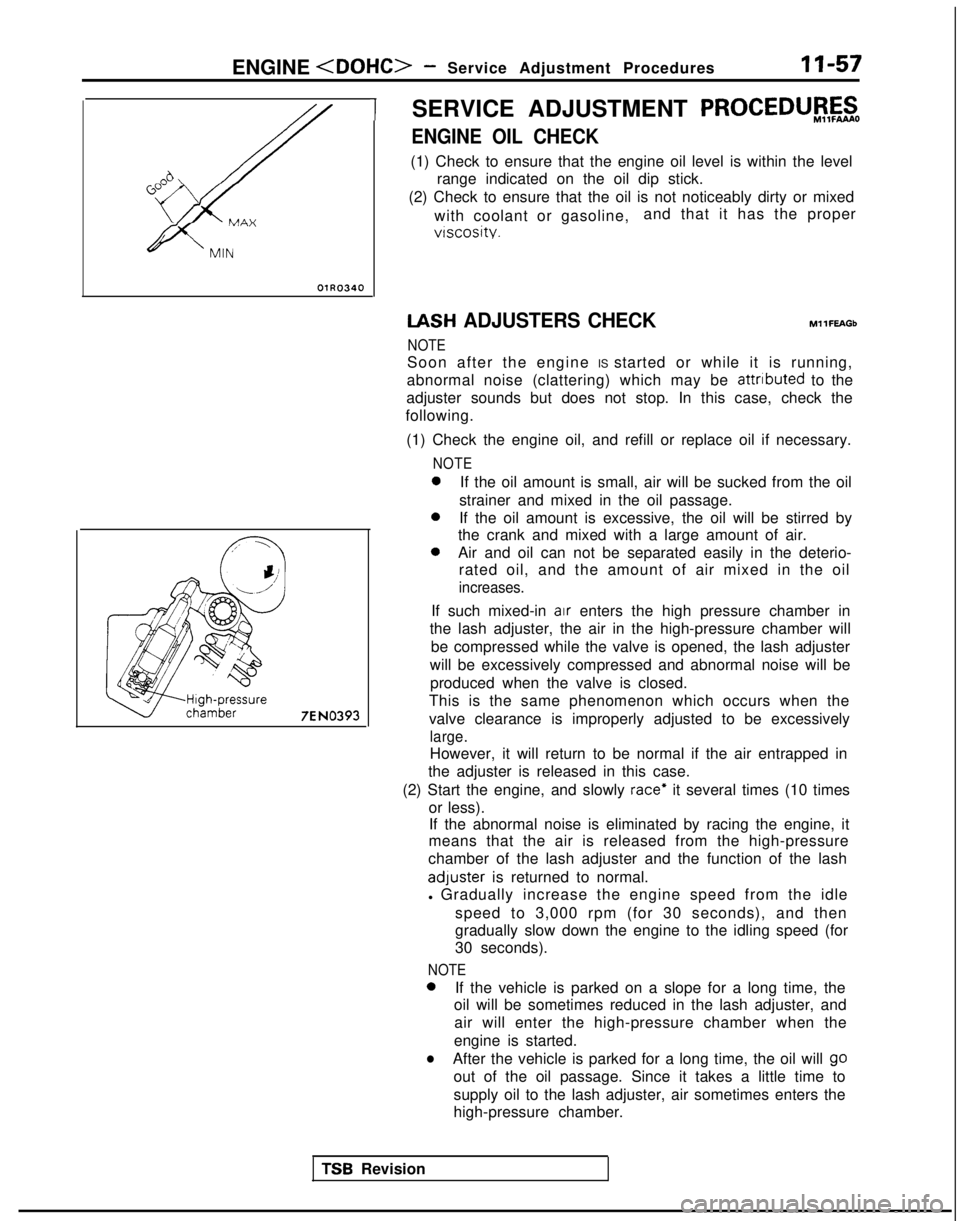
(1) Check to ensure that the engine oil level is within the level
range indicated on the oil dip stick.
(2) Check to ensure that the oil is not noticeably dirty or mixed
with coolant or gasoline, and that it has the proper
vtscosity. IASH
ADJUSTERS CHECK
NOTE MllFEAGb
Soon after the engine IS started or while it is running,
abnormal noise (clattering) which may be attributed
to the
adjuster sounds but does not stop. In this case, check the
following.
(1) Check the engine oil, and refill or replace oil if necessary.
NOTE 0
If the oil amount is small, air will be sucked from the oil
strainer and mixed in the oil passage. 0
If the oil amount is excessive, the oil will be stirred by
the crank and mixed with a large amount of air. 0
Air and oil can not be separated easily in the deterio-
rated oil, and the amount of air mixed in the oil
increases.
If such mixed-in air enters the high pressure chamber in
the lash adjuster, the air in the high-pressure chamber will
be compressed while the valve is opened, the lash adjuster
will be excessively compressed and abnormal noise will be produced when the valve is closed.
This is the same phenomenon which occurs when the
valve clearance is improperly adjusted to be excessively
large.
However, it will return to be normal if the air entrapped in
the adjuster is released in this case.
(2) Start the engine, and slowly
race* it several times (10 times
or less). If the abnormal noise is eliminated by racing the engine, it
means that the air is released from the high-pressure
chamber of the lash adjuster and the function of the lash adluster
is returned to normal.
l Gradually increase the engine speed from the idle
speed to 3,000 rpm (for 30 seconds), and then
gradually slow down the engine to the idling speed (for
30 seconds).
NOTE 0
If the vehicle is parked on a slope for a long time, the
oil will be sometimes reduced in the lash adjuster, and
air will enter the high-pressure chamber when the
engine is started.
lAfter the vehicle is parked for a long time, the oil will go
out of the oil passage. Since it takes a little time to
supply oil to the lash adjuster, air sometimes enters the
high-pressure chamber.
TSR Revision
Page 109 of 1273
ENGINE
7 Go;;ikv position
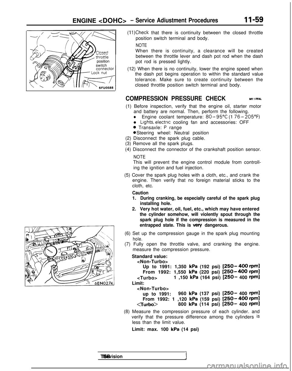
switch
(11)Check that there is continuity between the closed throttle
position switch terminal and body.
NOTE
When there is continuity, a clearance will be created between the throttle lever and dash pot rod when the dash
pot rod is pressed lightly.
(12) When there is no continuity, lower the engine speed when the dash pot begins operation to within the standard value
tolerance. Make sure to create continuity between the
closed throttle position switch terminal and body.
COMPRESSION PRESSURE CHECK Ml 1 FFAL
(1) Before inspection, verify that the engine oil, starter motor
and battery are normal. Then, perform the following.
lEngine coolant temperature: 80- 95°C
(1 76- 205’F)
l Lights, electnc
cooling fan and accessories: OFF
0 Transaxle: P range 0 Steering wheel: Neutral position
(2) Disconnect the spark plug cable.
(3) Remove all the spark plugs.
(4) Disconnect the connector of the crankshaft position sensor.
NOTE
This will prevent the engine control module from controll- ing the ignition and fuel injection.
(5) Cover the spark plug holes with a cloth, etc., and crank the engine. Then verify that no foreign material sticks to the
cloth, etc.
Caution
1.During cranking, be especially careful of the spark plug
installing hole.
2. Very hot water, oil, fuel, etc., which may have entered
the cylinder somehow, will violently spout through the
spark plug hole if the compression is measured in the
entrapped state. This is
vex/ dangerous.
(6) Set up the compression gauge in the spark plug mounting
hole.
(7) Fully open the throttle valve, and cranking the engine.
measure the compression pressure.
Standard value:
kPa (192 psi) [250- 400 rpml
From 1992: 1,550
kPa (220 psi) [250-400 rpm]
Limit:
up to 1991: 960
kPa (137 psi) [250- 400 rpml
From 1992: 1 ,120 kPa (159 psi) [250- 400 rpml
CTurbo>
800
kPa (114 psi) [250- 400 rpml
(8) Measure the compression pressure of each cylinder. and verify that the pressure difference among the cylinders
is
less than the limit value.
Limit: max. 100
kPa (14 psi) TSB Revision
I
Page 110 of 1273
II-60ENGINE
(9) If a cylinder’s compression pressure or pressure differenceis outside the limit, fill a small amount of engine oil through
the spark plug hole and repeat Items (7) and (8) above.
@ If the compression is increased when the oil is filled, the piston
and/or cylinder wall may be worn or
damaged.
@ If the compression is not Increased even though the oil is filled, the valve may be thermally seized, the valve
contact may be improper or pressure may leak at the
gasket. (10)Connect the connector of the crankshaft position sensor.
(1l)lnstall
the spark plug and spark plug cable.
(12)Erase the diagnostic trouble code with the scan tool or re-
connect the battery (-)
cable 10 seconds or more after it
was disconnected.
NOTE
This will erase the memory of the diagnostic trouble code which resulted from disconnection of the crankshaft posi-
tion sensor connector.
MANIFOLD VACUUM INSPECTION MllFNAD
(1) Before inspection and adjustment, put the vehicle into the following state.
l Engine coolant temperature:
85-95°C (185-205°F)
l Lights, motor cooling fan, and accessories: OFF
l Transaxle:
N (Neutral)
l Steering wheel: Neutral
(2) Check that the idling revolution speed is normal.
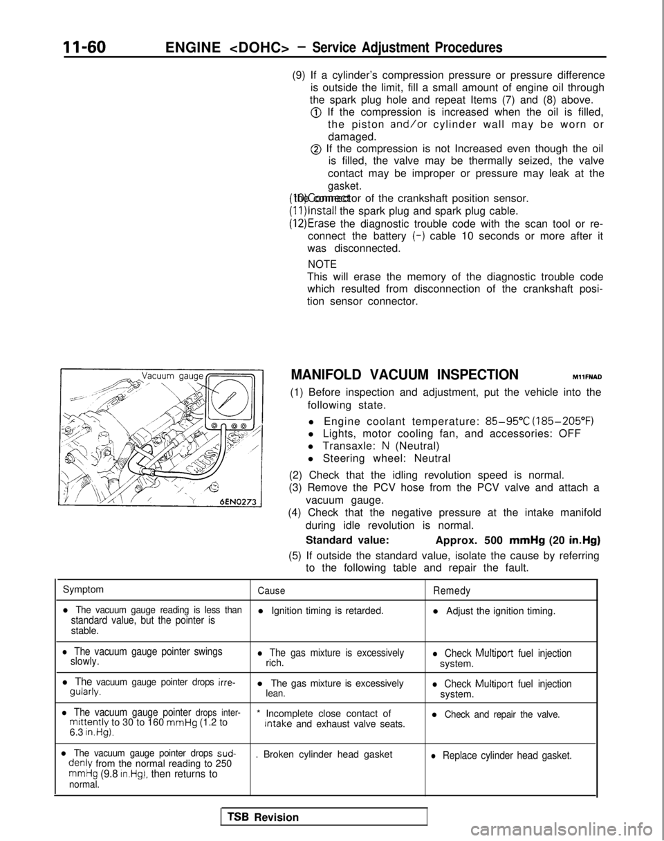
(3) Remove the PCV hose from the PCV valve and attach a
vacuum gauge.
(4) Check that the negative pressure at the intake manifold
during idle revolution is normal.
Standard value: Approx. 500 mmHg
(20 in.Hg)
(5) If outside the standard value, isolate the cause by referring to the following table and repair the fault.
Symptom
CauseRemedy
l The vacuum gauge reading is less thanstandard value, but the pointer isl Ignition timing is retarded. l Adjust the ignition timing.
stable.
l The vacuum gauge pointer swings
slowly.l The gas mixture is excessivelyrich.l Check Multiport fuel injectionsystem.
l The vacuum gauge pointer drops irre- gularly.
l The gas mixture is excessively
lean.l Check Multiport
fuel injectionsystem.
l The vacuum gauge pointer drops inter-mittently to 30 to 160 mmHg
(1.2 to * Incomplete close contact of Intake
and exhaust valve seats.l Check and repair the valve.
6.3 in.Hg).
l The vacuum gauge pointer drops sud- denly
from the normal reading to 250 . Broken cylinder head gasketl Replace cylinder head gasket.
mmHg (9.8 in.Hg), then returns tonormal.
TSB Revision
Page 111 of 1273
ENGINE
DRIVE BELTS TENSION ADJUSTMENT
MllFMBBl
(1) Check that the belts are not damaged.
Power
steering
oil pump
pulley , W
ater
pump
pulley
Tension
pulley
f /
xI J
b
L ‘d
p1 Genkrator
I
Ipulley
Crankshaft
Air
pulley conditioning
compressor
pulley
Spindle Spindle
2Y
\Hook
xi@--
V-ribbed belt
Hook
r
Type BRESET button (2) Apply
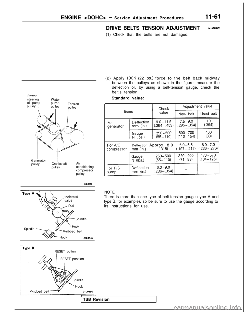
100N (22 Ibs.) force to the belt back midwa
y
between the pulleys as shown in the figure, measure the
deflection or, by using a belt-tension gauge, check the
belt’s tension.
Standard value:
Items
For
AKDeflection Approx. 8.05.0-5.56.0-7.0
comDressormm (in.)t.3151(.197-,217) (.236-.276)I
NOTE
There is more than one type of belt-tension gauge (type A and
type
B, for example), so be sure to use the gauge according to
its instructions for use.
1 TSB Revision