check oil MITSUBISHI GALANT 1989 Service Service Manual
[x] Cancel search | Manufacturer: MITSUBISHI, Model Year: 1989, Model line: GALANT, Model: MITSUBISHI GALANT 1989Pages: 1273, PDF Size: 37.62 MB
Page 180 of 1273
13-38
FUEL SYSTEM
ON-VEHICLE INSPECTION OF MFI
COMPONENTS
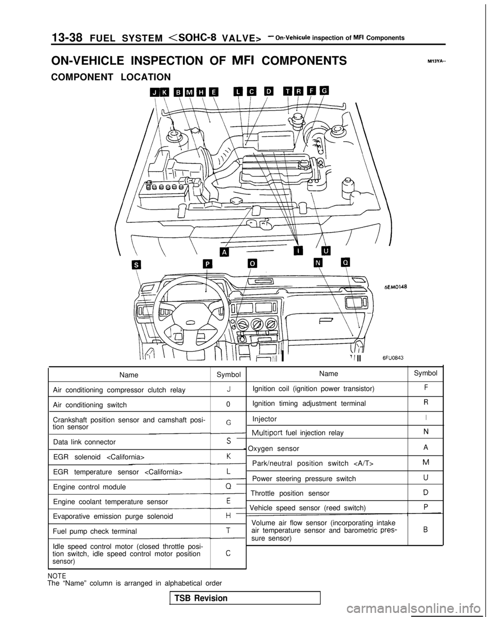
COMPONENT LOCATION
Ii111 I‘I 1 II
bEM0148
6FUO843
M?BYA-
Name Symbol Name
Symbol
Air conditioning compressor clutch relay
JIgnition coil (ignition power transistor)F
Air conditioning switch 0Ignition timing adjustment terminalR
Crankshaft position sensor and camshaft posi- InjectorIGtion sensor-Multiport fuel injection relayN
Data link connectorS - Oxygen sensor
A
EGR solenoid
K-Park/neutral position switch M
EGR temperature sensor
L-Power steering pressure switchU
Engine control moduleQ- Throttle position sensorD
Engine coolant temperature sensorE- Vehicle speed sensor (reed switch)P
Evaporative emission purge solenoidHVolume air flow sensor (incorporating intake
Fuel pump check terminalTair temperature sensor and barometric pres-B
-sure sensor)
Idle speed control motor (closed throttle posi-
tion switch, idle speed control motor position
Csensor)
NOTEThe “Name” column is arranged in alphabetical order
TSB Revision
Page 184 of 1273
13-42 FUEL SYSTEM
(9) Switch OFF the ignition switch. (10)Disconnect
the scan tool. (11)Restart
the engine and perform a driving test, etc. to
confirm that the malfunction has been corrected.
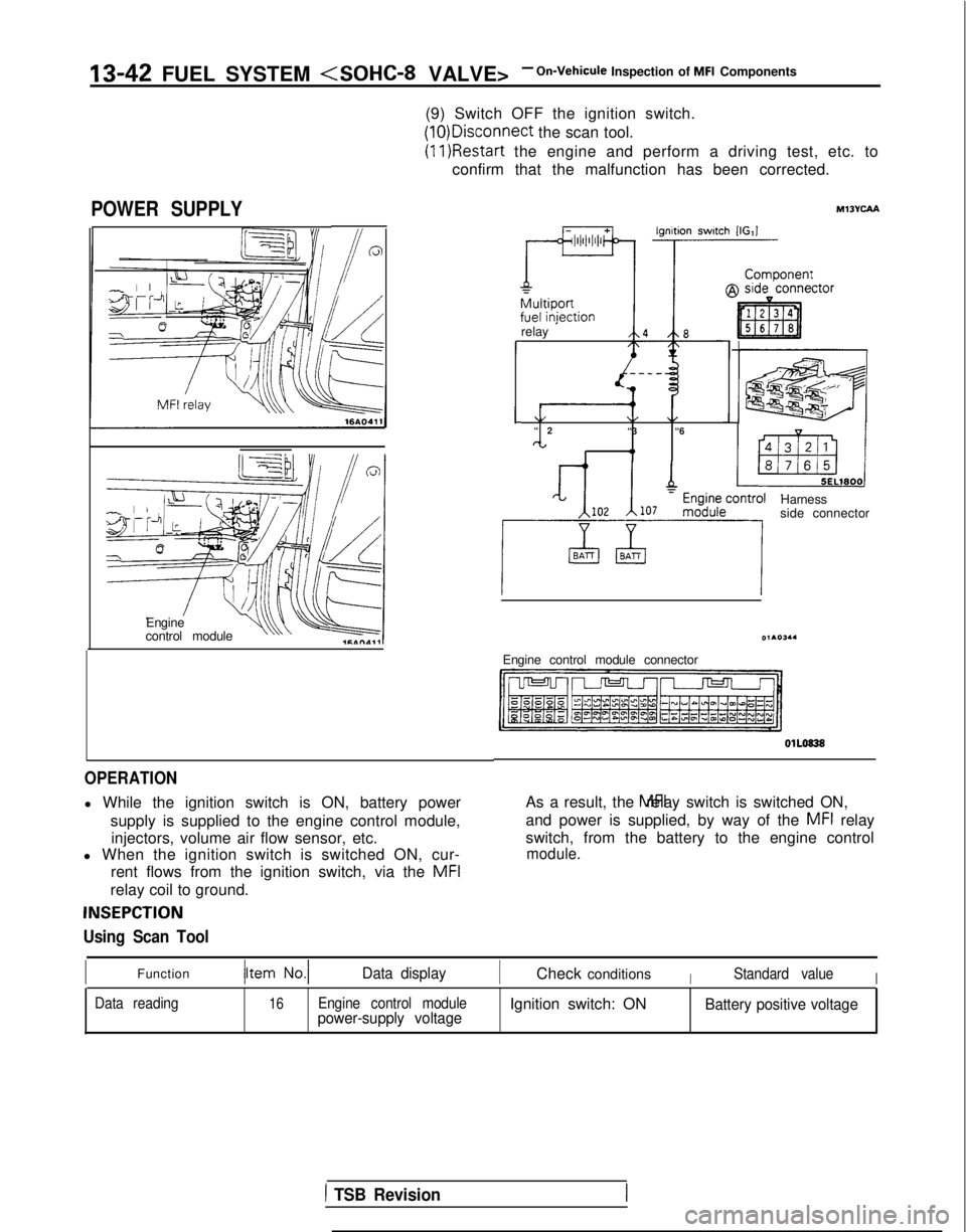
POWER SUPPLY
Engine
control moduleu\\ v
OPERATION
l While the ignition switch is ON, battery power
supply is supplied to the engine control module,injectors, volume air flow sensor, etc.
l When the ignition switch is switched ON, cur-
rent flows from the ignition switch, via the MFI
relay coil to ground.
INSEPCTION
Using Scan Tool
relay ’
\/\/\/“
2
“3 “6
CL I 4,
Harness
side connector
Engine control module connector OlLO838
As a result, the MFI relay switch is switched ON,
and power is supplied, by way of the
MFI relay
switch, from the battery to the engine control
module.
IFunctionData displayICheck conditionsIStandard valueI
Data reading16Engine control modulepower-supply voltageIgnition switch: ONBattery positive voltage
1 TSB Revision
Page 186 of 1273
‘13-44 FUEL SYSTEM
EC1163
When applying battery voltage directly, make sure that it
is applied to correct terminal. Otherwise, the relay could
be damaged.
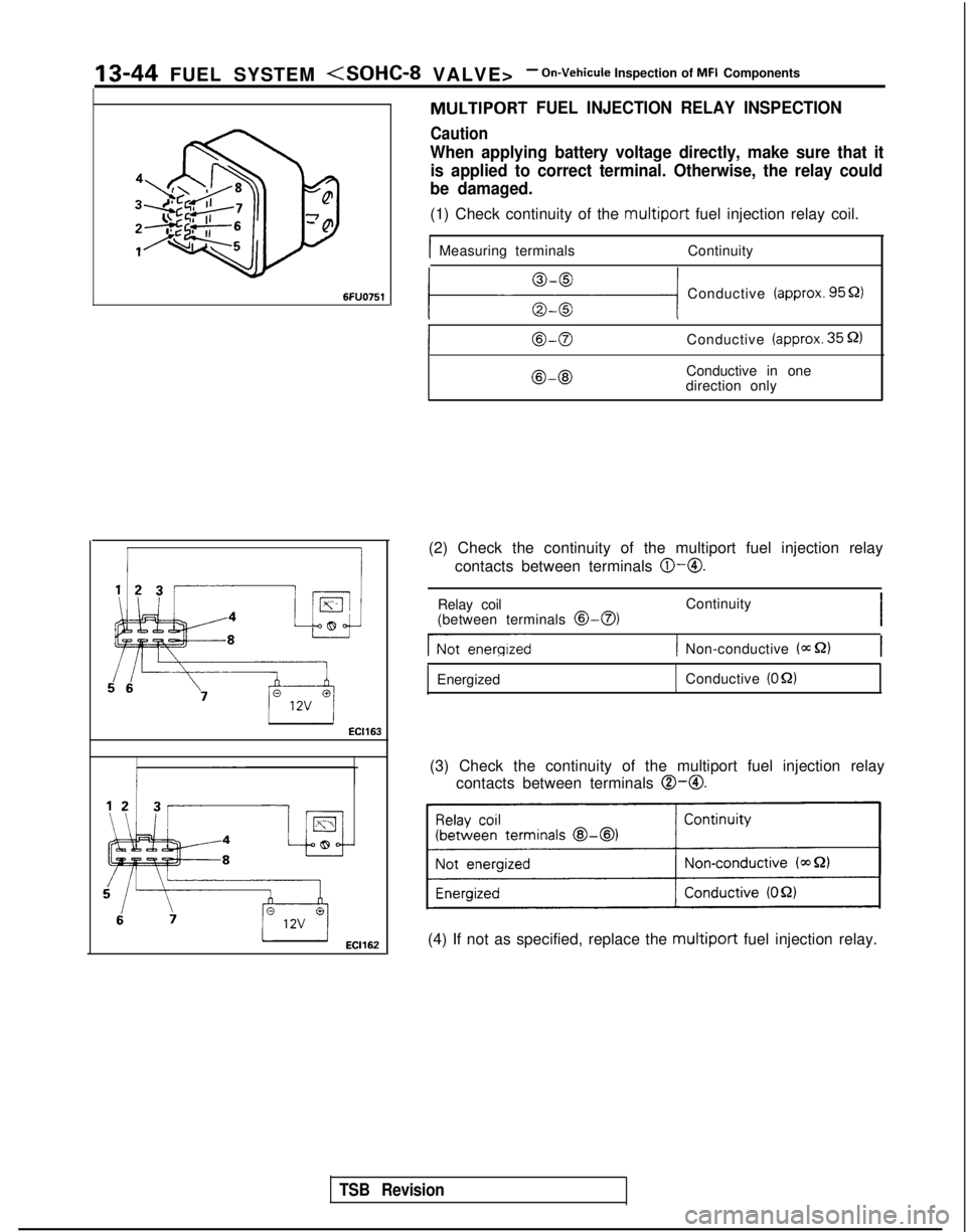
(1) Check continuity of the multiport fuel injection relay coil.
IMeasuring terminals Continuity
MULTIPORT FUEL INJECTION RELAY INSPECTION
Caution
111 Conductive (approx. 9551)
Conductive (approx. 35 52)
@-@IConductive in one
direction only
(2) Check the continuity of the multiport fuel injection relay contacts between terminals
@-@.
TSB Revision
Relay coil
(between terminals @>-a)Continuity
I
Gienergized1 Non-conductive (=S2)
Energized Conductive (OQ)
(3) Check the continuity of the multiport fuel injection relay
contacts between terminals
0-O.
(4) If not as specified, replace the multiport fuel injection relay.
Page 188 of 1273
13-46 FUEL SYSTEM
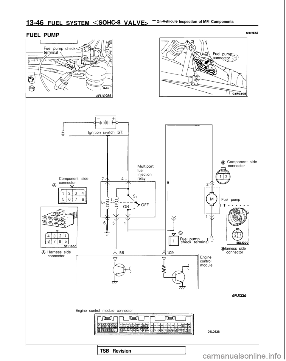
FUEL PUMP
MlBYEAB
@ Component side connector
-
\
1Fuel pump M
$
1
I
-
Multiportfuel
injection
relay
Component side
7/-/
L2 :<
\
6’
_!
4,
@connector,
I-~ i1SlLl”’-------.,\OFF I OIL
,’e-
\/ \/1\/ \/5 1 2
’
-
I
IT-----
-
1!
check terminal -5EL1200j
Engine
control module @ Harness side
connector
@ Harness side
connector
I
6FU1236
Engine control module connector OlLO838
TSB RevisionI
Page 189 of 1273
FUEL SYSTEM
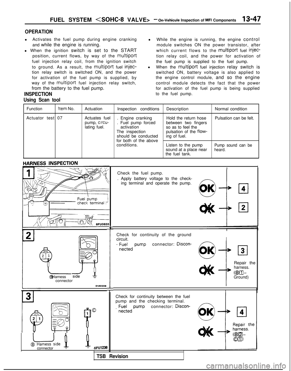
OPERATION
l
Activates the fuel pump during engine cranking
and while the engine is running.
l When the ignition switch is set to the START
position, current flows, by way of the
multiport
fuel injection relay coil, from the ignition switch
to ground. As a result, the
multiport fuel injec-
tion relay switch is switched ON, and the power
for activation of the fuel pump is supplied, by
way of the
multiport fuel injection relay switch,
from the battery to the fuel pump.
INSPECTION
Using Scan tool
l While the engine is running, the engine control
module switches ON the power transistor, after
which current flows to the
multiport fuel injec-
tion relay coil, and the power for activation of
the fuel pump is supplied to the fuel pump.
l When the
multiport fuel injection relay switch is
switched ON, battery voltage is also applied to
the engine control module, and so the engine
control module detects the fact that the power
for activation of the fuel pump is being supplied
to the fuel pump.
Function Item
No.
Actuation Inspection conditions DescriptionNormal condition
Actuator test 07 Actuates fuel
. Engine cranking Hold the return hosePulsation can be felt.
pump, clrcu-
. Fuel pump forced between two fingers
lating fuel. activation
so as to feel the
The inspection pulsation of the
flow-should be conducteding of fuel.
for both of the above conditions. Listen to the pump
Pump sound can besound at a place nearheard.the fuel tank.
Check for continuity of the ground
circuit.
I
. ;E;;,, pumpconnector: Discon-
2
1
Y-
!
Repair theharness.
@El- @ HarnessGround)connector
O~AOZOl3
I
Check for continuity between the fuel
pump and the checking terminal.
connector: Discon-
1
@uide 1
B
0. ;;;;,,
pump
L
Check the fuel pump.
. Apply battery voltage to the check-
ing terminal and operate the pump.
!I:7
OK
connector :1 = 6FUl238
TSB Revision
Page 198 of 1273
13-56 FUEL SYSTEM
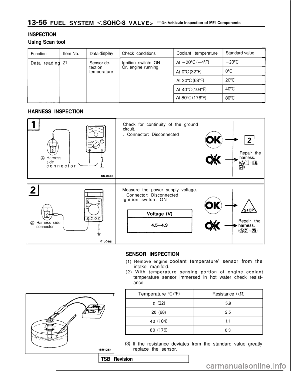
INSPECTION
Using Scan tool
FunctionItem No.
Data reading
-*LI
Data display
Sensor de-
tection
temperature
HARNESS INSPECTION
connector OlLO461Check conditions
Ignition switch: ON
Or, engine running Coolant temperature
Standard value
At
-20°C (-4°F)-20°C
At 0°C (32°F)0°C I
At
20°C (68°F)20°C
connector - Ic
OIL0463L
-16R1251
Temperature “C (“F)Resistance (kS2)
0 (32)5.9
20 (68)2.5
40 (104)1.1
80 (176) 0.3
(3) If the resistance deviates from the standard value greatly
replace the sensor.
J
TSB Revision
At 40°C (104°F)40°C
At 80°C (176°F)80°C
1
Check for continuity of the ground
circuit.
. Connector: Disconnected
Repair the
harness.
b&XII-@.
lm
Measure the power supply voltage.I. Connector: Disconnected
Ignition switch: ONVoltage
(VI
SENSOR INSPECTION
(1) Remove engine coolant temperature’ sensor from the
intake manifold.
(2) With temperature sensing portion of engine coolan
t
temperature sensor immersed in hot water check resist-
ance.
Page 216 of 1273
13-74 FUEL SYSTEM
Hint 4:
If idling is possible even though the crankshaft posi-
tion sensor indicated rpm is a deviation from the standard value, the cause is usually a malfunction of
something other than the crankshaft position sen-
sor.
Examples:
(1) Malfunction of the coolant-temperature sensor.
(2) Malfunction of the idling-speed control motor.
(3) Improper adjustment of the standard idling
speed.
INSPECTION
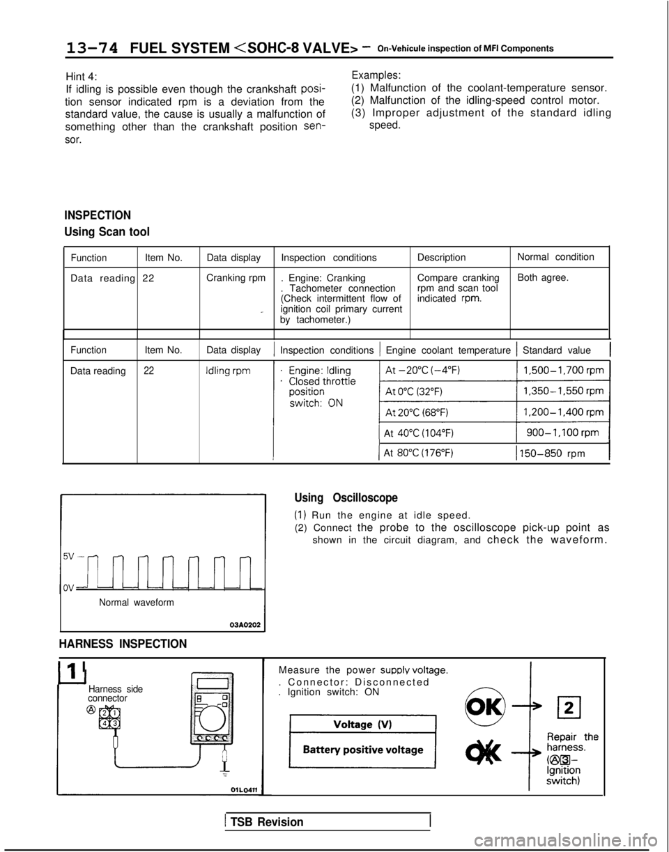
Using Scan tool
FunctionItem No.
Data reading 22 Data display
Inspection conditions DescriptionNormal condition
Cranking rpm . Engine: Cranking Compare crankingBoth agree.
. Tachometer connection rpm and scan tool
(Check intermittent flow of indicated
rpm._ignition coil primary current
by tachometer.)
Function
Data reading Item No.22
Data display1 Inspection conditions 1 Engine coolant temperature 1 Standard value1
1 At 40°C (104°F)1 900-1,100rpm 1
III-I( At 80°C (176°F)1 150-850 rpm
Normal waveform
03AO202
HARNESS INSPECTION
Ilr I
Using Oscilloscope
(1) Run the engine at idle speed.
(2) Connect the probe to the oscilloscope pick-up point as
shown in the circuit diagram, and check the waveform.
Harness side
connector
@
Measure the power SUPPIY voltaoe.
. Connector: Disconnected
-. Ignition switch: ON
1 TSB Revision
Page 224 of 1273
13-82 FUEL SYSTEM
OPERATION
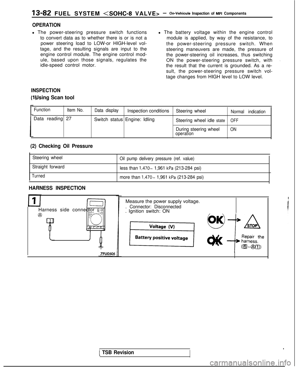
l The power-steering pressure switch functions
to convert data as to whether there is or is not apower steering load to LOW-or HIGH-level vol-
tage, and the resulting signals are input to the engine control module. The engine control mod-
ule, based upon those signals, regulates the
idle-speed control motor. l The battery voltage within the engine control
module is applied, by way of the resistance, to
the power-steering pressure switch. When
steering maneuvers are made, the pressure of
the power-steering oil increases, thus switching
ON the power-steering pressure switch, with
the result that the current is grounded. As a re-
sult, the power-steering pressure switch vol-
tage changes from HIGH level to LOW level.
INSPECTION I) Using Scan tool
Function
Item No.
Data reading 27
Data displayInspection conditions Steering wheelNormal indication
Switch status Engine: IdlingSteering wheel idle stateOFF
During steering wheelONoperation
(2) Checking Oil Pressure
Steering wheel
Straight forward
Turned
Oil pump delivery pressure (ref. value)
less than 1,470- 1,961 kPa (213-284 psi)
more than
1,470- 1,961 kPa (213-284 psi)
HARNESS INSPECTION
I-E-I
Harness side connector 6 0
@=- -0
Q
4 1
Measure the power supply voltage.
. Connector: Disconnected. Ignition switch: ON
[ TSB Revision
Page 232 of 1273
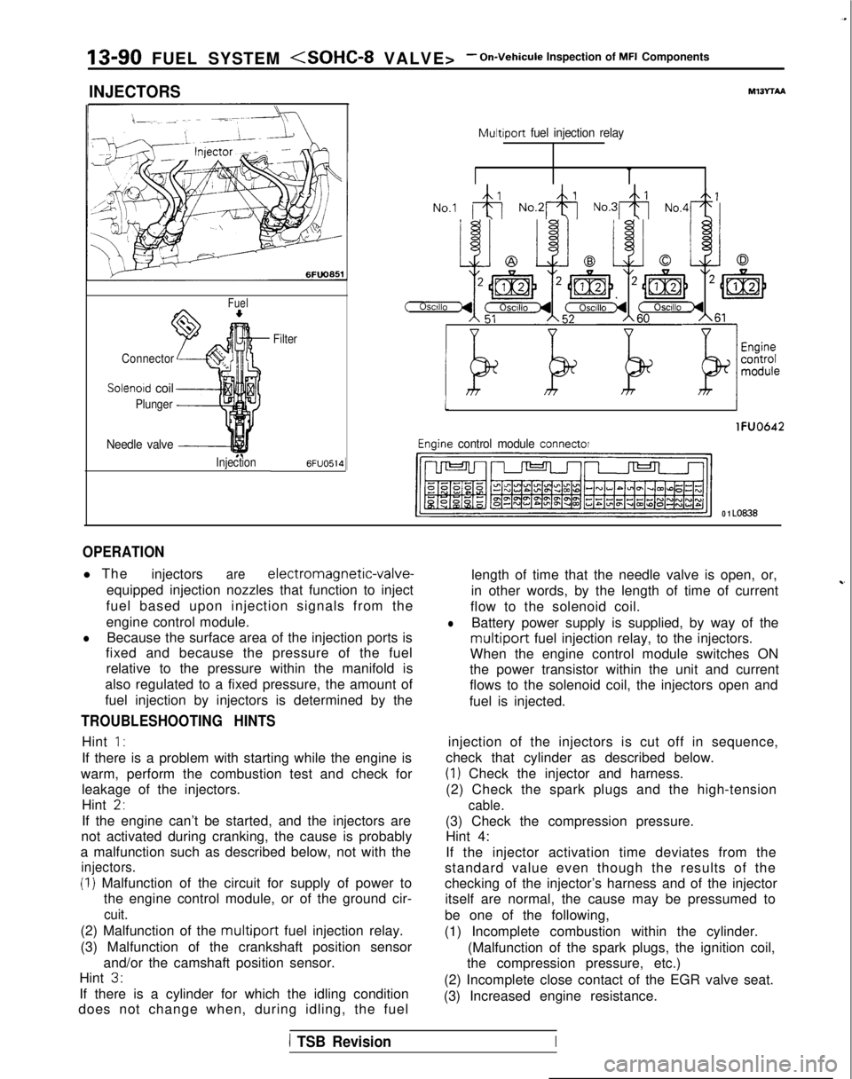
13-90 FUEL SYSTEM
INJECTORS
Fuel
Connector
Solenoid coil
Plunger
Needle valve -----I
InjectionFilter6FUO514
M13rrAA
Multiport
fuel injection relay
No.1 &j No.2& No.3& No,4+
tI
lFUO642
Engine control module connector
CJ=JW=U-I
0 1 LO636
OPERATION
l The
injectorsare electromagnetic-valve-
equipped injection nozzles that function to inject
fuel based upon injection signals from the
engine control module.
lBecause the surface area of the injection ports is
fixed and because the pressure of the fuel
relative to the pressure within the manifold is
also regulated to a fixed pressure, the amount of
fuel injection by injectors is determined by the
TROUBLESHOOTING HINTS
Hint 1:
If there is a problem with starting while the engine is
warm, perform the combustion test and check for leakage of the injectors.
Hint
2,
If the engine can’t be started, and the injectors are
not activated during cranking, the cause is probably
a malfunction such as described below, not with the
injectors.
(I) Malfunction of the circuit for supply of power to the engine control module, or of the ground cir-
cuit.
(2) Malfunction of the multiport fuel injection relay.
(3) Malfunction of the crankshaft position sensor and/or the camshaft position sensor.
Hint
3.
If there is a cylinder for which the idling condition
does not change when, during idling, the fuel length of time that the needle valve is open, or,
in other words, by the length of time of current
~-
flow to the solenoid coil.
lBattery power supply is supplied, by way of the
multiport fuel injection relay, to the injectors.
When the engine control module switches ON
the power transistor within the unit and current
flows to the solenoid coil, the injectors open and
fuel is injected.
injection of the injectors is cut off in sequence,
check that cylinder as described below.
(1) Check the injector and harness.
(2) Check the spark plugs and the high-tension
cable.
(3) Check the compression pressure. Hint 4:
If the injector activation time deviates from the
standard value even though the results of the
checking of the injector’s harness and of the injector itself are normal, the cause may be pressumed to
be one of the following,
(1) Incomplete combustion within the cylinder. (Malfunction of the spark plugs, the ignition coil,
the compression pressure, etc.)
(2) Incomplete close contact of the EGR valve seat.
(3) Increased engine resistance.
1 TSB RevisionI
Page 236 of 1273
13-94 FUEL SYSTEM
1
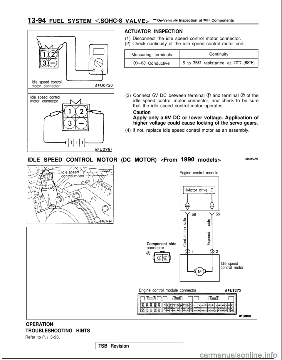
Idle speed control
motor connector
Idle speed control
motor connector6FUO750
6FUO9&
ACTUATOR INSPECTION
(1) Disconnect the idle speed control motor connector.
(2) Check continuity of the idle speed control motor coil.
Measuring terminals Continuity
0-0 Conductive
5 to 359 resistance at 20°C (68°F)
(3) Connect 6V DC between terminal @I and terminal @ of the
idle speed control motor connector, and check to be sure
that the idle speed control motor operates.
Caution
Apply only a 6V DC or lower voltage. Application of
higher voltage could cause locking of the servo gears.
(4) If not, replace idle speed control motor as an assembly.
IDLE SPEED CONTROL MOTOR (DC MOTOR)
Component sideconnector
@
43m00
Engine control module
77V s
.-:
z'Zc
EE
sI2
21<\2
Idle speedcontrol motor
MlOYUAG
Engine control module connector
6FU1275
OPERATION
TROUBLESHOOTING HINTS
Refer to P. ? 3-93.
TSB Revision