relay MITSUBISHI GALANT 1989 Service Owner's Guide
[x] Cancel search | Manufacturer: MITSUBISHI, Model Year: 1989, Model line: GALANT, Model: MITSUBISHI GALANT 1989Pages: 1273, PDF Size: 37.62 MB
Page 272 of 1273
13-130FUEL SYSTEM
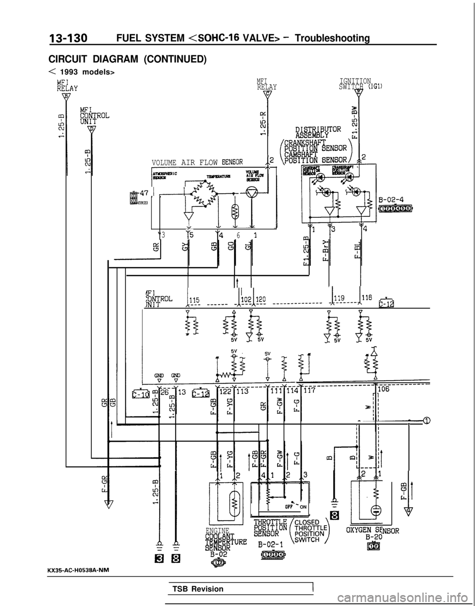
CIRCUIT DIAGRAM (CONTINUED)
< 1993 models>
VOLUME
A-47 1 &- -%--t
MFIRELAY IGNITIONSWITCH (IGl)
AIR FLOW EXNSOR,,2,\VCLLW7nwmAm
m 468 1ES 1
“375y461
1I
It II I
HFLb!. _-____ JLk? ______________ -bdl8 tQj
bui kk
B-02-4
m
0 .sT--q--
0
OF;- ONL
25
rl
I
1
G
ENGINE
#k&@"RE
:NSOR
KX35AC-H0538A-NM
TSB Revision
I
Page 281 of 1273
FUEL SYSTEM
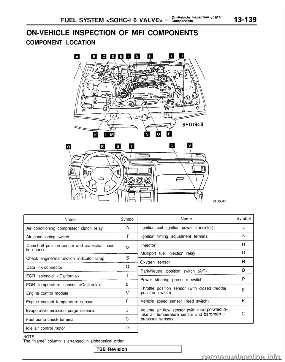
ON-VEHICLE INSPECTION OF MFI COMPONENTS
COMPONENT LOCATION
6FUO843
Name Symbol NameSymbol
Air conditioning compressor clutch relay A
Ignition coil (ignition power transistor)
L
Air conditioning switchTIgnition timing adjustment terminalK
Camshaft position sensor and crankshaft posi- InjectorHMtion sensor- Multiport fuel injection relayU
Check engine/malfunction indicator lampS- Oxygen sensorN
Data link connectorQ- Park/Neutral position switch (A/T)6
EGR solenoid
EGR temperature sensor
Throttle position sensor (with closed throttle
position switch)
EEngine control modulev
Engine coolant temperature sensorFVehicle speed sensor (reed switch)R
Evaporative emission purge solenoidJVolume air flow sensor (with incorporated,in-
take air temperature sensor and barometncC
Fuel pump check terminalGpressure sensor)
Idle air control motor
D
NOTEThe “Name” column is arranged in alphabetical order. TSB Revision
Page 285 of 1273
On-Vehicle Inspection of MFIFUEL SYSTEM
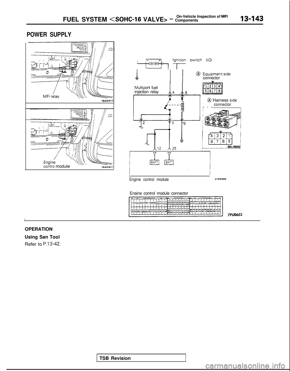
POWER SUPPLY
16AO411
contra module ,
;;lii’l’l’lb Ig;lon switch (IG)
MultIport
fuel
injection relay
/\4 /t\8
"
2
't'3 "6rt4,
Equipment sideconnector
@ Harness side
connector
--
-
Engine control module01105.4
Enaine control module connector
7FlJO653
I
OPERATION
Using San Tool Refer to
P.13-42.
TSB Revision
Page 286 of 1273
On-Vehicle Inspection of MFI
13-144FUEL SYSTEM
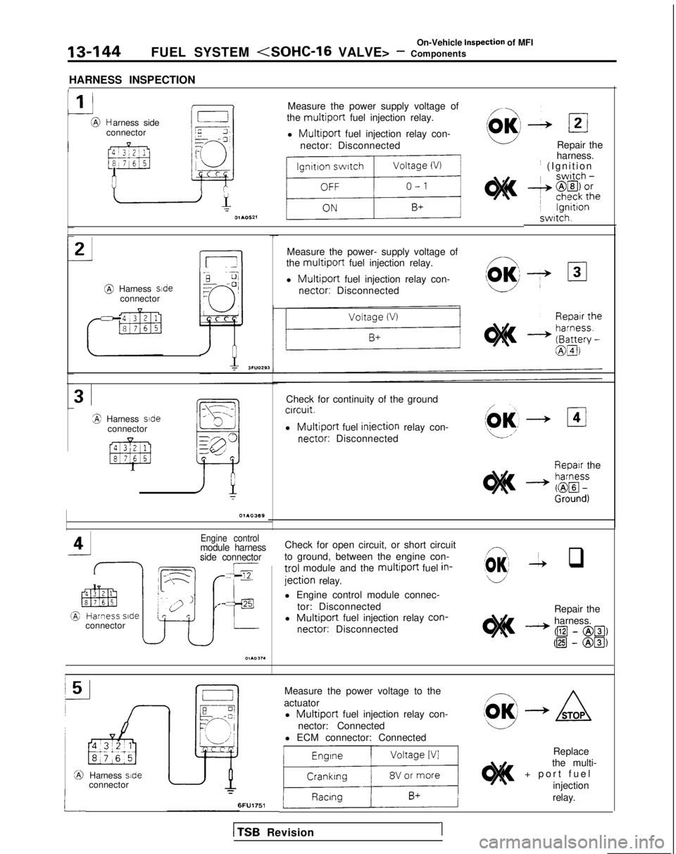
HARNESS INSPECTION
1
1 IMeasure the power supply voltage of
the
multiport fuel injection relay.
l
Multiport fuel injection relay con-
nector: Disconnected
r,
L
NC;Jr=--cl7
I
?-i3I+- c
-@ Harness side
connector
Repair the
harness. ~
(Ignition swrtch.
_J2
L5-l
Measure the power- supply voltage of
the
multiport fuel injection relay.
l
Multiport fuel injection relay con- nectar:
Disconnected @
Harness sdeconnector
3iCheck for continuity of the groundcrrcuit.
l Multiport fuel iniection
relay con- nectar:
Disconnected3 Harness side
connector
Repair theI
M.- zf$
Engine controlmodule harness
side connectorCheck for open circuit, or short circuit
to ground, between the engine con-
trol module and the multiport fuel in-
jection relay.
(03 -2 q
l Engine control module connec-
tor: Disconnected
l
Multiport fuel injection relay con-
nectar:
Disconnected Repair the
harness.
- @I
- @El, @I
- @Ia
connector
Measure the power voltage to the
actuator l
Multiport fuel injection relay con-
nector: Connected
l ECM connector: Connected
1li
Replace
the multi-
+ port fue
l
injection
Harness side
connector
relay.6FU1751
1
TSB
Revision1
Page 287 of 1273
‘On-Vehicle Inspection of MFIFUEL SYSTEM (SOHC-16 VALVE> - Components13-145
9FUOOlO
9FUOO18
1
TSB RevisionI
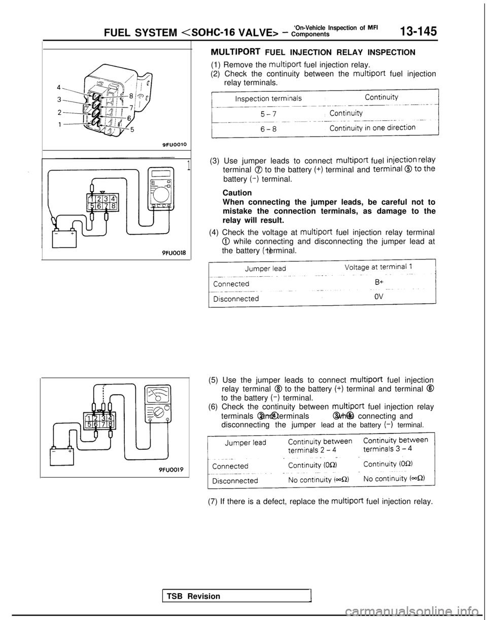
MULTIPORT FUEL INJECTION RELAY INSPECTION
(1) Remove the multiport
fuel injection relay.
(2) Check the continuity between the multiport
fuel injection
relay terminals.
(3) Use jumper leads to connect multiport
fuel
injection relay
terminal 0 to the battery (+) terminal and terminal 0 to the
battery (-)
terminal.
Caution
When connecting the jumper leads, be careful not to mistake the connection terminals, as damage to the
relay will result.
(4) Check the voltage at multiport
fuel injection relay terminal
@I while connecting and disconnecting the jumper lead at
the battery (-) terminal.
(5) Use the jumper leads to connect multiport
fuel injection
relay terminal
@I to the battery (+) terminal and terminal @
to the battery (-)
terminal.
(6) Check the continuity between multiport
fuel injection relay
terminals @-@I and terminals @-@I while connecting and
disconnecting the jumper lead at the battery
(-) terminal.
9FUOOl9
(7) If there is a defect, replace the multiport
fuel injection relay.
Page 289 of 1273
FUEL SYSTEM (SOHC-16 VALVE> - :::;::tt?ction Of MF’13-147
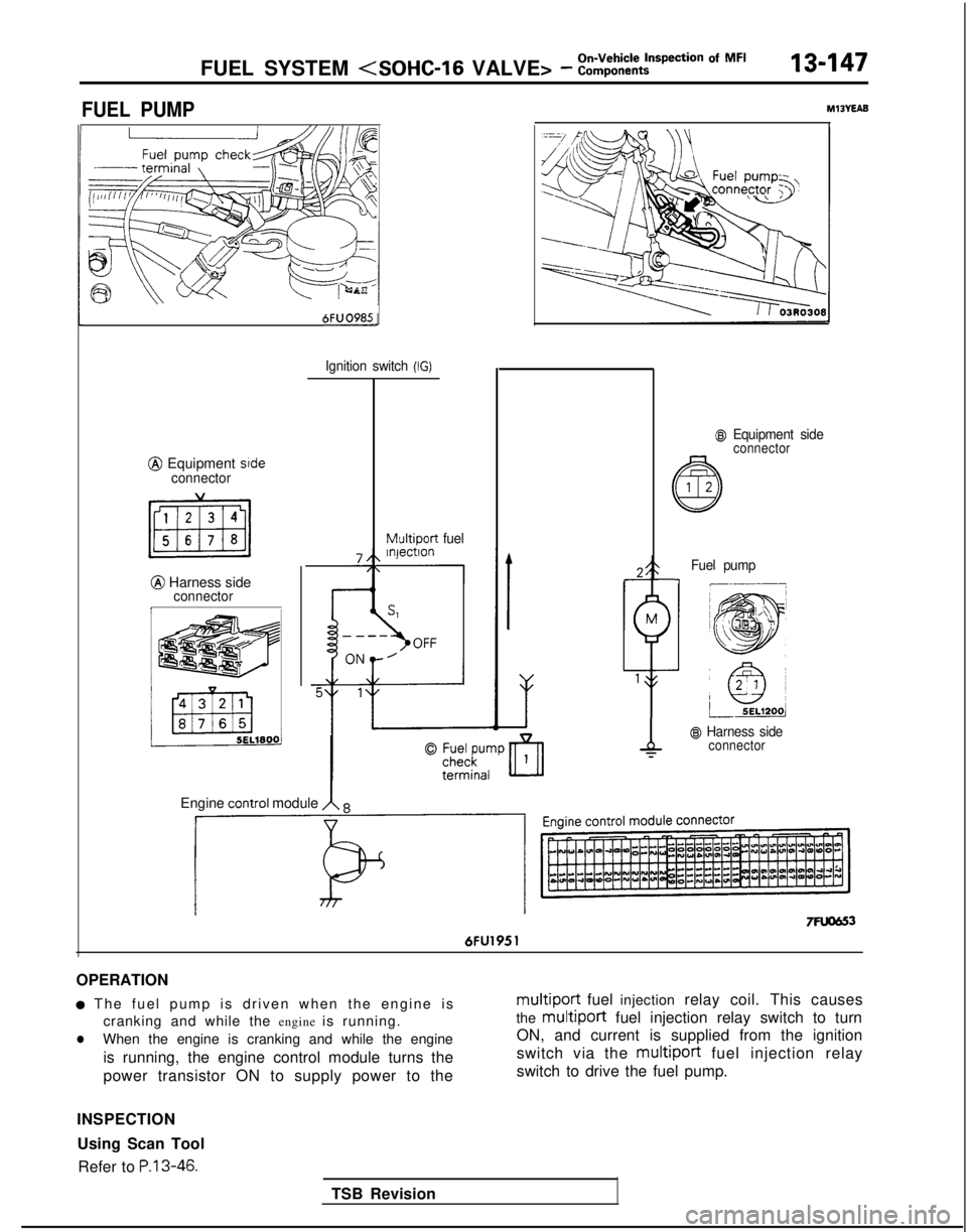
FUEL PUMPM13YEAB
6FUO985-
@ Equipment srdeconnector
@ Harness sideconnectorI
Ignition switch (IG)
Multiport
fuel
@I Equipment sideconnector
TSB Revision
Fuel pump-I
@ Harness sideconnector
Engine COntrOl module A 8
7Fuom 6FU1951
OPERATION
a The fuel pump is driven when the engine i
s
cranking and while the engine is running.
lWhen the engine is cranking and while the engine
is running, the engine control module turns the
power transistor ON to supply power to the
multiport fuel injection relay coil. This causes
the
multiport fuel injection relay switch to turn
ON, and current is supplied from the ignition
switch via the multiport
fuel injection relay
switch to drive the fuel pump.
INSPECTION Using Scan Tool Refer to
P.13-46.
Page 290 of 1273
On-Vehicle Inspection of MFI
13-148FUEL SYSTEM (SOHC-16 VALVE> - Components
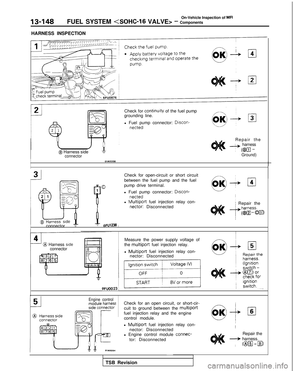
HARNESS INSPECTION
@ Harness sideconnector
Check for continuity of the fuel pump
grounding line.
l Fuel pump connector: Discon-
netted
Repair th
e
4 harness
~
@El-Ground)
Check for open-circuit or short circuit
between the fuel pump and the fuel
pump drive terminal.
l Fuel pump connector:
Drscon-
nettedl Multiport fuel injection relay con- nectar:
Disconnected
I/
2 .lr/ Repair theL^Srr,-..-r
P
9vh
connector T-y 6FU1238!
I
@ Harness srdeconnector
Measure the power supply voltage of
the
multiport fuel injection relay.
l
Multiport fuel injection relay con-
nector: Disconnected
r
9FUOO23;
IIIEngine controlCheck for an open circuit, or short-cir-
cuit to ground between the
multiport
fuel injection relay and the enginecontrol module.
l
Multiport fuel injection relay con-
nector: Disconnected
l Engine control module connec-
tor: Disconnected!
Repair the
+ harness. ~
@H-B)
TSB Revision
Page 291 of 1273
On-Vehicle Inspection of MFIFUEL SYSTEM
a Harness side
connector
--------
m
J-----k
N
qp
CI
F
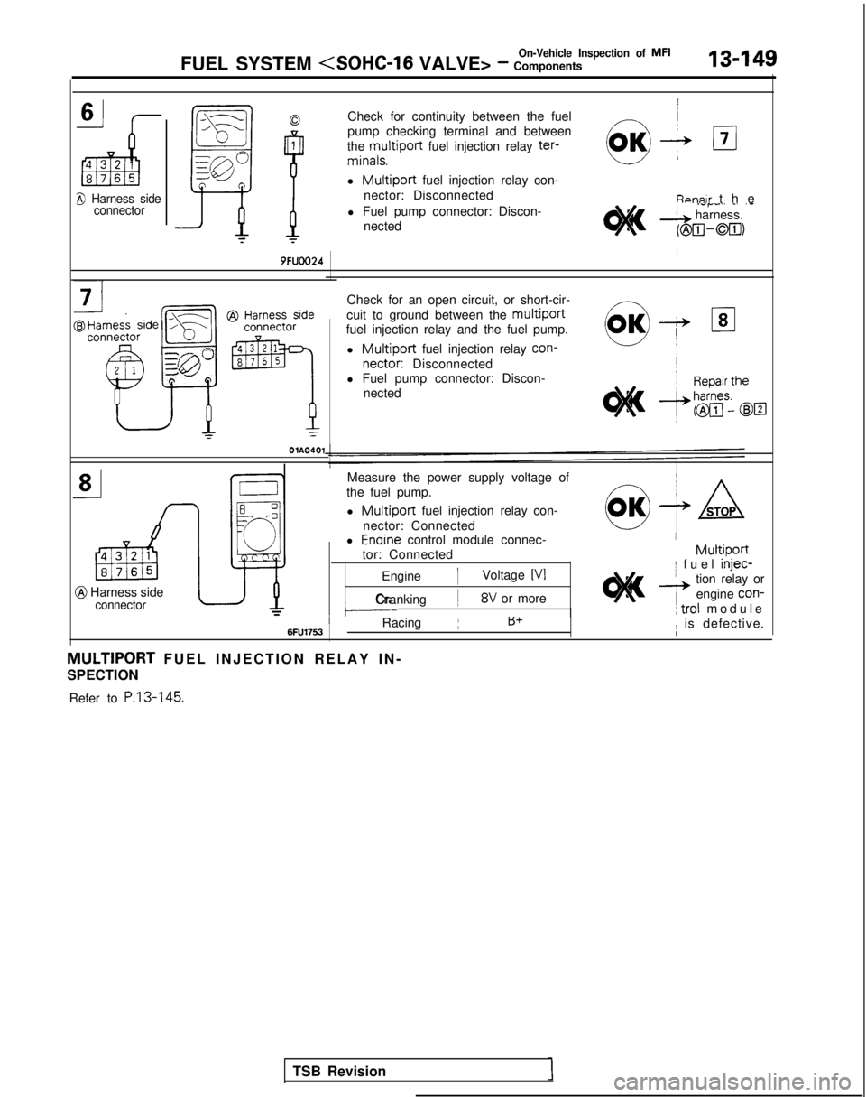
Check for continuity between the fuel
pump checking terminal and between
the
multiport fuel injection relay ter- minals.
l
Multiport fuel injection relay con-
nector: Disconnected Fipnn~r
the
l Fuel pump connector: Discon-
nected
.-P-” _’ ‘-& harness.
(@m-00,
I9FUOO24
OlA0401
Check for an open circuit, or short-cir-
cuit to ground between the
multiport
fuel injection relay and the fuel pump.
l
Multiport fuel injection relay con-
nectar:
Disconnected
l Fuel pump connector: Discon-
nected
@ Harness sideconnector
Measure the power supply voltage of
the fuel pump.
l
Multiport fuel injection relay con-
nector: Connected
l
Enoine control module connec-
tor: Connected
Engine
1Voltage IV1
cCranking ~8V or more-
I
MultiportI fuel injec-
__, tion relay or
1
engine con-
~
trol
module
TSB Revision
IRacing Iid+: is defective.6FU175.3I
MULTIPORT FUEL INJECTION RELAY IN
-
SPECTION
Refer to P.13-145.
Page 292 of 1273
On-Vehicle Inspection of MFI
13450FUEL SYSTEM
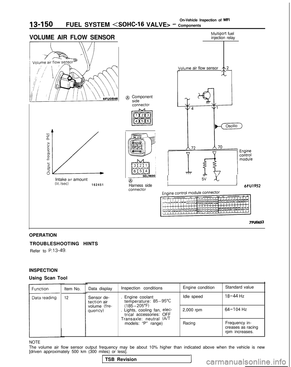
VOLUME AIR FLOW SENSOR
Intake air amountWsec)16245
1
@ Componentsideconnectof
Multiport
fuel
injection relay
/ohme air flow sensor/\2/\-
@Harness side
Isv xI 6FU1952
OPERATION TROUBLESHOOTING HINTSRefer to
P.13-49.
INSPECTION
Using Scan Tool
Item No.
12
Data displayInspection conditions Engine condition
Standard value
Sensor de- . Engine coolant Idle speed
18-44 Hz
tection airtemperature: 85-95°C
volume (fre- (185-205°F)
quency)
. Lights, cooling fan, elec-
2,000 rpm64-l 04 Hz tricaI
accessories: OFF
Transaxle: neutral
(PJTmodels: “P” range)RacingFrequency in-
creases as racing rpm increases.
NOTE
The volume air flow sensor output frequency may be about 10% higher than\
indicated above when the vehicle is new[driven approximately 500 km (300 miles) or less].
TSB Revision
1
Page 293 of 1273
On-Vehicle Inspection of MFIFUEL SYSTEM
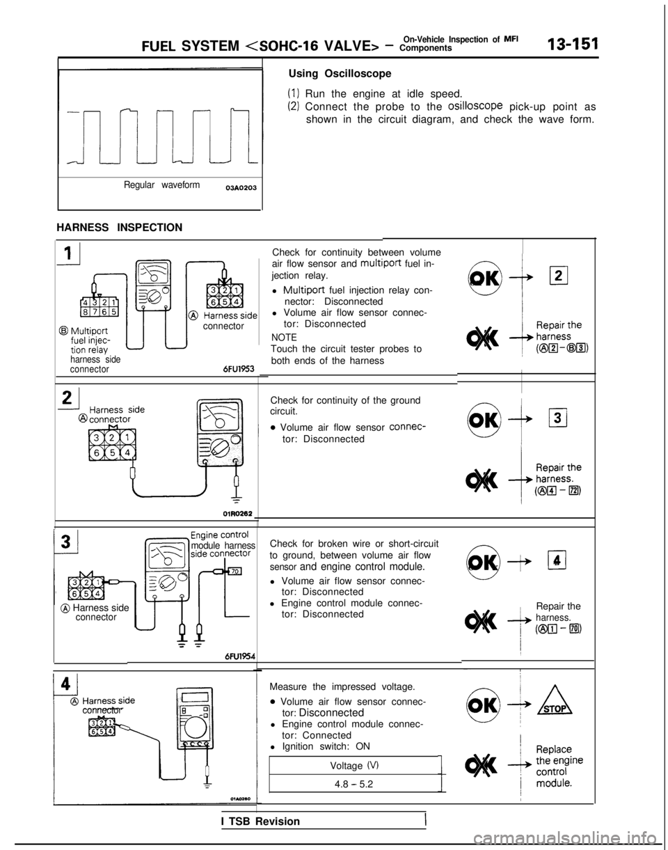
Using Oscilloscope
(1) Run the engine at idle speed.
(2) Connect the probe to the osilloscope
pick-up point as
shown in the circuit diagram, and check the wave form.
Regular waveform03AO203
HARNESS INSPECTION
Check for continuity between volume
air flow sensor and
multiport fuel in-
jection relay.
l
Multiport fuel injection relay con-
nector: Disconnected
l Volume air flow sensor connec-
tor: Disconnected
NOTE
Touch the circuit tester probes to
both ends of the harness
a+
OK 121
harness side
connector6FU1953
connector
Check for continuity of the ground-Icircuit.
0 Volume air flow sensor connec-WI+ 131tor: DisconnectedL-l I
OlR0262
/I
module harness
@ Harness sideconnector
= =
6FU1954
0O
K
-I+
Check for broken wire or short-circuit
to ground, between volume air flow
sensor and engine control module.
l Volume air flow sensor connec- tor: Disconnected
l Engine control module connec- tor: Disconnected
El4
Repair the
harness.
(ml-El)
Measure the impressed voltage.
0 Volume air flow sensor connec- tor: Disconnected
l Engine control module connec-
tor: Connected
l Ignition switch: ONconnector
Voltage (V)
4.8 - 5.2
I TSB Revision