relay MITSUBISHI GALANT 1989 Service Service Manual
[x] Cancel search | Manufacturer: MITSUBISHI, Model Year: 1989, Model line: GALANT, Model: MITSUBISHI GALANT 1989Pages: 1273, PDF Size: 37.62 MB
Page 318 of 1273
13-176FUEL SYSTEM
1
@ Harnesssrde connector
7FUOSO5
Measure the impressed voltage./\1A
l Power steering pressure switch
connector: Disconnected
l Engine control module connec-
tor: Connected
l Ignition switch: ON
Voltage
04
1 modul
e
J
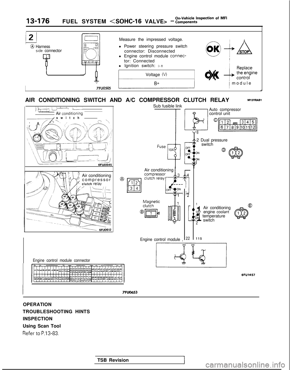
AIR CONDITIONING SWITCH AND A/C COMPRESSOR CLUTCH RELAY
hl13YRABl
ii++----- ,L’AI:
Air conditionino1 switch -
‘A //A\‘A /,,--.l, ,+q‘\
\\Wj i EYAJ26FUO645
Air conditioning
compresso
r
clutch
relav
~-1 6FUO612
Engine control module connector
Sub fusible link
TSB Revision Air conditioning
1
@ m i”“:F$
1
Engine control module ,
I7FUO653
-
,4,
g:2
[
22
Auto compressorcontrol unit
6
2 Dual pressure
I switch 3N
3N
1
1
Air conditioningOFFengine COOlant,^N temperature
2switch
11
5
6FU145.7
OPERATION
TROUBLESHOOTING HINTS INSPECTION
Using Scan Tool Refer
to P.13-83.
Page 323 of 1273
FUEL SYSTEM
Of MF’13-181
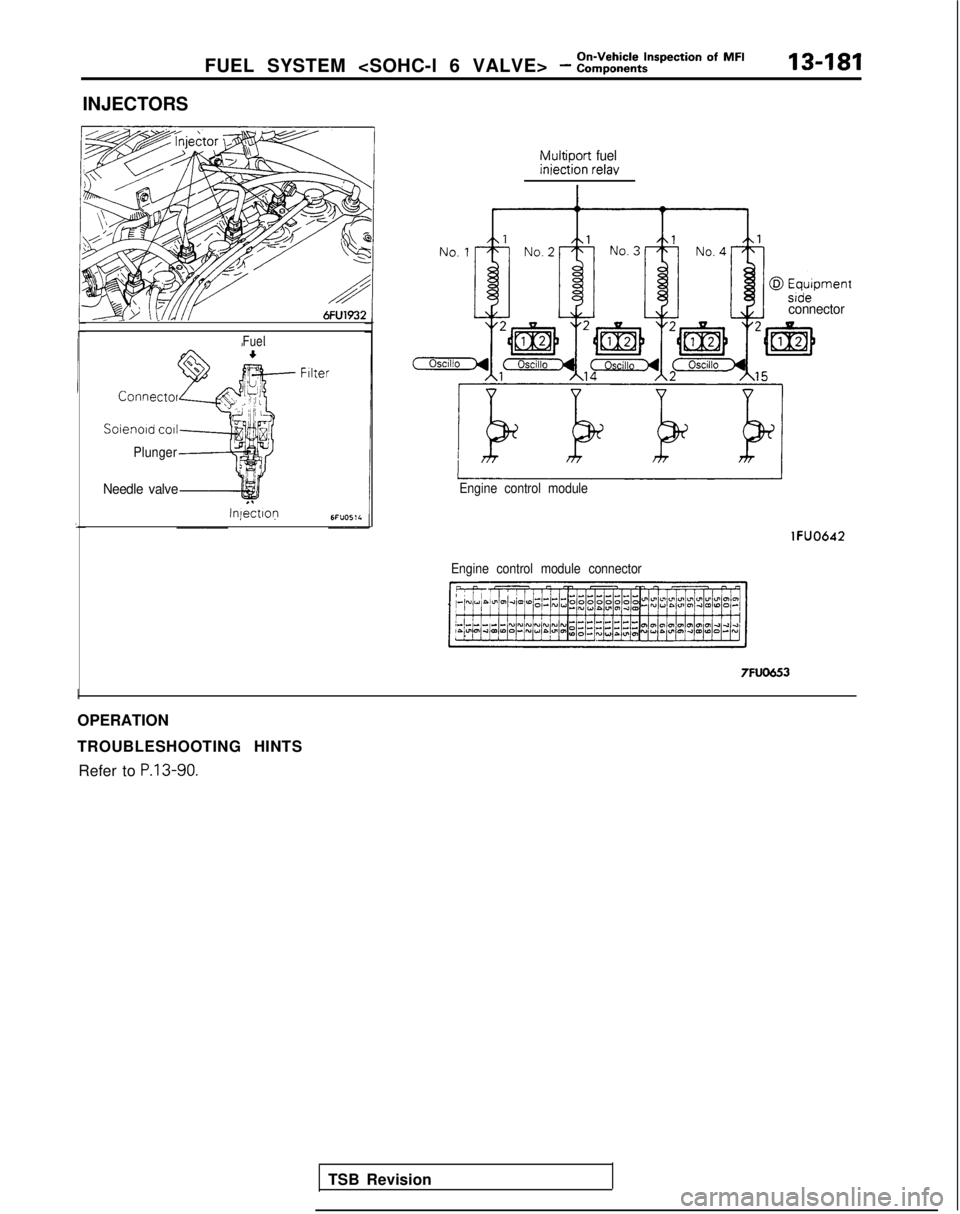
INJECTORS
Fuel
Connect01
Soienold co11
Plunger
Needle valve
Injectlop
Multiport fueliniection relay
TSB Revision
connector
Engine control module
Engine control module connector
lFUO642 7FUO653
I
OPERATION
TROUBLESHOOTING HINTS
Refer to
P.13-90.
Page 325 of 1273

FUEL SYSTEM
HARNESS INSPECTION
@ Multiport fuelinjection relayharness side
connector
,\---L
Ell---l0
!I?
pJ”
D
Harness
side
connector
6FU1779
@@@03Harness side
connector
1
Pmodule harness
side connector
=lFUO643
ACTUATOR INSPECTION
Refer to
P.13-92.
r I
I-
T
L
Check for continuity between injector
and
multiport fuel injection relay.
l lniector connector: Disconnected
l
tviultiport fuel injection relay con-
nector: Disconnected
NOTE
Touch the circuit tester probes to both
ends of the harness. Repair the
harnessCm
- 0@3,
Check for an open circuit, or a short
circuit to ground between the engine
control module and the injector.
l Engine control module connec-
tor: Disconnected
l Injector connector: Disconnected
TSB Revision
I
Page 331 of 1273
On-Vehicle Inspection of MFI
FUEL SYSTEM (SOHC-16 VALVE> - Components13-189
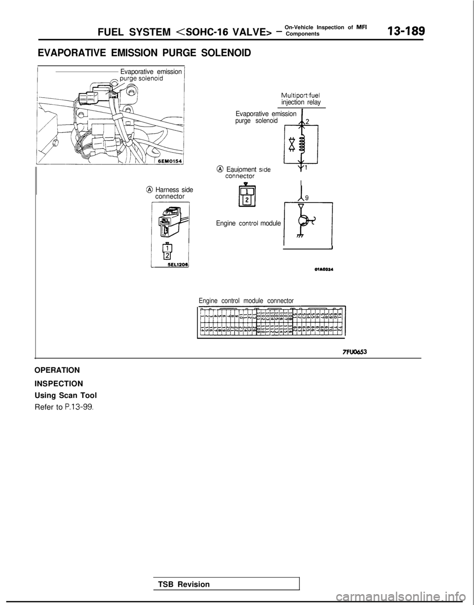
EVAPORATIVE EMISSION PURGE SOLENOID
IEvaporative emission/
Multipomfuel
injection relay
Evaporative emission
purge solenoid
-cofxiectorVI@ Harness side connector
p
Q I:
1
@ Eauioment side
Engine !!!I module ki
J
5ELl205)
TSB Revision
Engine control module connector
OPERATION
INSPECTION
Using Scan Tool
Refer to
P.13-99.
Page 332 of 1273
13-190
On-Vehicle Inspection of MFI
FUEL SYSTEM
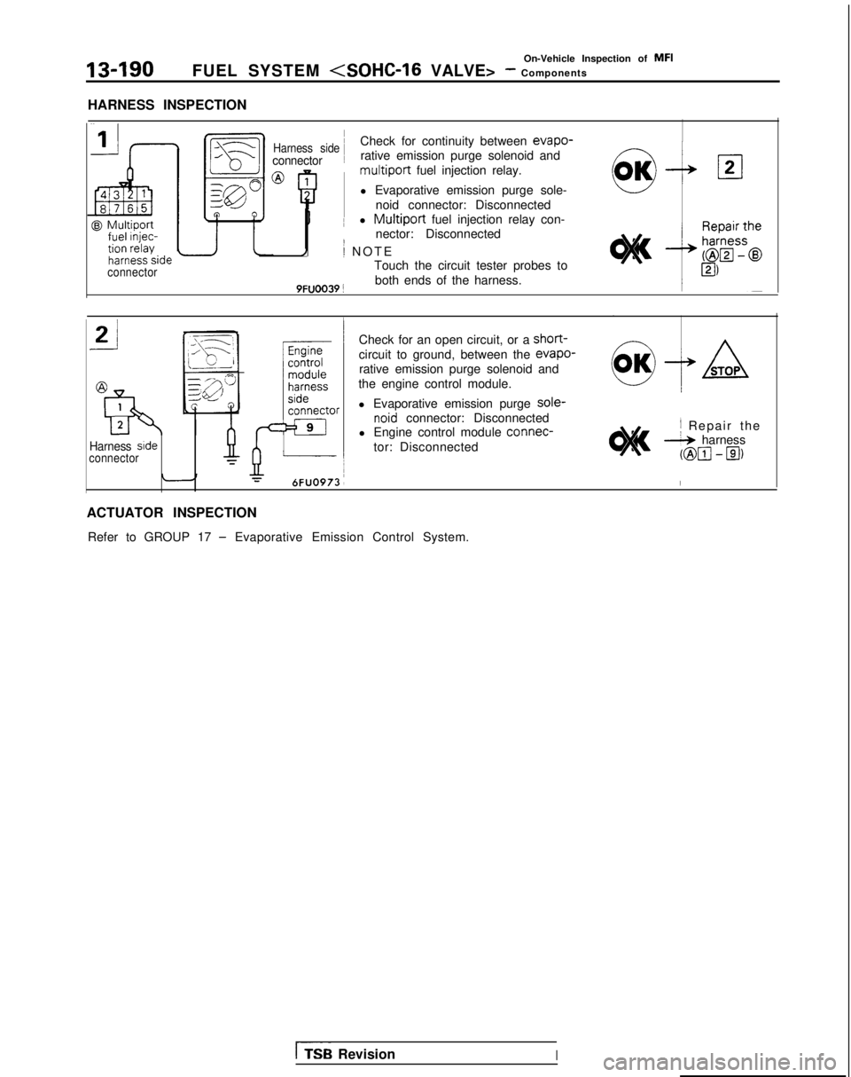
HARNESS INSPECTION
@ Multiport
connector ~
Harness sideCheck for continuity between evapo-
connector
~
rative emission purge solenoid andmultiport fuel injection relay.
l Evaporative emission purge sole- noid connector: Disconnected
I ~
l Multiport fuel injection relay con-
nector: Disconnected
1; NOT
E
Touch the circuit tester probes to
9FUOO39 !both ends of the harness.
Check for an open circuit, or a
short-
circuit to ground, between the evapo-
rative emission purge solenoid and
the engine control module.
Harness srdeconnector
l Evaporative emission purge sole-
noid connector: Disconnected
l Engine control module connec-
tor: Disconnected,I Repair th
e
* harness
@m-El)
I
ACTUATOR INSPECTION
Refer to GROUP 17
- Evaporative Emission Control System.
I%% RevisionI
Page 333 of 1273
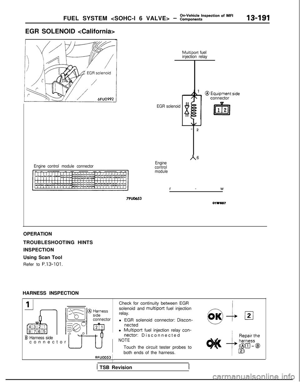
FUEL SYSTEM
EGR SOLENOID
I
Engine
control module connector
Multiport fuel
injection relay
EGR solenoid
connector
\/ ‘
“
2
A6Engine
control
module
r-
w
7FlJOU3OlWIS7
OPERATION
TROUBLESHOOTING HINTS
INSPECTION
Using Scan Tool
Refer to P.13-101.
HARNESS INSPECTION
_11
I IIF5
connector
@I Harness sideconnector ul[ J
9FUOO53
Check for continuity between EGR
solenoid and
multiport fuel injection-!relay.
l EGR solenoid connector: Discon-
nettedw
l Multiport fuel injection relay
con-I
nectar:
Disconnected
NOTE
Touch the circuit tester probes to
both ends of the harness. 1
MI,
1 TSB Revision
Page 334 of 1273
On-Vehicle Inspection of MFI13-192FUEL SYSTEM (SOHC-16 VALVE> - Components
connector
Engine control
module
harness
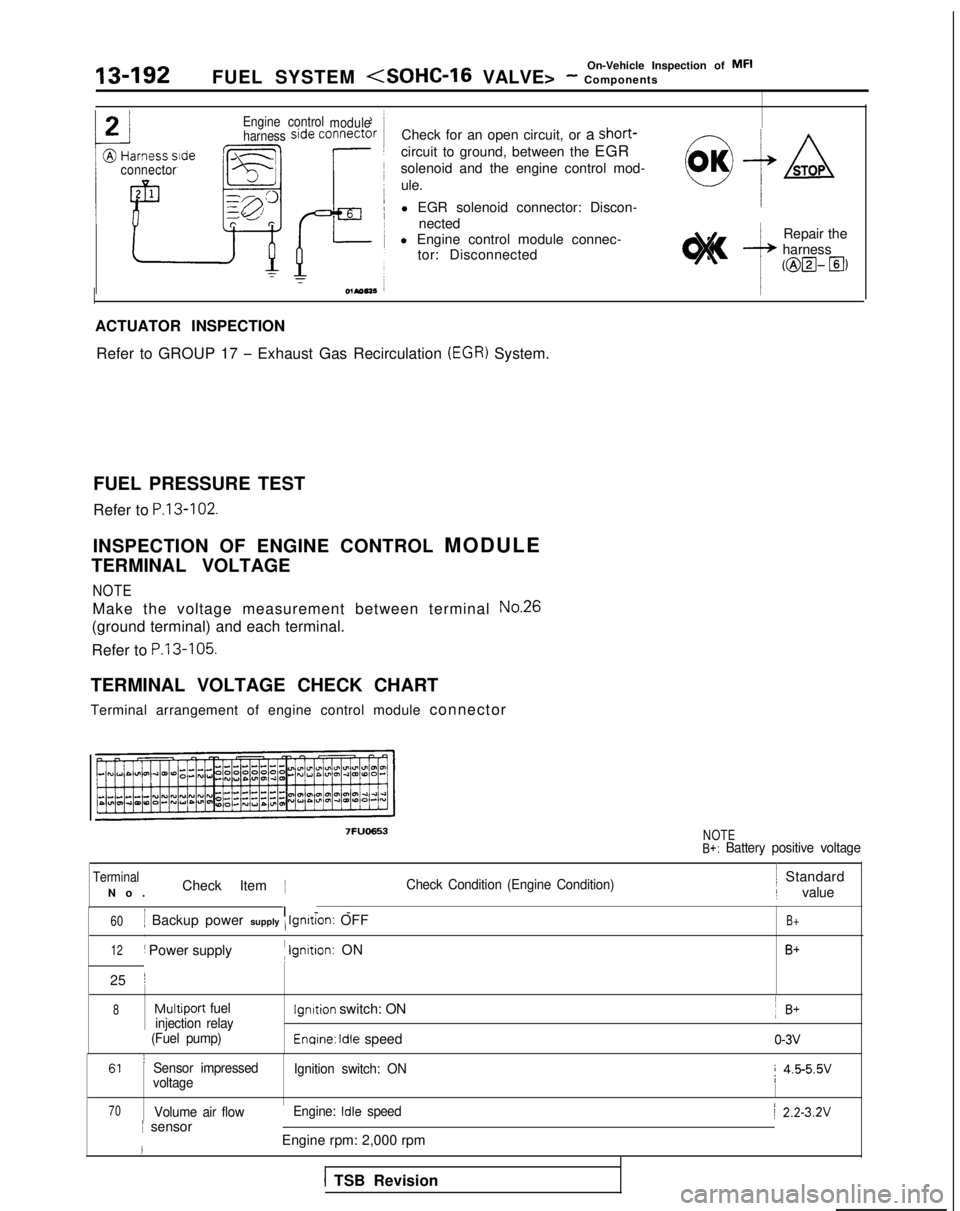
Check for an open circuit, or a short-
circuit to ground, between the EGR
solenoid and the engine control mod-
ule.
l EGR solenoid connector: Discon- nected
l Engine control module connec- tor: Disconnected
0OK+ASTOP
,
wsL
Repair the
harness
mzl- El)
ACTUATOR INSPECTION
Refer to GROUP 17
- Exhaust Gas Recirculation (EGR) System.
FUEL PRESSURE TEST
Refer to
P.13-102.
INSPECTION OF ENGINE CONTROL MODUL
E
TERMINAL VOLTAGE
NOTE
Make the voltage measurement between terminal No.26
(ground terminal) and each terminal.
Refer to
P.13-105.
TERMINAL VOLTAGE CHECK CHART
Terminal arrangement of engine control module connector
7FUQ653NOTEB+: Battery positive voltage
Terminal ~
No
.
Check Item ~
Check Condition (Engine Condition)/ Standard
/ value
60j Backup power supply i Ignrtron: OFF
I-
-
,
12/ Power supplyI Ignrtion: ON
25
j
B+
B+
8
Multiport fuellgnrtion switch: ON ~
B+injection relay~ (Fuel pump)Enqine: Idle speedo-3v
61 ’Sensor impressed
Ignition switch: ONi 4.5-5.5v
voltage
70Volume air flow Engine: Idle speed/ 2.2-3.2Vj sensor
IEngine rpm: 2,000 rpm
1 TSB Revision
Page 335 of 1273
FUEL SYSTEM
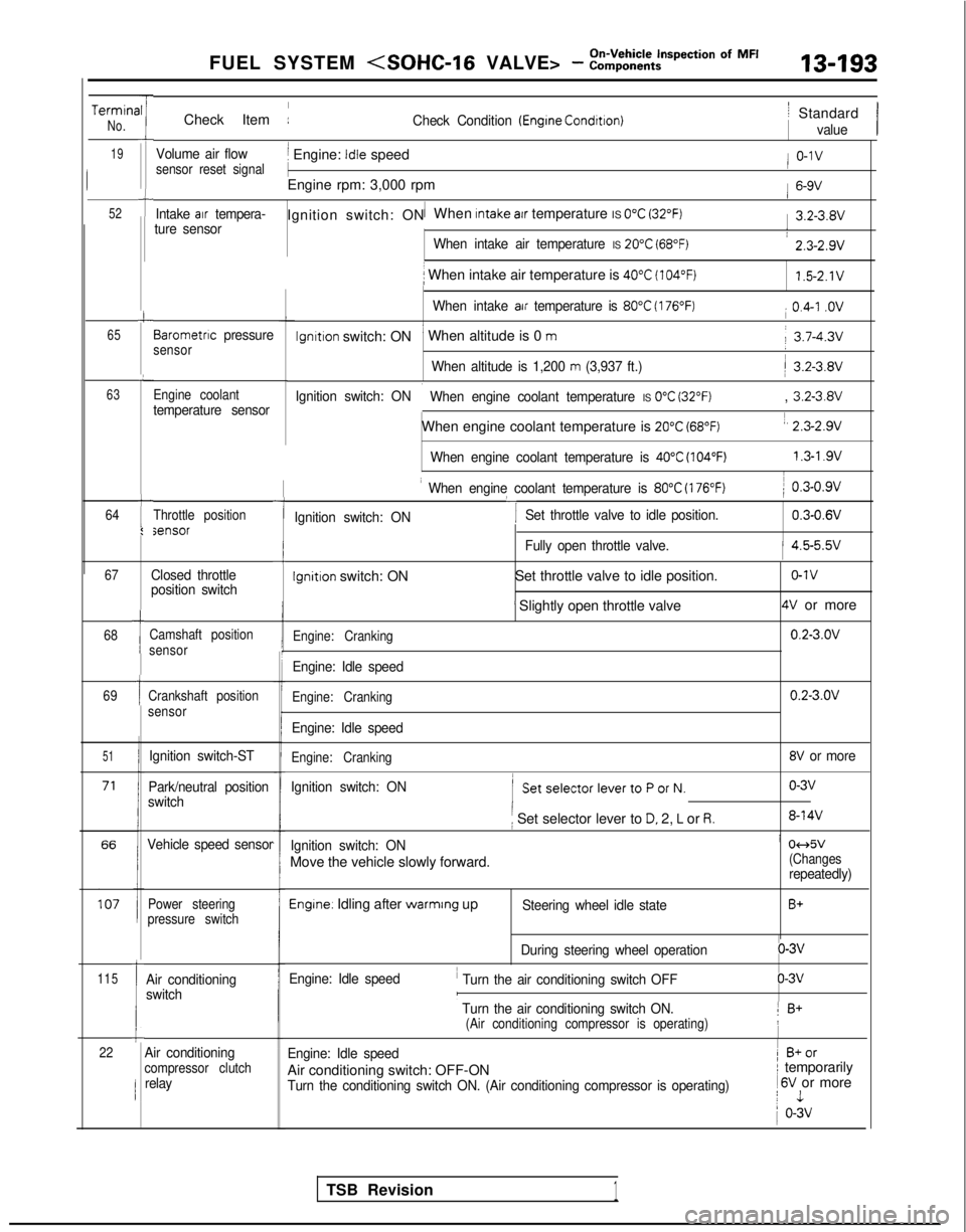
TerminaNo.
19
52
-rII
i
t
c
65
L
63
64t
I:
I
Check Item :Check Condition (Engrne Condrtron)
Volume air flowj Engine: Idle speedsensor reset signal
1
Engine rpm: 3,000 rpm
Intake air tempera-1Ignition switch: ON When Intake atr temperature IS 0°C (32°F)ture sensor
When intake air temperature IS 20°C (68°F)
i When intake air temperature is 40°C (104°F)
When intake air temperature is 80°C (176°F)
lgnltlon switch: ON’ When altitude is 0 m
When altitude is 1,200 m (3,937 ft.)
Ignition switch: ON
i When engine coolant temperature IS 0°C (32°F)
When engine coolant temperature is 20°C (68°F)
When engine coolant temperature is 40°C (104°F)
Barometnc pressuresensor
Engine coolant
temperature sensor
Throttle positionsensor
67
68
69
51
115
1
1
Ic22
Closed throttle
position switch
Camshaft position
sensor
Crankshaft position
sensor
Ignition switch-ST
Park/neutral position
switch
Vehicle speed sensor
Power steering
pressure switch
Air conditioning
switch
-I
I When engine coolant temperature is 80°C (176°F)
‘I
) 0.3-0.9v
Ignition switch: ON Set throttle valve to idle position.
0.3-0.6V
iFully open throttle valve.1 4.5-5.5v
Ignition switch: ON
Set throttle valve to idle position.o-1v
’ Slightly open throttle valve4V or more
Engine: Cranking0.2-3.OV
Engine: Idle speed
Engine: Cranking0.2-3.OV
Engine: Idle speed
Engine: Cranking8V or more
Ignition switch: ON
( SetselectorlevertoPorN.o-3v
i Set selector lever to D. 2, L or R.8-14V
Ignition switch: ONi 04d5v
Move the vehicle slowly forward.(Changesrepeatedly)
Engine. Idling after warmrng upSteering wheel idle stateB+
During steering wheel operationo-3v
Engine: Idle speed
’ Turn the air conditioning switch OFFo-3vI
’ Turn the air conditioning switch ON.1 B+(Air conditioning compressor is operating)!
Engine: Idle speed1 B+or
Air conditioning switch: OFF-ONI temporarily
Turn the conditioning switch ON. (Air conditioning compressor is operat\
ing) 1
6V or morej 1
1 o-3v
/ Standard
value
/ o-1v
1 6-9V
1 3.2-3.8V
: 2.3-2.9v
1.5-2.1V
i 0.4-I .ov
j 3.7-4.3v
/ 3.2-3.8V
, 3.2-3.8V
1, 2.3-2.9v
1.3-l .9vI
Air conditioningcompressor clutchrelay
TSB Revision1
Page 338 of 1273
13-196FUEL SYSTEM
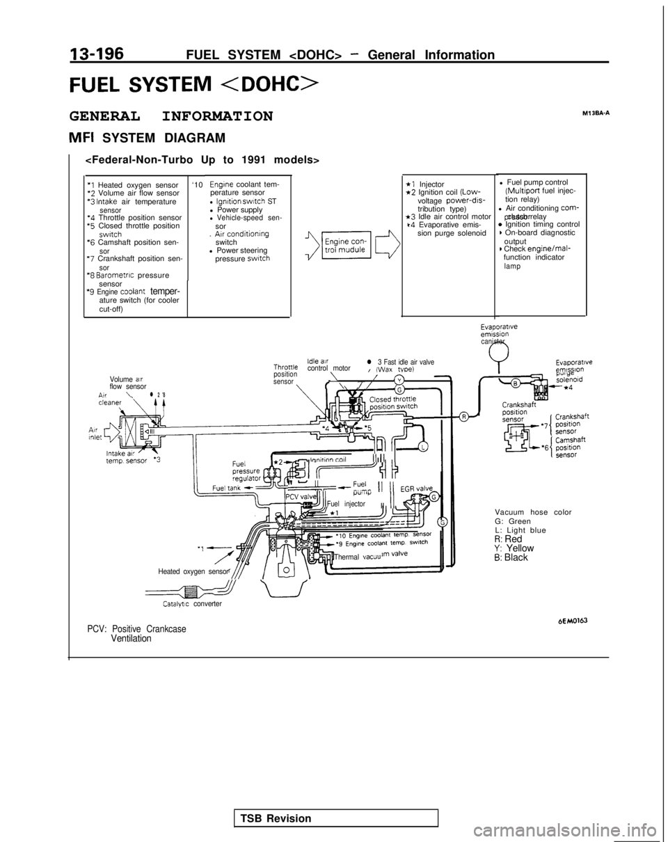
FUEL SYSTEM
GENERAL INFORMATION
MFI SYSTEM DIAGRAMMl
3BA-A
*1 Injector*2 Ignition coil
(Low-
voltage power-drs-
tribution type)
*3 Idle air control motork4 Evaporative emis-
sion purge solenoid l Fuel pump control (Multiport
fuel injec-
tion relay)
l Air conditioning
corm- pressor clutch relay
* Ignition timing control) On-board diagnostic
output
) Check engine/mal-
function indicator
lamp
Engine coolant tem-
perature sensor
l Ignition swatch STl Power supplyl Vehicle-speed sen-sor
. Arr conditioning
switch
l Power steering
pressure
swatch
‘I Heated oxygen sensor ‘10*2
Volume air flow sensor *3
Intake air temperaturesensor‘4 Throttle position sensor *5
Closed throttle position
swrtch *6
Camshaft position sen-
sor “7
Crankshaft position sen-
sor“8 Barometrrc pressure
sensor
‘9 Engine coolant temper-ature switch (for cooler
cut-off)
Evaporatrveemrssion canister
Evaporatrveemlsslo”Idle airThronlecontrol motorl 3 Fast idle air valveI (Wax tvoe)position\Volume air/sensor3flow sensorf \//n,r\l 2 '8
- lnnhnn toll III1 II
II-“,--?% 11 11 EGR,/alveI.l”lll)i
Fuel injectorII
II
Vacuum hose color
G: Green
L: Light blue
I?: RedY: Yellow5: Black
Heated oxygen sensor Thermal
vacuu
a uCatalytrc converter
HMO163PCV: Positive CrankcaseVentilation
TSB Revision
Page 339 of 1273
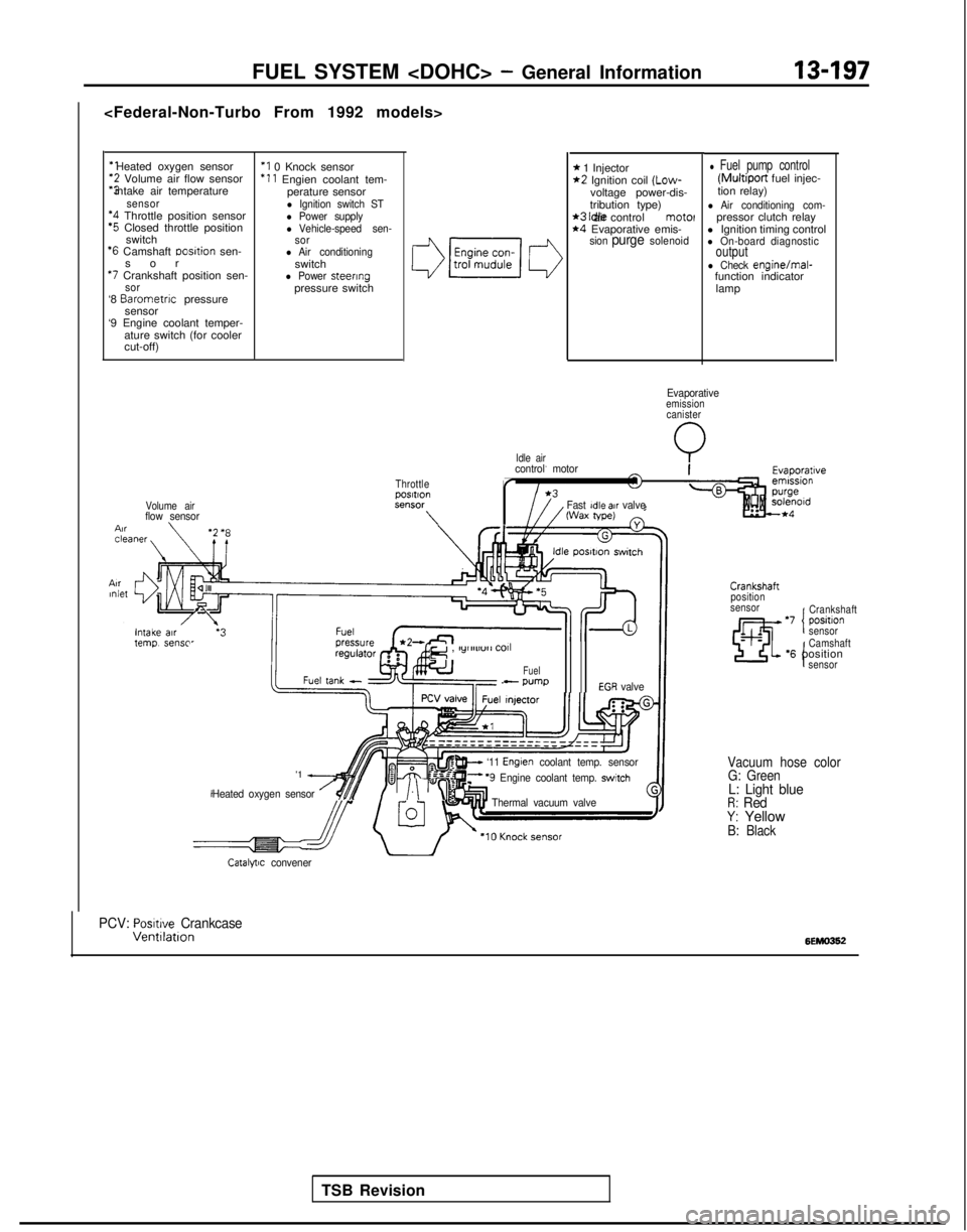
‘1 Heated oxygen sensor‘2 Volume air flow sensor
“3 intake air temperature
sensor‘4 Throttle position sensor‘5 Closed throttle position
switch
‘6 Camshaft Dosltion sen-
so
r
*7 Crankshaft position sen-sor‘8
Barometnc
pressure
sensor
‘9 Engine coolant temper-
ature switch (for cooler
cut-off)
‘I 0 Knock sensor ‘11
Engien coolant tem-
perature sensor
l Ignition switch STl Power supplyl Vehicle-speed sen-
sor
l Air conditioningswitchl Power steeringpressure switch
Volume airflow sensor \
Idle air
FUEL SYSTEM
* 1 Injector*2 Ignition coil (Low-
voltage power-dis-
tribution type)
*3 Idle air control motel*4 Evaporative emis-sion purge solenoid
l Fuel pump control (Multiport
fuel injec-
tion relay)
l Air conditioning com-pressor clutch relay
l Ignition timing control
l On-board diagnosticoutputl Check engine/mal-
function indicator
lamp
Evaporativeemissioncanister
Q
ThrottlepOSltlOnSt?“SW
\
control motor
r
Fast Idle air valveWax tape)
TSB Revision
e , lylllll”rl
COll
Fuel- wmpEGR valve
'1 A
Heated oxygen sensor /$$y/.\‘“I
w ‘11 Englen coolant temp. sensorF ‘9 Engine coolant temp. switch
Thermal vacuum valve
Crankshaft
position
sensor
‘7 positlon ICrankshaft
sensor
I
Camshaft‘6 positionsensor
Vacuum hose color G: Green
L: Light blueR: RedY: YellowB: Black
Catalytic convener
PCV: Posmve CrankcaseVentllatlon6EMO362