relay MITSUBISHI GALANT 1989 Service Workshop Manual
[x] Cancel search | Manufacturer: MITSUBISHI, Model Year: 1989, Model line: GALANT, Model: MITSUBISHI GALANT 1989Pages: 1273, PDF Size: 37.62 MB
Page 340 of 1273
13-198FUEL SYSTEM
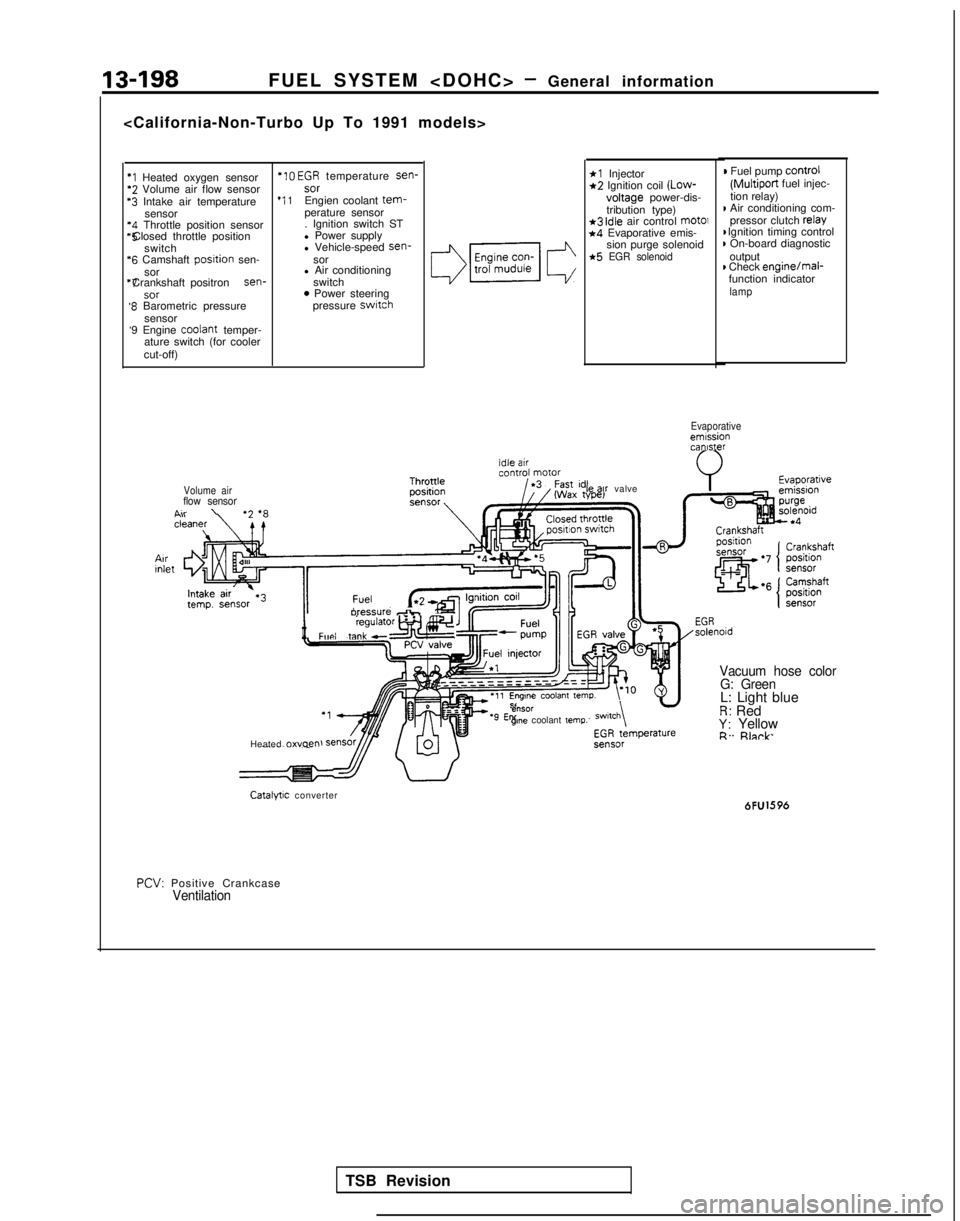
*I Heated oxygen sensor *IO
EGR temperature sen-*2 Volume air flow sensor
sor‘3 Intake air temperature
*I 1Engien coolant tem-sensor
perature sensor‘4 Throttle position sensor . Ignition switch ST*5 Closed throttle position
l Power supply
switch l Vehicle-speed sen-
‘6 Camshaft
posltion
sen- sor
sor l Air conditioning“7 Crankshaft positron sen-
switch
SOT0 Power steering‘8 Barometric pressure pressure switch
sensor
‘9 Engine coolant
temper-
ature switch (for cooler
cut-off)
*l Injector*2 Ignition coil (Low-
voltage
power-dis-
tribution type)
*3 idle air control mot01*4 Evaporative emis- sion purge solenoid
*5 EGR solenoid
) Fuel pump control
(Multiport
fuel injec-
tion relay)
I Air conditioning com- pressor clutch relay I Ignition timing control
) On-board diagnostic
output
) Check enginejmal-
function indicator
lamp
Evaporativeemissioncanister
Volume air
flow sensorA..\
II
oressure db,Fun, taw”l”‘“‘~
Heated 0~““~” le
ax valve
e”SOrgme coolant temp.
Vacuum hose color
G: Green
L: Light blueR: RedY: YellowR. Rlnrk
Catalytic converter 6FU1596
PCV:
Positive Crankcase
Ventilation
TSB Revision
Page 341 of 1273
FUEL SYSTEM
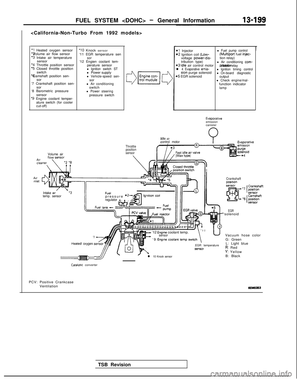
*1 Heated oxygen sensor *2 Volume air flow sensor
‘3 Intake air temperature
sensor *4
Throttle position sensor
‘5 Closed throttle position
switch *6 Camshaft position sen-
sor
‘7 Crankshaft position sen- sor
‘8 Barometric pressure
sensor
‘9 Engine coolant temper-ature switch (for cooler
cut-off)
Volume air
‘10 Knock sensor
‘11 EGR temperature sen
sor‘12 Engien coolant tem- perature sensor
l Ignition switch STl Power supplyl Vehicle-speed sen-sorl Air conditioningswitchl Power steeringpressure switch
3
Throttleposition
sensor
IIntake air.‘3Fueltemp. sensorpressure *2-regulatorA-
-
.
cd
’
*l Injectorl Fuel pump control*2 Ignition coil (Low- (Multiport
fuel injec-voltage power-dis-
tion relay)
tribution type)
*3 Idle air control motorl Air conditioning com-
l 4 Evaporative emis- pressor clutch relaysion purge solenoidl Ignition timing control
t5 EGR solenoidl On-board diagnosticoutputl Check engine/mal-function indicatorlamp
Idle
aircontrol motorI Wax
wei
I
I
TSB Revision
Evaporativeemission
canister
Heared oxygen
It=
‘12 Engine coolant temp.sensor-‘I u
‘9 Engine coolant temp switch\
l 10 Knock sensor
EGR temperature
Crankshaftposltlon
EGR‘solenoid Vacuum hose colorG: GreenL: Light blue
R: RedY: Yellow
B: Black
Catalfllc converter
PCV: Positive Crankcase Ventilation
Page 342 of 1273
13-200FUEL SYSTEM
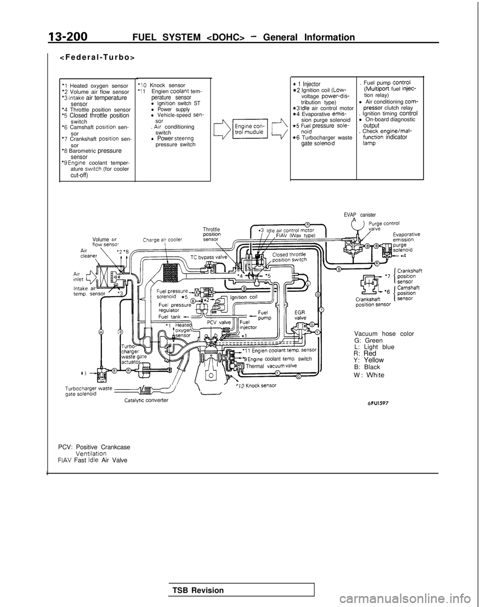
*l Heated oxygen sensor‘2 Volume air flow sensor*3 Intake air temperaturesensor‘4 Throttle position sensor‘5 Closed throttle positionswitch
*6
Camshaft posrtion sen-
sor
‘7 Crankshaft posrtion sen-
sor
‘8 Barometric pressuresensor “9
Engrne coolant temper-
ature swatch (for coolercut-off)
‘10 Knock sensor‘1 1Engien coolant
tem-perature sensorl lgnitton switch STl Power supplyl Vehicle-speed sen-sor. Arr conditioning
switch
l Power steeringpressure switch
Volume arrflow sensor
l 6
* 1 Injector. Fuel pump Control*2 Ignition coil (Low-(Multiport fuel injec-
voltage power-dis-tion relay)
tribution type) l Air conditioning com-
*3 Idle air control motor
pressor
clutch relay*4 Evaporative emis-
. Ignition timing control
sion purge solenoid l On-board diagnostic
*5 Fuel pressure sole-outputnoid. Check enginelmal-*6 Turbocharger wastegate solenoidf;r$ion indicator
EVAP canisterA
Throttle
9 Engine coolant temp. switch
Thermal VaCUUm valve
b;~ype; waste e-5 /I\- I”-
Catalyw converter
Vacuum hose color
G: Green
L: Light blue
R: RedY: Yellow
B: Black
W:
White
6FU1597
PCV: Positive CrankcaseVentilationFIAV Fast Idle Air Valve
I
TSB Revision
Page 343 of 1273
FUEL SYSTEM
I-
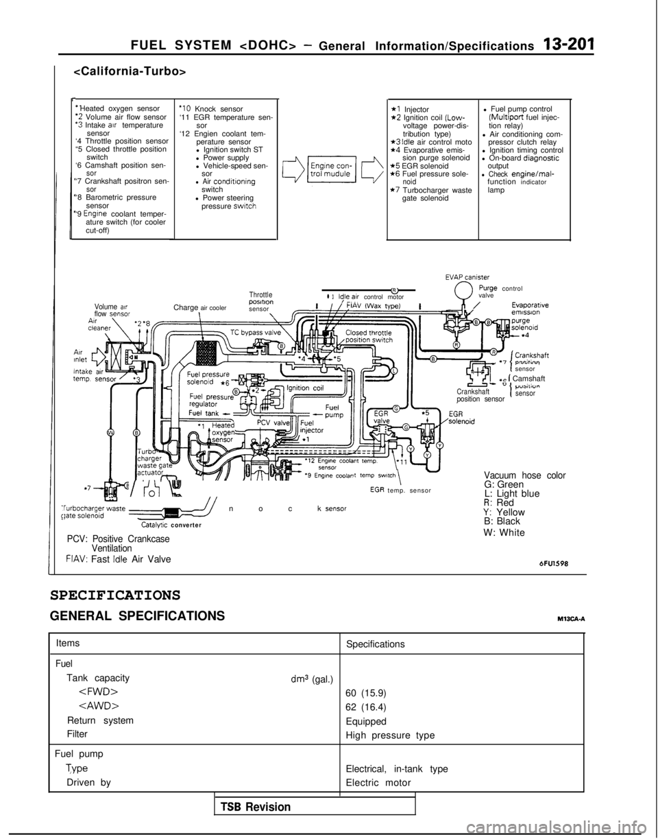
‘1 Heated oxygen sensor
‘2 Volume air flow sensor‘3 Intake arr temperature
sensor
‘4 Throttle position sensor
“5 Closed throttle position
switch
‘6 Camshaft position sen-
sor‘7 Crankshaft positron sen-sor‘8 Barometric pressure
sensor
‘9
Engrne coolant temper-
ature switch (for cooler
cut-off)
ArrInlet
lntaltern1
Volume airflow sensor
‘IO Knock sensor
‘11 EGR temperature sen- sor
‘12 Engien coolant tem- perature sensor
l Ignition switch ST
l Power supply
l Vehicle-speed sen- sor
l Air conditroningswitch
l Power steering pressure
swatch
Throttle
Charge air cooler posmon
sensor\\
*I Injector*2 Ignition coil (Low-
voltage power-dis-
tribution type)
*3 Idle air control moto*4 Evaporative emis- sion purge solenoid
*5 EGR solenoid*6 Fuel pressure sole-noid*7 Turbocharger waste
gate solenoid l Fuel pump control
(Multiport fuel injec-
tion relay)
l Air conditioning com- pressor clutch relay
l Ignition timing control
l On-board diaanostic
output
-l Check enginelmal-
function indicator
lamp
EVAxniy
&0
rurge controll 3ld,le,~ir control motor valve
,n/Evaporatrveemrssron
\tcln-^- temp. sensor
,Ir I-, . -,
sensor
7 ’ <‘I+c 1 Camshaft
Crankshaft1p”3111”I I
position sensorsensor
it
temp SWl,Ch\ -Vacuum hose color
t
WV:0 Knock sensor$bgha;ge;zte //
Catalyuc converter
G: Green
L: Light blue
R: RedY: Yellow
B: Black
PCV: Positive Crankcase
VentilationW: White
FIAV: Fast Idle Air Valve6FU1598
SPECIFICATIONS
GENERAL SPECIFICATIONSM13CA-A
Items
Fuel
Tank capacity
Return system
Filter
Fuel pump Type
Driven by Specifications
dm3 (gal.)
60 (15.9)
62 (16.4)
Equipped
High pressure type
Electrical, in-tank type
Electric motor
TSB Revision
Page 344 of 1273
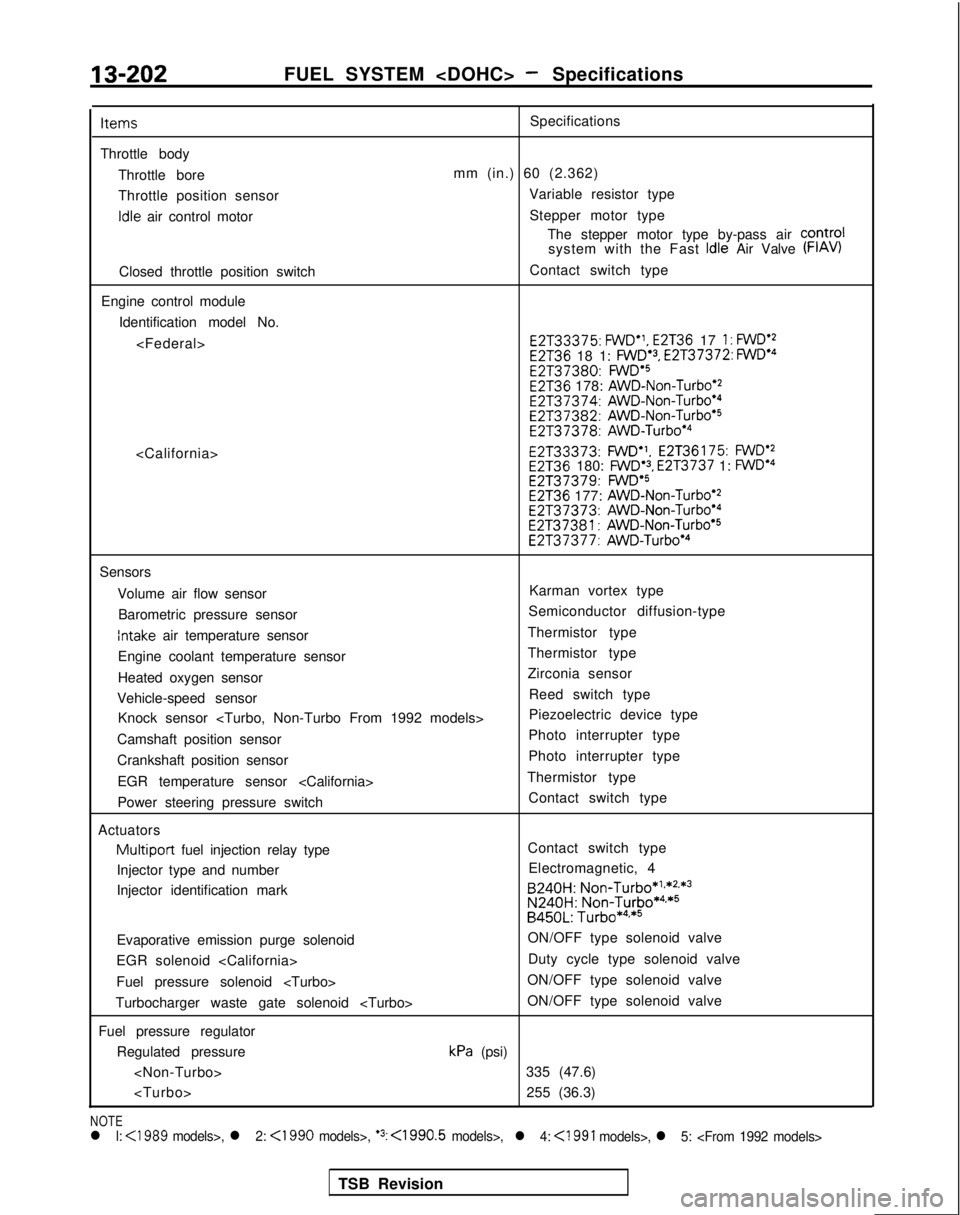
13-202FUEL SYSTEM
Throttle body Throttle bore
Throttle position sensor idle
air control motor
Closed throttle position switch
Engine control module Identification model No.
mm (in.) 60 (2.362) Variable resistor type
Stepper motor type The stepper motor type by-pass air COntrOl
system with the Fast
Idle Air Valve (FIAV)
Contact switch type E2T33375:
FWD”,
E2T36 17 1: FWD’2E2T36 18 1: FWD.3, E2T37372: FWDe4 E2137380:
FWDa5E2T36 178: AWD-Non-Turbo’2 E2T37374:
AWD-Non-Turboe4 E2T37382:
AWD-Non-Turbo*5 E2T37378:
AWD-Turbo’4 E2T33373:
FWD”.
E2T36175: FWDe2E2T36 180: FWD’3, E2T3737 1: FWDa4 E2T37379:
FWD’SE2T36 177: AWD-Non-Turbo’2 E2T37373:
AWD-Non-Turbo’4 E2T37381:
AWD-Non-Turbo’5 E2T37377:
AWD-Turbo*4
Sensors
Volume air flow sensor Karman vortex type
Barometric pressure sensor Semiconductor diffusion-type
Intake air temperature sensor
Thermistor type
Engine coolant temperature sensor Thermistor type
Heated oxygen sensor Zirconia sensor
Vehicle-speed sensor Reed switch type
Knock sensor
Camshaft position sensor Photo interrupter type
Crankshaft position sensor Photo interrupter type
EGR temperature sensor
Power steering pressure switch Contact switch type
Actuators
Multiport fuel injection relay type Contact switch type
Injector type and number Electromagnetic, 4
Injector identification mark B240H:
Non-Turbo*1**2.*3
N240H:
Non-Turbo*4,*5B450L: Turbo*4**5
Evaporative emission purge solenoid ON/OFF type solenoid valve
EGR solenoid
Fuel pressure solenoid
Turbocharger waste gate solenoid
Fuel pressure regulator Regulated pressure
kPa (psi)
NOTEl l: <1989 models>, l 2: <1990 models>, ‘3: <1990.5 models>,l 4:
<1991 models>, l 5:
TSB Revision
Page 349 of 1273
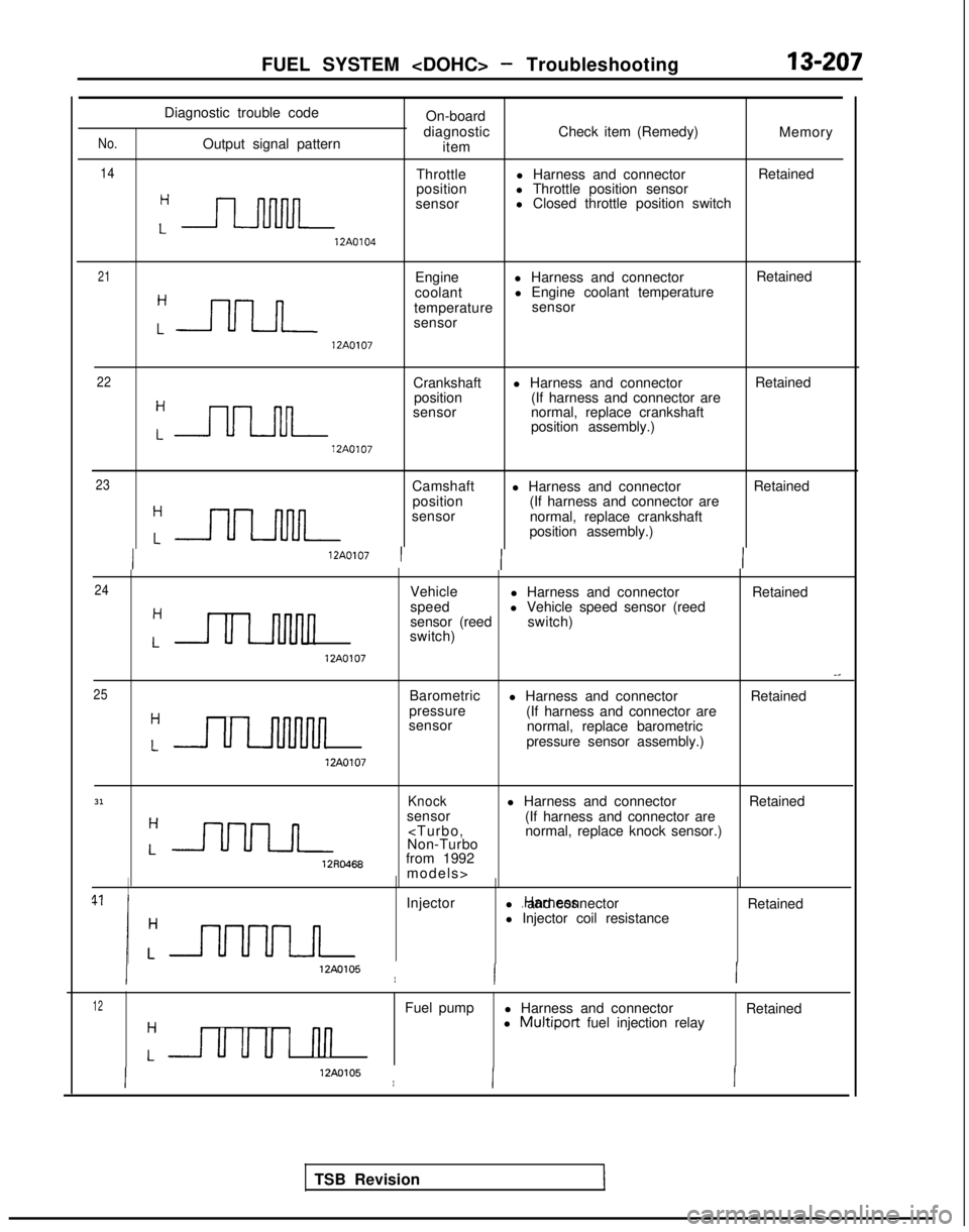
FUEL SYSTEM
No.
14
Diagnostic trouble code On-board
Output signal pattern diagnostic
item Check item (Remedy)
Memory
Throttle l Harness and connector Retained
:-
position
l Throttle position sensor
sensor l Closed throttle position switch
12A0104
21Engine
l Harness and connector Retained
:nn
coolant
l Engine coolant temperature
temperature sensor
sensor 12A0107
22Crankshaft
l Harness and connector Retained
:nn
position
(If harness and connector are
sensor normal, replace crankshaft
position assembly.) 12A0107
23Camshaft
position
sensor l Harness and connector
(If harness and connector are
normal, replace crankshaft
position assembly.) Retained 12A0107
I
24
25Vehicle l Harness and connector Retained
Hspeed
sensor (reedl Vehicle speed sensor (reed
Lswitch)
switch)
12A0107-.
Barometric
l Harness and connector Retained
H
ULJuuuvl
pressure
(If harness and connector are
sensor normal, replace barometric
Lpressure sensor assembly.) 12A0107
31Knockl Harness and connector
Retained
:-
sensor
12RO468from 1992
models>
Injector l .Harness and connector
l Injector coil resistance Retained
12AO105I
12Fuel pump
l Harness and connector Retained
Hl Multiport fuel injection relay
Luuul I-Ill
12AO105I
TSB Revision
Page 352 of 1273
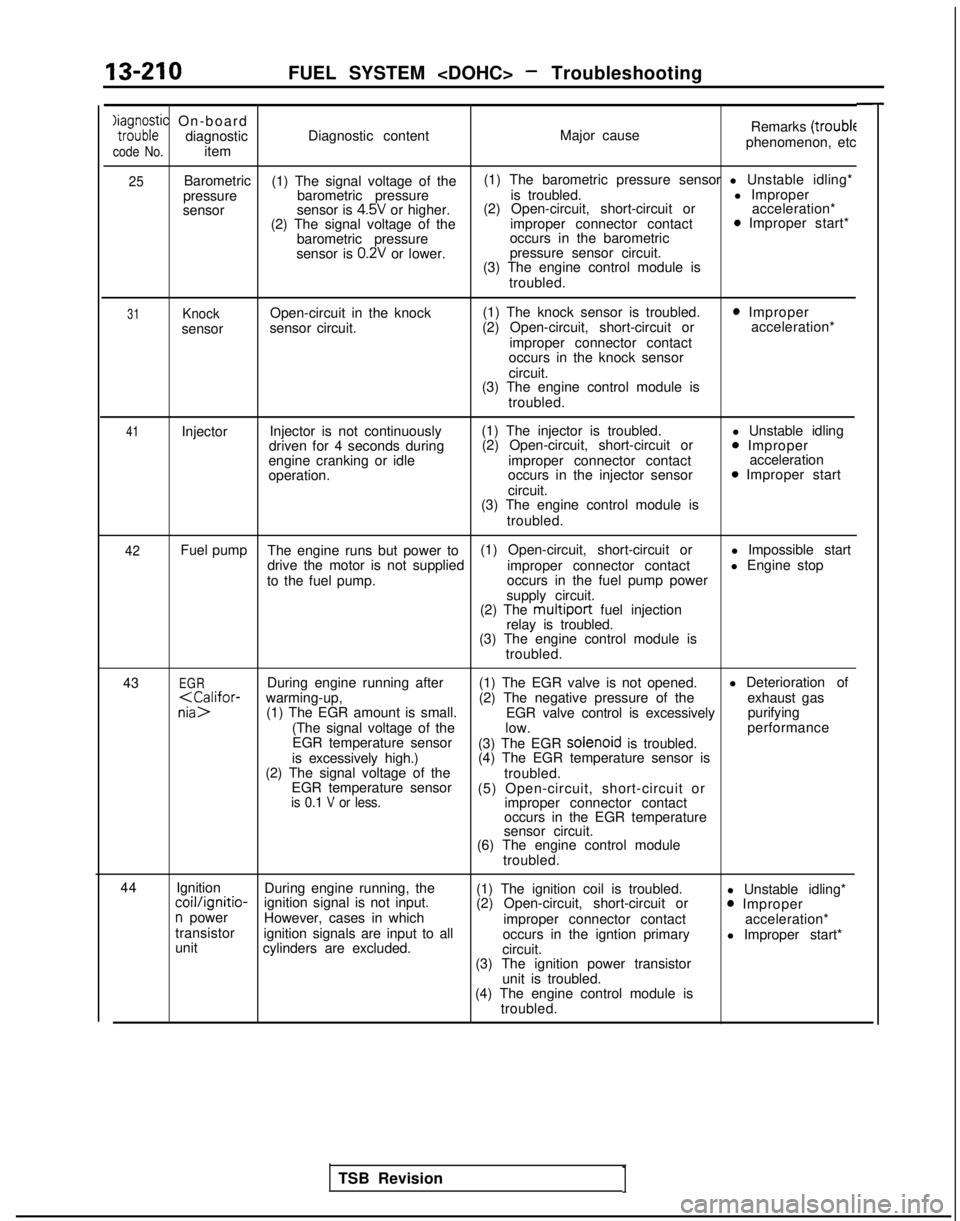
13-210FUEL SYSTEM
Xaia;;;ic On-boarddiagnostic
code No.item Diagnostic content
Major causeRemarks
(troublephenomenon, etc
25Barometric
(1) The signal voltage of the (1) The barometric pressure sensor l Unstable idling*
pressure barometric pressure is troubled. l Improper
sensor sensor is
4.5V or higher.(2) Open-circuit, short-circuit or
acceleration*
(2) The signal voltage of the improper connector contact0 Improper start*
barometric pressure occurs in the barometric
sensor is
0.2V or lower. pressure sensor circuit.
(3) The engine control module is
troubled.
31Knocksensor Open-circuit in the knock
sensor circuit. (1) The knock sensor is troubled.
(2) Open-circuit, short-circuit or
improper connector contact
occurs in the knock sensor
circuit.
0 Improper acceleration*
(3) The engine control module is troubled.
41Injector Injector is not continuously
driven for 4 seconds during
engine cranking or idle
operation. (1) The injector is troubled.
(2) Open-circuit, short-circuit or
improper connector contact
occurs in the injector sensor
circuit.
(3) The engine control module is
troubled. l Unstable idling0 Improper
acceleration
0 Improper start
42Fuel pump The engine runs but power to (1) Open-circuit, short-circuit or
l Impossible start
drive the motor is not supplied improper connector contactl Engine stop
to the fuel pump. occurs in the fuel pump power
supply circuit.
(2) The
multiport fuel injection
relay is troubled.
(3) The engine control module is
troubled.
43
EGRDuring engine running after (1) The EGR valve is not opened. l Deterioration of
EGR valve control is excessively purifying
(The signal voltage of the low. performance
EGR temperature sensor (3) The EGR solenoid
is troubled.
is excessively high.) (4) The EGR temperature sensor is
(2) The signal voltage of the troubled.
EGR temperature sensor (5) Open-circuit, short-circuit or
is 0.1 V or less.improper connector contact
occurs in the EGR temperature
sensor circuit.
(6) The engine control module
troubled.
44 Ignition
During engine running, the
(1) The ignition coil is troubled. l Unstable idling*
coil/ignitio-ignition signal is not input.
(2) Open-circuit, short-circuit or0 Impropern powerHowever, cases in which
improper connector contact acceleration*
transistor ignition signals are input to all
occurs in the igntion primaryl Improper start*
unit cylinders are excluded.
circuit.
(3) The ignition power transistor
unit is troubled.
(4) The engine control module is
troubled.
TSB Revision
1
Page 354 of 1273
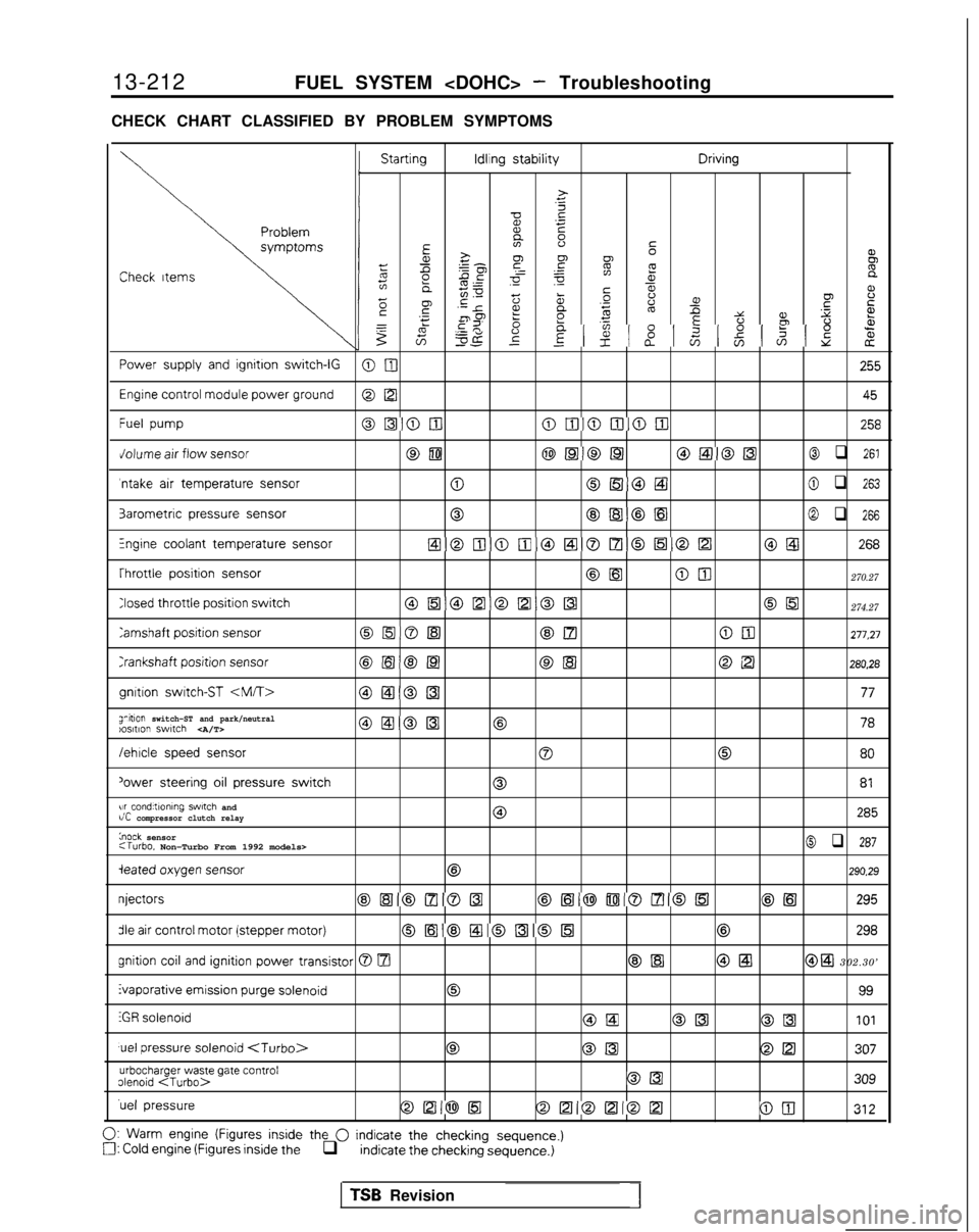
13-212
FUEL SYSTEM
CHECK CHART CLASSIFIED BY PROBLEM SYMPTOMS Starting Idling
stability Driving
>
.c
zx .-
E
EE 2-80’
52FCheck
Itemsz gp ~ =
gif8e
5;ms00 a,L%a‘;E
2
F5i5 .-
5scp ‘-re,t2aDo’6%.fP .xz YPfbz 2 ‘5 uE22
%il= 5
8
8 8gzzg-c$z8
z
Power
supply
and
ignition switch-IGOnI
255
Engine
control
module power ground
@ [ZI
45
Fuel
pumpoI51oulolIioDloiIl258
Jolume
air
flow sensorcam@Ea@@l@EilO[41@ q 261
‘ntake
air
temperature sensor0OlEiiOEtl@ q 263
3arometric
pressure
sensor0@lB@El@ q 266
Fngine coolant temperature sensorEloiIlomoaol7loEloDO@ 268
Throttle
position
sensor
@[email protected]
Closed throttle
position
switch0[51@D@D0[[email protected]
Tamshaft position
sensorOrnOlsl@Elam277,27
Crankshaft
position
sensor@El@[email protected]
gnltion
switch-ST
anitlon switch-ST and park/neutral)os,t,on switch @ElODl@ 78
/ehlcle
speed
sensor
00
80
‘ower
steering
oil
pressure
switch081
w conditlonlng swtch andr/C compressor clutch relay0285
knock sensor:Turbo. Non-Turbo From 1992 models>@ q 287
ieated oxygen
sensor
@290.29
njectors
@,[Hl@lzl@lz3@,161@Di080151@El
295
die air
control
motor (stepper
motor)0[63@!zl@al0863298 gnition
coil
and ignition
power transistor 0 m@El @El@ a 302.30’ Evaporative emission
purge
solenoid
0
99
iGR
solenoid@LaOK3@II3101
uel
pressure
solenoid
urbocharger waste gate contrololenoid
309
‘uel
pressureOD@l5l@D@D012100
312
0:
Warm
engine (Figures
inside
the 0 indicate the checking sequence.)a: Cold engine (Figures
inside
the q indicate
the checking
sequence.)
TSB Revision1
Page 358 of 1273

< 1989 models>
KTROLIGNITION POWER MFIUNIT TRANSISTORRELAY
,nr ,nrc n TD CT nv c!crw.fl\“l.I”mL c)I‘\ IAl””ULtll”JR\"/\")
13216FUEL SYSTEM
CIRCUIT DIAGRAM (CONTINUED)
< 1989 models>
KTROLIGNITION POWER MFIUNIT TRANSISTORRELAY
,nr ,nrc n TD CT nv c!crw.fl\“l.I”mL c)I‘\ IAl””ULtll”JR"/\2
,PTAKB *,A VOLUkz! FLOWIBOR
1.25-R
LI: CRANKSHAFT1 POSITION SENSORg AND CAMSHAFT
. POSITION SENSORa
A-57
\//1 I,t“3"5"4 "6 "1‘$1 '"3*54
t5Gk3s 6mI
z3m1,
WI
wm=-i !QIIII1*I
z-l t
' I
- ____-- J,-----3 I
m
ENGINE
%%&TURE
A-55 m“‘3
1 “&a,. YYI..d”..73 nnLxD-C”OXYGEN SENSORCHECK CONNECTOR
B c-14KX35-AC-H052SA-NY
TSB Revision
Page 360 of 1273
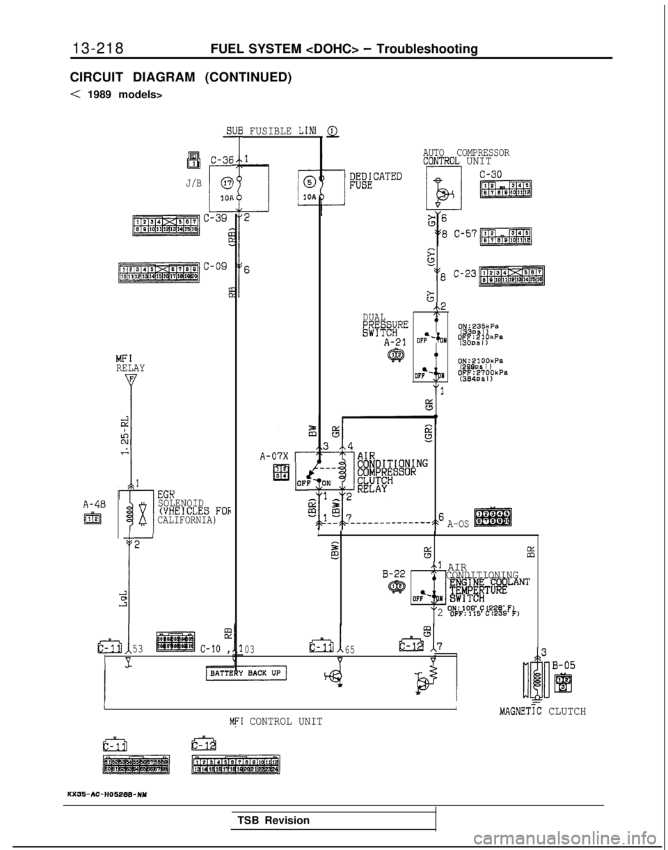
13-218
FUEL SYSTEM
CIRCUIT DIAGRAM (CONTINUED)
< 1989 models>
A-40
I@
aI3IC-36
J/B
r
@
101
MFIRELAY
I
i-l
EGK
x
SOLENOID(VHEICLES FOFCALIFORNIA)
2
r
631
ii!.?
53c-10 ,
V
I FUSIBLE LINl
A-07X r
Q
AUTO COMPRESSORCDNTROL UNIT s
52
218 C-23
G
..2DUAL,\
g;&#RE9~g,'~:yP"
A-21 OFb-‘;oN
~&~f~“‘”
@0ON:2100kPa
(299PS I )OFF:2700kPa(384PSl)
"I
F5
A-OSI
ss65iii
B-22~1 AIR" CONDITIONING
q@
XI ON:lOS'C(228'F2 OFF:115'C(239'k1
0365
YY
-IIMAGNETiC CLUTCHMFI CONTROL UNIT
KX35-AC-H05288-NY
TSB Revision