service MITSUBISHI GALANT 1989 Service Repair Manual
[x] Cancel search | Manufacturer: MITSUBISHI, Model Year: 1989, Model line: GALANT, Model: MITSUBISHI GALANT 1989Pages: 1273, PDF Size: 37.62 MB
Page 1244 of 1273
SERVICE BRAKES -Hydraulic Unit
w1480636
Pre-removal and Post-installation Op-
Flared brake line nuts 13-17 Nm
9-12 ft.lbs.
14FO38
17-26 Nm12- 19
ft.lbs.7- 10
ft.lbs.
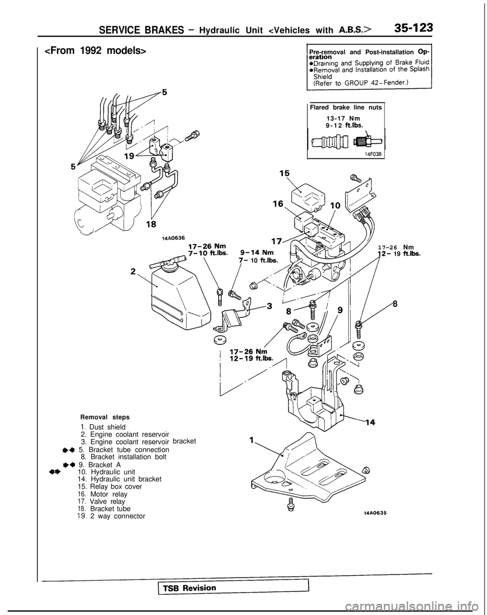
Removal steps
I. Dust shield
2. Engine coolant reservoir
3. Engine coolant reservoir
++ 5. Bracket tube connection 8. Bracket installation bolt
~~ 9. Bracket A4*10. Hydraulic unit
14. Hydraulic unit bracket
15. Relay box cover
16.Motor relay17.Valve relay18.Bracket tube19.2 way connector bracket
8
Page 1245 of 1273
35-124SERVICE BRAKES - Hydraulic Unit
I-Motor relay
16Fi1773
I___-
SERVICE POINTS OF REMOVAL
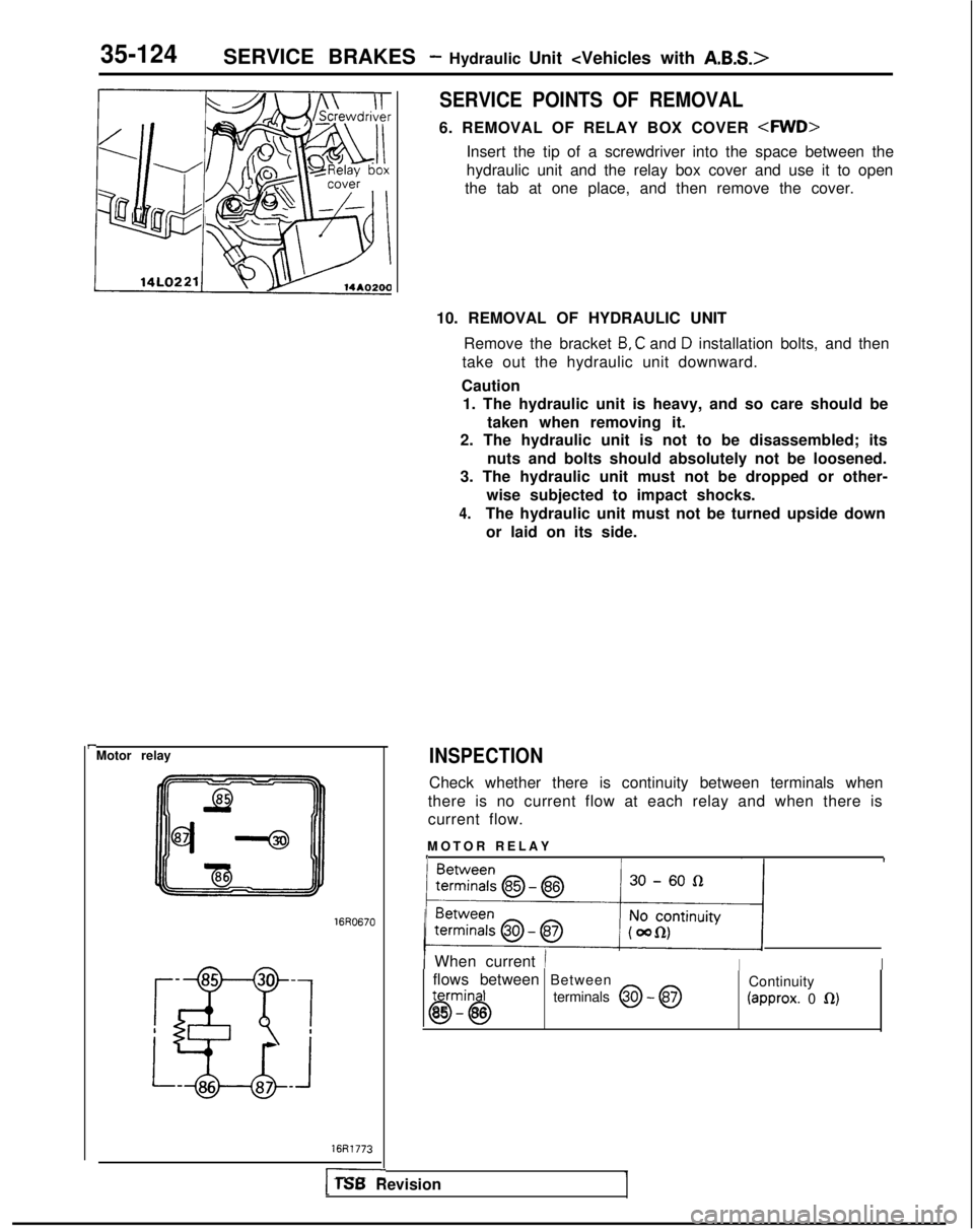
6. REMOVAL OF RELAY BOX COVER
Insert the tip of a screwdriver into the space between the
hydraulic unit and the relay box cover and use it to open
the tab at one place, and then remove the cover.
10. REMOVAL OF HYDRAULIC UNIT Remove the bracket
B, C and D installation bolts, and then
take out the hydraulic unit downward.
Caution 1. The hydraulic unit is heavy, and so care should be
taken when removing it.
2. The hydraulic unit is not to be disassembled; its
nuts and bolts should absolutely not be loosened.
3. The hydraulic unit must not be dropped or other-
wise subjected to impact shocks.
4.The hydraulic unit must not be turned upside downor laid on its side.
INSPECTION
Check whether there is continuity between terminals when
there is no current flow at each relay and when there is
current flow.
MOTOR RELA
Y
III
) 2ZSowsy/
( When current /IIflows between Betweentermin I
Continuity
0685 - 86terminals
@ - @ (approx.
0 0)
1 TSB Revision
Page 1246 of 1273
SERVICE BRAKES - Hydraulic Unit
Valve relay
16R0670
I16R1771
14AO201
1
I
U14AOlS9
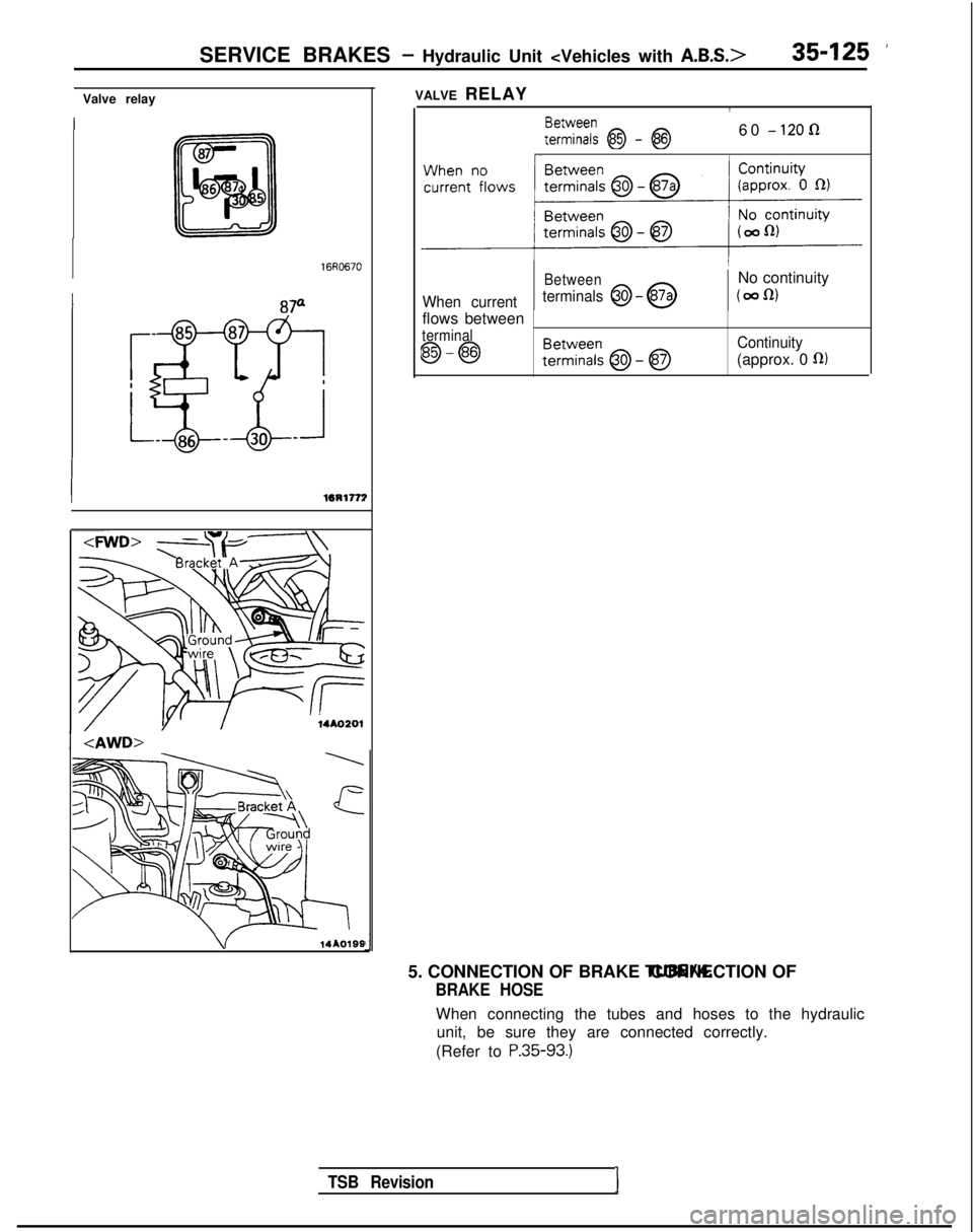
VALVE RELAY
FE%:; @ - @60 - 120 R
Between
No continuity
When current terminals @I - @(wfu
flows between
terminal
@I-@Continuity
(approx. 0 fl)
TSB RevisionI
5. CONNECTION OF BRAKE TUBE/4. CONNECTION OF
BRAKE HOSE
When connecting the tubes and hoses to the hydraulic
unit, be sure they are connected correctly.
(Refer to
P.35-93.)
Page 1247 of 1273
35-126 SERVICE BRAKES - Wheel Speed Sensor
WHEEL SPEED SENSOR
REMOVAL AND INSTALLATION
9-14 Nm
7-10 ft.lbs.
9- ldNm7- 10 ft.lbs.
~~Q!-yJl~~@
9-14 N
m
7- 10
ft.lbs.
14A0615
Pre-removal and Post-installation
Operation
@Removal and Installation of theSplash Shield(Refer to GROUP
42-Fender.)
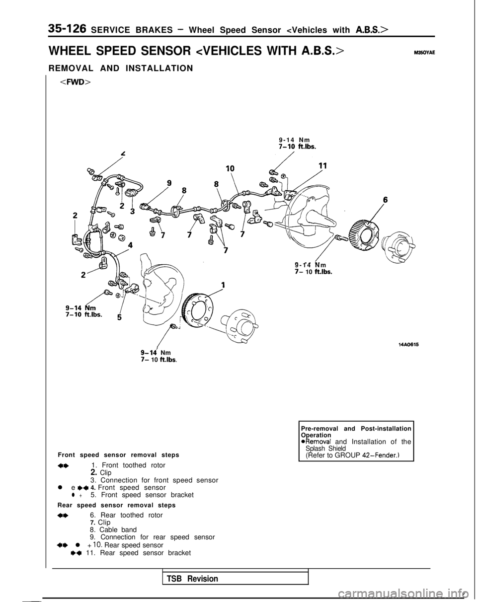
Front speed sensor removal steps
4w1. Front toothed rotor2. Clip3. Connection for front speed sensor
l e e+ 4. Front speed sensorl +5. Front speed sensor bracket
Rear speed sensor removal steps
*I)6. Rear toothed rotor 7. Clip
8. Cable band
9. Connection for rear speed sensor
+e l + 10. Rear speed sensorw+ 11. Rear speed sensor bracket
TSB Revision
/-..
Page 1248 of 1273
Pre-removal and Post-installation
SERVICE BRAKES - Wheel Speed Sensor
2
7-10 ftlbs.
7-10 ft.lbs.
9-14 Nm
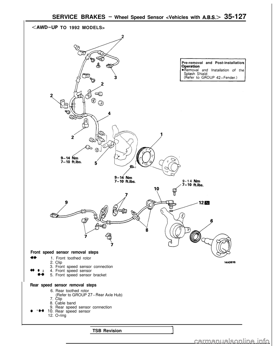
Front speed sensor removal steps
*I)1. Front toothed rotor
2. Clip
+* l a3. Front speed sensor connection
**4. Front speed sensor 5. Front speed sensor bracket
14AO616
Rear speed sensor removal steps
6. Rear toothed rotor (Refer to GROUP 27-Rear Axle Hub)
7. Clip
8. Cable band
l * I)49. Rear speed sensor connection10. Rear speed sensor
12. O-ring
TSB Revision
Page 1249 of 1273
35-128 SERVICE BRAKES - Wheel Speed Sensor
II 14AO215
Front speed sensor Rear speed sensorINSPECTION
Pole
hiecePole &ce
-
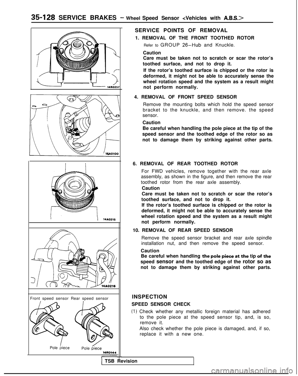
SERVICE POINTS OF REMOVAL 1. REMOVAL OF THE FRONT TOOTHED ROTOR Refer to GROUP
26-Hub and Knuckle.
Caution Care must be taken not to scratch or scar the rotor’s
toothed surface, and not to drop it.
If the rotor’s toothed surface is chipped or the rotor is
deformed, it might not be able to accurately sense the
wheel rotation speed and the system as a result might not perform normally.
4. REMOVAL OF FRONT SPEED SENSOR Remove the mounting bolts which hold the speed sensor
bracket to the knuckle, and then remove. the speed
sensor.
Caution
Be careful when handling the pole piece at the tip of the
speed sensor and the toothed edge of the rotor so as not to damage them by striking against other parts.
6. REMOVAL OF REAR TOOTHED ROTOR For FWD vehicles, remove together with the rear axle
assembly, as shown in the figure, and then remove the rear
toothed rotor from the rear axle assembly.
Caution
Care must be taken not to scratch or scar the rotor’s
toothed surface, and not to drop it. If the rotor’s toothed surface is chipped or the rotor is
deformed, it might not be able to accurately sense the
wheel rotation speed and the system as a result might not perform normally.
10. REMOVAL OF REAR SPEED SENSOR Remove the speed sensor bracket and rear axle spindle
installation nut, and then remove the speed sensor.
Caution Be careful when handling
the pole piece at the tip of the
speed sensor and the toothed edge of the
rotor so as
not to damage them by striking against other parts.
SPEED SENSOR CHECK
(1) Check whether any metallic foreign material has adhered to the pole piece at the speed sensor tip, and, is so,remove it.
Also check whether the pole piece is damaged, and, if so, replace it with a new one.
1 TSB Revision
Page 1250 of 1273
SERVICE BRAKES - Wheel Speed Sensor
:FWD>
Front
Rear (left)
Rear (right)
NOTE
14AOO46
The pole piece can become magnetized because of the
magnet built into the speed sensor, with the result that
metallic foreign material easily adheres to it. Moreover,
the pole piece may not be able to function to correctly
sense the wheel rotation speed if it is damaged.
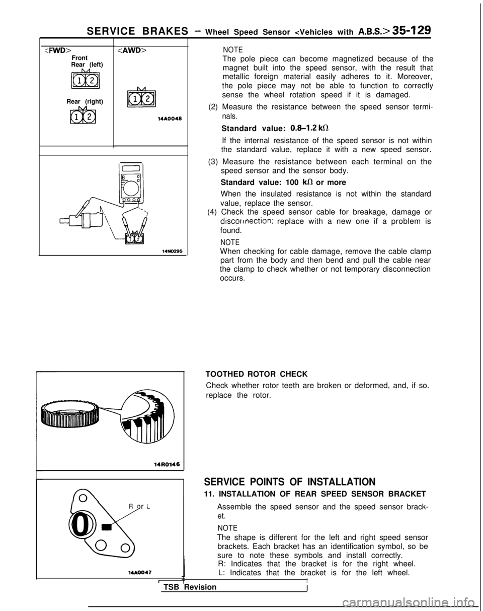
(2) Measure the resistance between the speed sensor termi-
nals. 14NO295
14R0146
R or L
%
0
00
14AOO47
ITSB RevisionStandard value:
0.8-1.2 ks1
If the internal resistance of the speed sensor is not within
the standard value, replace it with a new speed sensor.
(3) Measure the resistance between each terminal on the speed sensor and the sensor body.
Standard value: 100
kfI or more
When the insulated resistance is not within the standard
value, replace the sensor.
(4) Check the speed sensor cable for breakage, damage or discorrnection;
replace with a new one if a problem is
found.
NOTE
When checking for cable damage, remove the cable clamp part from the body and then bend and pull the cable near
the clamp to check whether or not temporary disconnection occurs.
TOOTHED ROTOR CHECK Check whether rotor teeth are broken or deformed, and, if so.
replace the rotor.
SERVICE POINTS OF INSTALLATION
11. INSTALLATION OF REAR SPEED SENSOR BRACKET
Assemble the speed sensor and the speed sensor brack-
et.
NOTE
The shape is different for the left and right speed sensorbrackets. Each bracket has an identification symbol, so be
sure to note these symbols and install correctly. R: Indicates that the bracket is for the right wheel.
L: Indicates that the bracket is for the left wheel.
I
I
Page 1251 of 1273
35-130 SERVICE BRAKES - Wheel Speed Sensor
Left side viewRight side
U 14AOO45
Left side view Left side
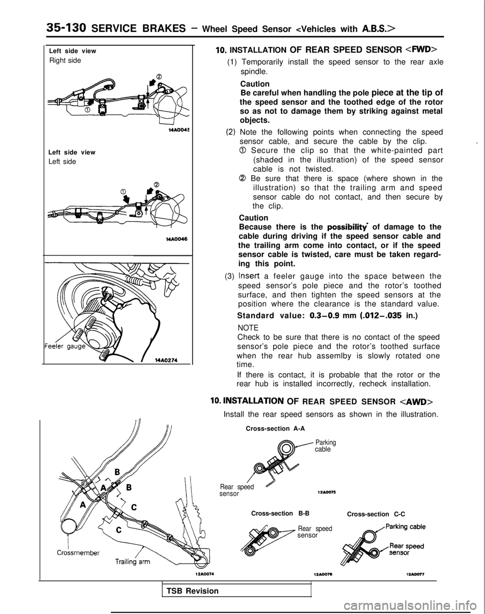
lo. INSTALLATION OF REAR SPEED SENSOR
(1) Temporarily install the speed sensor to the rear axle
spindle.
Caution Be careful when handling the pole piece at the tip of
the speed sensor and the toothed edge of the rotor so as not to damage them by striking against metal
objects.
(2) Note the following points when connecting the speed
sensor cable, and secure the cable by the clip.
0 Secure the clip so that the white-painted part
(shaded in the illustration) of the speed sensor
cable is not twisted.
0 Be sure that there is space (where shown in the illustration) so that the trailing arm and speed
sensor cable do not contact, and then secure by
the clip.
Caution
Because there is the
possibiliti of damage to the
cable during driving if the speed sensor cable and
the trailing arm come into contact, or if the speed sensor cable is twisted, care must be taken regard-
ing this point.
(3)
Inset-t a feeler gauge into the space between the
speed sensor’s pole piece and the rotor’s toothed
surface, and then tighten the speed sensors at the position where the clearance is the standard value.
Standard value:
0.3-0.9 mm (.012--035 in.)
NOTE
Check to be sure that there is no contact of the speed
sensor’s pole piece and the rotor’s toothed surface
when the rear hub assemlby is slowly rotated one
time.
If there is contact, it is probable that the rotor or the
rear hub is installed incorrectly, recheck installation.
10. INSTALLATION OF REAR SPEED SENSOR
Install the rear speed sensors as shown in the illustration.
Cross-section A-A
TSB Revision
Parkingcable
’ 2Rear speed
sensor1240076
Cross-section B-B Cross-section C-C
Rear speedsensor
Page 1252 of 1273
SERVICE BRAKES - Wheel Speed Sensor
0% 8
0 00
PT
00
6A
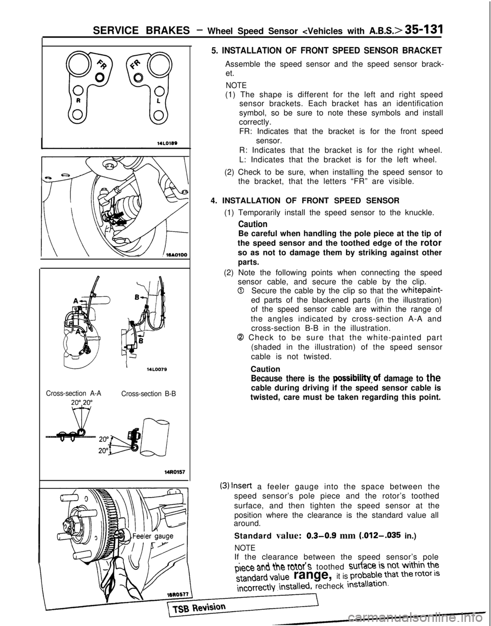
5. INSTALLATION OF FRONT SPEED SENSOR BRACKET
Assemble the speed sensor and the speed sensor brack-
et.
NOTE
(1) The shape is different for the left and right speed sensor brackets. Each bracket has an identification
symbol, so be sure to note these symbols and install
correctly.
FR: Indicates that the bracket is for the front speed sensor.
R: Indicates that the bracket is for the right wheel.
L: Indicates that the bracket is for the left wheel.
(2) Check to be sure, when installing the speed sensor to the bracket, that the letters “FR” are visible.
4. INSTALLATION OF FRONT SPEED SENSOR (1) Temporarily install the speed sensor to the knuckle.
Caution
Be careful when handling the pole piece at the tip of
the speed sensor and the toothed edge of the rotor so as not to damage them by striking against other
parts.
Cross-section A-A
(2) Note the following points when connecting the speed sensor cable, and secure the cable by the clip.
0Secure the cable by the clip so that the whitepaint-
ed parts of the blackened parts (in the illustration)
of the speed sensor cable are within the range of
the angles indicated by cross-section A-A and cross-section B-B in the illustration.
0 Check to be sure that the white-painted part
(shaded in the illustration) of the speed sensor
cable is not twisted.
I14L0079Caution
Because there is the possibilii~of damage to the
cable during driving if the speed sensor cable is
twisted, care must be taken regarding this point.Cross-section B-B 14Ro157
(3)
Insert
a feeler gauge into the space between the
speed sensor’s pole piece and the rotor’s toothed
surface, and then tighten the speed sensor at the
position where the clearance is the standard value all
around.
Standard value:
0.3-0.9 mm (.012-.035
in.)
NOTE
If the clearance between the speed sensor’s pole piece
ant\
the rotor’s toothed surtace
is not within the standard
value
range, it is probable
that the rotor
is
incorrect\Y
.insta\\ed,
recheck insta\iation-
Page 1253 of 1273
SERVICE BRAKES - G-Sensor
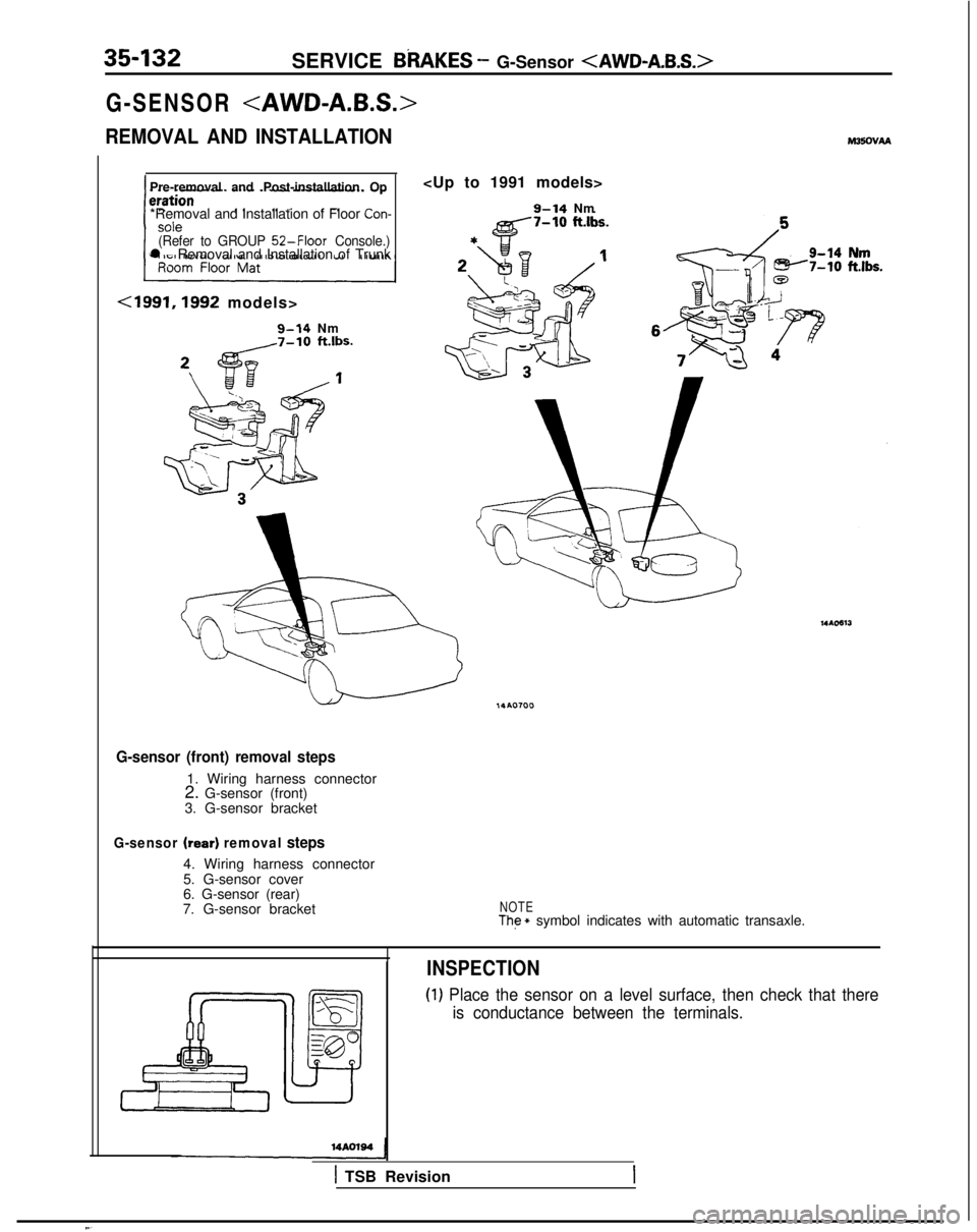
G-SENSOR
REMOVAL AND INSTALLATION
Pre-removal and Post-installation Op
*Removal and Installation of Floor
Con-
(Refer to GROUP
52-Floor Console.)l Removal and Installation of Trunk
<1991,1992 models>
g-14 Nm
M35OVAA
9-14 Nm
G-sensor (front) removal steps
1. Wiring harness connector
2. G-sensor (front)
3. G-sensor bracket
G-sensor (rear) removal steps
4. Wiring harness connector
5. G-sensor cover
6. G-sensor (rear)
7. G-sensor bracket
NOTEThe * symbol indicates with automatic transaxle.
INSPECTION
(1) Place the sensor on a level surface, then check that there
is conductance between the terminals.
1 TSB Revision