fuel pump MITSUBISHI GALANT 1989 Service Manual PDF
[x] Cancel search | Manufacturer: MITSUBISHI, Model Year: 1989, Model line: GALANT, Model: MITSUBISHI GALANT 1989Pages: 1273, PDF Size: 37.62 MB
Page 460 of 1273
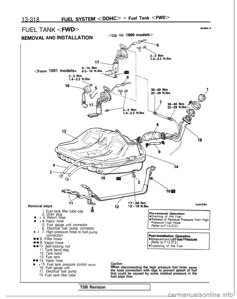
13-318FUEL SYSTEM
FUEL TANK
AND INSTALLATION
3
Removal steps 03A0284
1. Fuel tank filler tube cap2. Drain plugl + 3. Return hosel +
4. Vapor hose
5. Fuel gauge unit connector
6. Electrical fuel pump connector
l 47. High pressure hose to fuel pumpconnectionI)+ 8. Filler hose~1Weasuerment of Fuel PressureH 9. Vapor hose+4 10. Self-locking nut1 I. Tank band stay12. Tank band
13. Fuel tank
I)+ 14. Vapor hose
l + 15. Fuel tank pressure control valveCaution
16. Fuel gauge unitWhen disconnecting the high pressure fuel hose, cover
17. Electrical fuel pumpthe hose connection with rags to prevent splash of fuel
18. Fuel tank filler tube that could be caused by some residual pressure in thefuel pipe line.
TSB Revision1
Page 462 of 1273
13-320FUEL SYSTEM
03RO297
V/apor hose
mmin.)
3FOO7
Filler
hoseB
A
\Secure side 03YO43
Ll
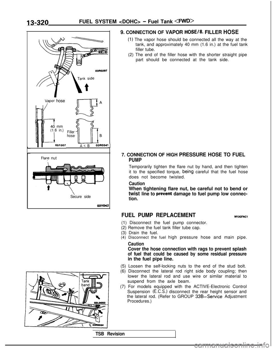
9. CONNECTION OF VAPOR HOSE/8. FILLER HOSE
(1) The vapor hose should be connected all the way at the
tank, and approximately 40 mm (1.6 in.) at the fuel tank
filler tube.
(2) The end of the filler hose with the shorter straight pipe part should be connected at the tank side.
7. CONNECTION OF HIGH PRESSURE HOSE TO FUEL
PUMP
Temporarily tighten the flare nut by hand, and then tighten
it to the specified torque,
bein,g careful that the fuel hose
does not become twisted.
Caution
When tightening flare nut, be careful not to bend or
twist line to prevent damage to fuel pump low connec-
tion.
FUEL PUMP REPLACEMENT
(1) Disconnect the fuel pump connector.
(2) Remove the fuel tank filler tube cap.
(3) Drain the fuel.
Ml3GFAt.X
(4) Disconnect the fuel high pressure hose and main pipe.
Caution
Cover the hose connection with rags to prevent splash
of fuel that could be caused by some residual pressure
in the fuel pipe line.
(5) Loosen the self-locking nuts to the end of the stud bolt.
(6) Disconnect the lateral rod right side body coupling; then
lower the lateral rod and use wire or similar material to
suspend from the axle beam.
(7) For models equipped with the ACTIVE-Electronic Control Suspension
(E.C.S.) disconnect the rear height sensor and
the lateral rod. (Refer to GROUP
33B-Service Adjustment
Procedures.)
TSB Revision
Page 463 of 1273
 Remove the fuel pump installation screws and the bolt for
holding the fuel")
FUEL SYSTEM
I03LOO18
-
QGB ua \
a=
C-CT
0a
c oc3i20’0Qaa
Positidning projection
03L0000
(8) Remove the fuel pump installation screws and the bolt for
holding the fuel pump (at the lower side of the fuel tank),
and then remove the fuel pump from the fuel tank.
(9) Align the three positioning projections of the packing with the holes in the fuel pump.
(lO)When the fuel pump is installed, the holding bolt at the
lower side of the fuel tank should be installed first. Care should be taken at this time that the O-ring is not
pinched.
(1 l)For models equipped with the ACTIVE-E.C.S., check the operation of the ACTIVE-E.C.S. after installation of the rear
height sensor. (Refer to GROUP
33B-Service Adjustment
Procedures.)
Page 464 of 1273
13-322FUEL SYSTEM
FUEL TANK
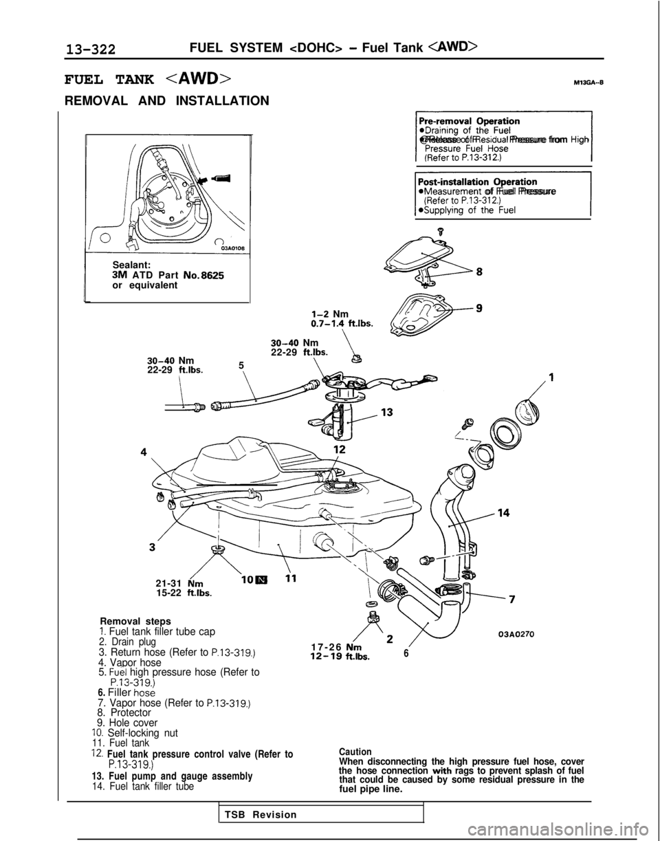
REMOVAL AND INSTALLATION
Sealant:
3M ATD Part No.8625or equivalent
30-40 Nm
22-29 ftlbs.
5
\\
\I@Release of Residual Pressure from High
11aMeasurement of Fuel Pressure
l-2 Nm0.7-1.4 ftlbs.\30-40 Nm
22-29 ftlbs.
\h
21-31 N/m15-22
ftlbs.
Removal steps
1. Fuel tank filler tube cap2. Drain plug3. Return hose (Refer to P.13-319.)4. Vapor hose 5. Fuel high pressure hose (Refer toP.13-319.1
17-2
6
12-1s
;~\*3~o,,.
Es.6
6. Filler
ho&7. Vapor hose (Refer to P.13-319.)8. Protector
9. Hole cover
IO. Self-locking nut11. Fuel tank
12. Fuel tank pressure control valve (Refer toP.13-319.)
13. Fuel pump and gauge assembly14. Fuel tank filler tube Caution
When disconnecting the high pressure fuel hose, cover
the hose connection with rags to prevent splash of fuel
that could be caused by some residual pressure in the
fuel pipe line.
TSB Revision
Page 465 of 1273
FUEL SYSTEM
03AOllO03AOlll
f%? hose
‘F;el high pressure
-Fuelgaugeand \n pump assembly- 03AO107
TSB Revision
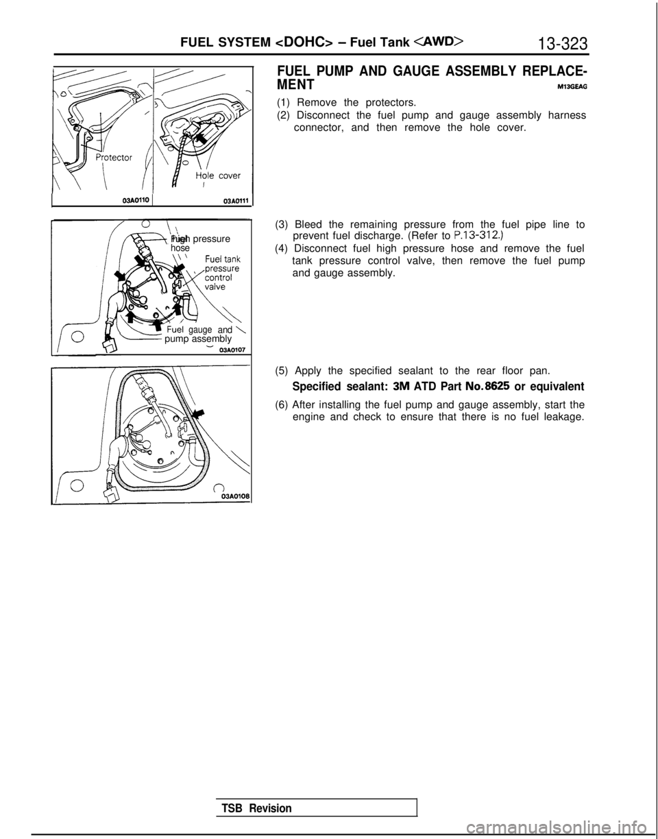
FUEL PUMP AND GAUGE ASSEMBLY REPLACE-
MENT
MlBGEAG
(1) Remove the protectors.
(2) Disconnect the fuel pump and gauge assembly harness connector, and then remove the hole cover.
(3) Bleed the remaining pressure from the fuel pipe line to prevent fuel discharge. (Refer to
P.13-312.)
(4) Disconnect fuel high pressure hose and remove the fuel
tank pressure control valve, then remove the fuel pumpand gauge assembly.
(5) Apply the specified sealant to the rear floor pan.
Specified sealant: 3M ATD Part No.8625 or equivalent
(6) After installing the fuel pump and gauge assembly, start the
engine and check to ensure that there is no fuel leakage.
Page 467 of 1273

t&-----Eye bolt
Gasket
Fuel filter
#-----
Flare nut
;y;; main ------A\
J")
FUEL SYSTEM
Mounting
bolts 03F008
I--l03FOO7Standard value: 20-25 mm (8-1.0 in.)
t&-----Eye bolt
Gasket
Fuel filter
#-----
Flare nut
;y;; main ------A\
J
I
-.
High-presfuel hose
J-ring
O”
SERVICE POINTS OF REMOVALMlSKBAMl
1. REMOVAL OF EYE BOLT
Remove the eye bolt while holding the fuel filter nut
securely.
Caution
Cover the hose connection with rags to prevent splash
of fuel that could be caused by some residual pressure
in the fuel pipe line.
3. REMOVAL OF FUEL FILTER (1) Loosen the main pipe flare nut while holding the fuelfilter nut securely.
(2) Remove the fuel filter mounting bolts, and then remove the fuel filter from the bracket.
INSPECTIONMlOKCABl
l Check the hose and pipes for cracks, bend, deformationand clogging.
lCheck the evaporative emission canister for clogging.
l Check the fuel filter for clogging and damage.
SERVICE POINTS OF INSTALLATIONMlJKDAPl
6. INSTALLATION OF FUEL VAPOR HOSE/4. FUEL RE-
TURN HOSE
(1) If the fuel pipe has a stepped part, connect the fuel
hose to the pipe securely, up to the stepped part, as
shown in the figure.
(2) If the fuel pipe does not have a stepped part, connect the fuel hose to the pipe securely, so that it is the
standard value.
3. INSTALLATION OF FUEL FILTER (1) When installing the fuel filter, first temporarily install thefilter to the filter bracket; then insert the main pipe at
the connector part of the filter, and manually screw in
the main pipe’s flare nut.
(2) Holding the fuel filter nut, tighten the fuel main pipe’s
flare nut and eye bolt at the specified torque. Then
tighten the filter to the bracket.
TSB Revision 2. INSTALLATION OF HIGH PRESSURE FUEL HOSE
Apply engine oil to the hose union.
Insert the hose, being careful not to damage the O-ring, and
tighten securely.
Caution
Because there is high pressure applied between the
fuel pump and the injection mixer, be especially sure
that there is no fuel leakage in this area.
Page 468 of 1273
13-326FUEL SYSTEM
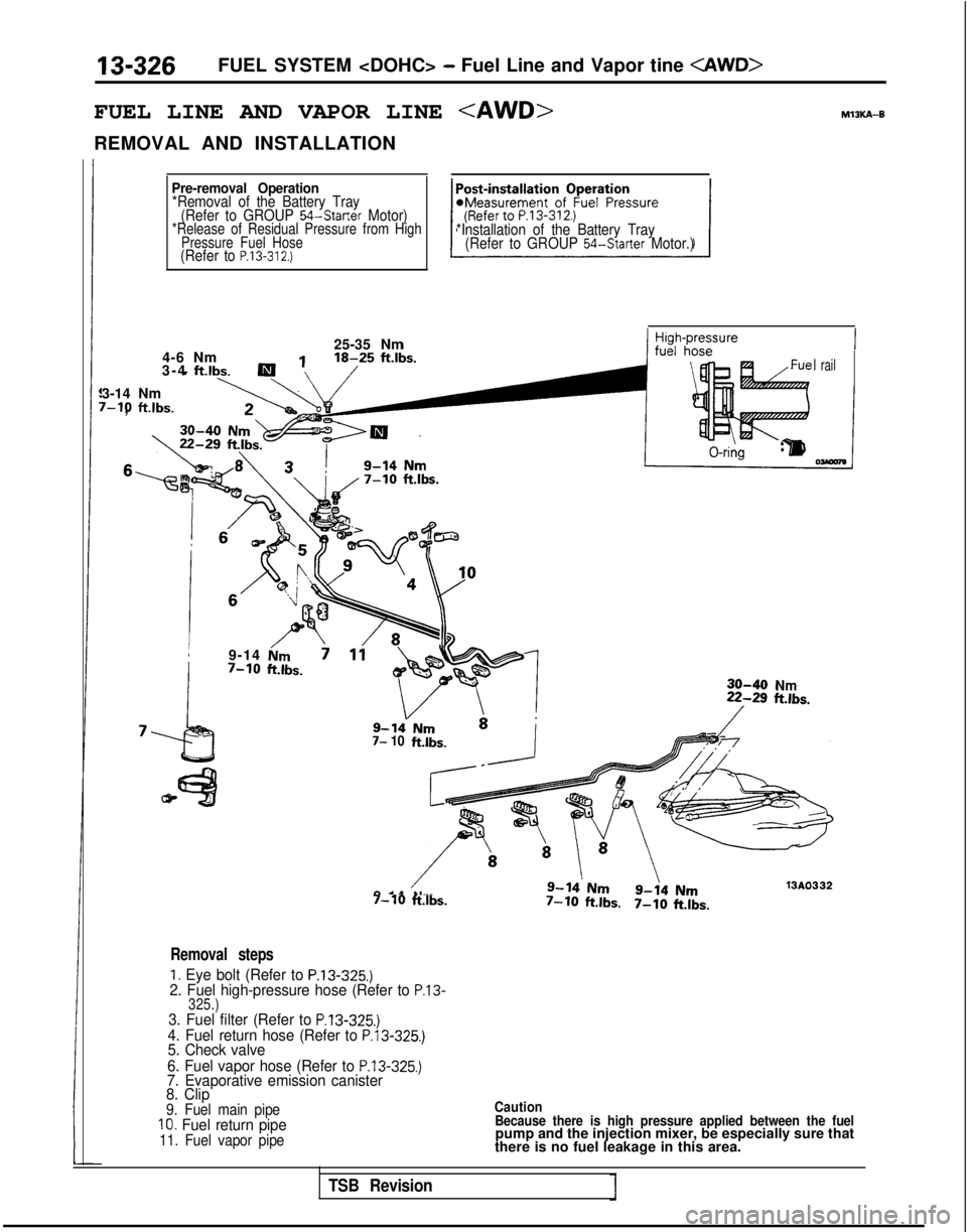
FUEL LINE AND VAPOR LINE
REMOVAL AND INSTALLATION
Pre-removal Operation*Removal of the Battery Tray(Refer to GROUP 54-Starter Motor)*Release of Residual Pressure from High Pressure Fuel Hose
(Refer to P.13-312.)
*Installation of the Battery Tray(Refer to GROUP 54-Starter Motor.)
25-35 Nm
4-6 Nm
3-4
ft.lbs.i
3-14 Nm v-10
ftlbs.
,
I rail
9-14rGm7-10ft.lbs.30-40Nm
7- 10 ftlbs.
13AO3329-14Nm7-10ft.lbs.7-10ft.lbs.7-10
ftlbs.
Removal steps
1. Eye bolt (Refer to P.13-325.)2. Fuel high-pressure hose (Refer to P.13-325.)3. Fuel filter (Refer to P.13-325.)4. Fuel return hose (Refer to P.13-325.)5. Check valve
6. Fuel vapor hose (Refer to
P.13-325.)7. Evaporative emission canister
8. Clip
9. Fuel main pipe10. Fuel return pipe11. Fuel vapor pipe Caution
Because there is high pressure applied between the fuelpump and the injection mixer, be especially sure that
there is no fuel leakage in this area.
TSB Revision
Page 641 of 1273

EMISSION CONTROL SYSTEMS -Evaporative Emission Control System17-21EC1510
6EM137
EVAPORATIVE EMlS$lON
PURGE SOLENOID
INSPECTIONM17lBFD
NOTE
When disconnecting the vacuum hose, make an identification
mark on it so that it can be reconnected to the original posi-
tion.
(1) Disconnect the vacuum hoses (non stripe and red stripe
hoses) from the solenoid valve
(2) Disconnect the harness connector from solenoid valve.
(3) Connect a hand vacuum pump to the nipple to which the red-striped vacuum hose was connected.
(4) Apply a vacuum and check for air-tightness when voltage applied directly to the evaporative emission purge solenoid
when the voltage is discontinued.
Battery voltageResult
Non-Turbo When appliedVacuum leaks
When discontinued Vacuum is maintained
TurboWhen appliedVacuum is maintained
When discontinued Vacuum leaks
(5) Measure the resistance between the terminals of the sole-
noid valve.
Standard value: 36-44 Q [at 20°C (68”F)l
VOLUME AIR FLOW SENSOR, ENGINE
COOLANT TEMPERATURE SENSOR AND
INTAKE AIR TEMPERATURE SENSOR
M17IBGB
To inspect these parts, refer to GROUP 13-On-Vehicle Inspec-
tion of
MFI Components.
AIR CONDITIONING SWITCH Ml7IBHB
To inspect the air conditioning switch, refer to GROUP
55-Air
Conditioning Switch.
FUEL TANK PRESSURE CONTROL VALVE MI’IIBEB
To inspect the fuel tank pressure control valve, refer to GROUP
13-Fuel
Tank.
EVAPORATIVE EMISSION CANISTERM17lBlB
To inspect the evaporative emission canister, refer to GROUP
13-Fuel Line and Vapor Line.
FUEL TANK FILLER TUBE CAP INSPECTIONM,7,w~
Check the gasket of the fuel tank filler tube cap, and the filler
cap itself, for damage or deformation; replace the
cap if neces-
sary.
TSB RevisionI
Page 1265 of 1273
4ALPHABETICAL INDEX
DOHC-Turbo.................................
. 15-31-f
SOHC-8VALVE..................................
.
15-27-t
SOHC-1 GVALVE............................
.
15-28-l
EXHAUST PIPEDOH
C
......................... 15-33-I
SOHC.....................................
.
15-32-l
EXHAUST SYSTEM, Maintenance ..................... 00-45-I
F
FAN MOTOR
Condenser
.............................
.
55-48-l
Radiator...................
.
......... 14-12-I
FEEDER CABLE ..........................
54-l 55-11FENDER................................
.
42-61-t
FILLER DOOR, Fuel Tank.........................
.
42-60-I
FILLER TUBE CAP, Fuel Tank, Inspection...............
.
17-21 -I
FILTER
Engine 011. Maintenance ....................
. 00-41-I
Fuel
Fuel
.
...................
13-I 15-lFuel
.
13-195
FITTINGS, Handling................................
. 55-22-l
FIXED SAS
Adjustment
........................
.
13-250-I
Adjustment
.
13-138-I
FLAT BATTERY, Remedy............................
.
35-75-l
FLOOR CONSOLE................................
.
52-29-l
FLUID
Power Steering, Level Check
...................
. 37A-21-l
Power Steering, Replacement ................. 37A-21-l
Transaxle, Replacement ..................... 23-82-l
FLUID LEVEL, Transaxle, Inspection .................. 23-82-l
FOG LIGHT................
.
......................
54-94-11FOG LIGHT SWITCH................................
.
54-99-114WS, Function Check
..........................
. 37B-6-l
FRONT BRAKE DISC
Run-out Check
...................................
. 35-63-I
Run-out Correction ........................... 35-64-l
Thickness Check .............................. 35-65-l
FRONT DISC BRAKE.................................
. 35-94-l
FRONT DISC BRAKE PAD, Check and Replacement ......... 35-59-l
FRONT DOOR DRIP LINE WEATHERSTRIP 42-112-I
FRONT DOOR GLASS...............................
. 42-80-l
FRONT DOOR HANDLE.........................
. 42-96-l
FRONT DOOR LATCH...
.
......... .......... 42-96-l
FRONT DOOR
MOULDING
........................... 42-112-I
FRONT DOOR REGULATOR........................
. 42-80-I
FRONT DOOR TRIM.................................
. 42-76-l
FRONT DOOR WATERPROOF FILM....................
. 42-76-l
FRONT GRILLE..................................
. 51-12-l
FRONT SEAT,...................................
. 52-35-l
FRONT WHEEL ALIGNMENT Adjustment
. 338-86-I
Adjustment
FUEL FILTER
DOHC
.......................................
. 13-327-I
SOHC-8VALVE
.................................
13-l 15-l SOHC-IGVALVE
................................ 13-195-I
FUEL HOSES, Maintenance ............................
00-39-1
FUEL LINE
DOHC-AWD ..................................
.
13-326-l
DOHC-FWD....................................
.
13-324-l
SOHC-8VALVE
................................. 13-113-l
SOHC-1 ~VALVE............................
.
13-l 95-IFUEL PRESSURE
On-vehicle Inspection
On-vehicle Inspection
On-vehicle Inspection
FUEL PRESSURE SOLENOID
On-vehicle Inspection
FUEL PUMP
On-vehicle Inspection
On-vehicle Inspection
On-vehicle Inspection
FUEL SYSTEM, Maintenanc
e
FUEL TANK
DOHC-AWD .,.......
DOHC-FW
D
SOHC-8VALVE
SOHC-16VALVE
FUEL TANK FILLER DOO
R
FUEL TANK FILLER TUBE CAP, Inspection
FUEL TANK PRESSURE CONTROL VALVE. 13-312-l
13-102-I
,.....13-I
92-l
13-307-I
......
13-258-l
....... 13-46-l
...... 13-147-l
....... 00-39-l
......
13-322-l
...... 13-318-l
..... 13-109-I
...... 13-195-I
....... 42-60-I
....... 17-21-I
....... 17-21-l
G
GARNISHES
51-13-l
GASKET
Cylinder Head
Cylinder Head
GAUGE UNIT, Engine Coolant Temperature
14-31-l
GEAR BOX, Power Steering 37A-32-l
GEAR OIL, Level Check
GENERATOR
16-g-11
GLASS
Door, Adjustmen
t
42-52-l
Door, Front 42-80-I
Door, Rear 42-83-l
Quarter Window 42-70-I
Window.............
.._......_...... 42-63-i
Window,Rear
42-72-i
GRILLE,Front
_. _. _.
51-12-l
G-SENSOR
Service Brakes
35-132-l
Output Voltage, Check 336-96-l
H
HANDLE
Door, Front
..........................
.
Door,Rear
...........................
Door Inside, Play Check. ..................
HAZARD SWITCH.........................
.
HEADLIGHTS............................
.
HEADLINING.............................
.
HEATED OXYGEN SENSOR, On-vehicle Inspection
>
...............................
HEATER CONTROL.......................
.
HEATER UNIT............................
.
HEIGHT SENSOR.........................
.
HIGH MOUNTED STOP LIGHT...............
.
42-96-1 42-99-l
42-52-l
54-98-11
54-92-11
52-31-l
13-290-I
55-25-l
55-30-I
338-l
35-l
54-96-11HIGH PRESSURE SWITCH (HIGH-PRESSURE TANK SIDE),Actuation Pressure Check. 338-94-I
16-42-11
42-55-l
42-50-I
54-l 03-11
54-105-11
HIGH TENSION CABLE, Spark Test
HOOD .__...._..._......__._...................
HOOD, Alignment Adjustment .
HOR
N
. . . . . . . . . . . . . . . . . . . . . . . . . . . . . . . . . . . . \
. . . HORNRELAY
._.._._....___.........__.._._..___
HOSE
Brake, Maintenance
.
00-45-I
Page 1268 of 1273
ALPHABETICAL INDEX
PLUGSpark, Maintenance. 00-40-I
Spark, Test..
16-42-11
POSITIVE CRANKCASE VENTILATION SYSTEM 17-13-l
POSITIVE CRANKCASE VENTILATION (PCV) VALVE,Inspection
17-14-I
POWER AMPLIFIER
54-151-11POWER CYLINDE
R
378-9-I
POWER GROUND
Engine Control Module, On-vehicle
Inspection
Engrne Control Module, On-vehicle Inspection
.
13-45-l
Engine Control Module, On-vehicle Inspection
.
13-146-I
POWER RELAY
ABS. Check
................................
.
35-74-l
Air
Conditionrng and Ventrlation. Check ........
.
55-24-l
POWER STEERING, Stationary Steering Effort Check......
.
37A-18-l
POWER STEERING FLUID
Level Check
.................................
.
37A-21-l
Replacement .................................... 37A-21-I
POWER STEERING GEAR 80X....................
.
37A-32-l
POWER STEERING HOSES...........
.
........ 37A-58-l
POWER STEERING OIL PUMP......................
.
37A-48-l
POWER STEERING OIL PUMP, Pressure Test...........
.
37A-23-l
POWER STEERING PRESSURE SWITCH
Check
........................................
.
37A-24-l
On-vehicle Inspection
On-vehicle Inspection
.
13-81 -IOn-vehicle Inspection
.
13-175-l
POWER SUPPLY
On-vehicle Inspectron
.................
.
13-255-l
On-vehicle Inspection
.
13-42-I
On-vehrcle Inspection
.
13-143-l
POWER TRANSISTOR
Ignition, On-vehicle Inspection
............
.
13-302-I
Ignition, On-vehicle Inspection
.
13-96-l
Ignition, On-vehicle Inspection
POWER WINDOW..................................
.
42-86-l
PRESSURECompression, Check
....................
.
11-59-i
Compression, Check
1 l-8-lFuel, On-vehicle Inspection
.
13-312-I
Fuel, On-vehicle Inspection
.
13-102-I
Fuel, On-vehicle Inspection
.
13-192-l
Inflation,Tire,
Check
............................ 31-4-I
Line, Adjustment .................................. 23-88-l
Reducing, Adjustment ........................
23-91 -IPRESSURE SWITCH
Brake Fluid
....
.
35-133-I
Brake Fluid, Check AWD-ABS: Up to 1991 Models> ..... 35-75-l
PROPELLER SHAFT.................................
.
25-4-l
PROPORTIONING VALVE, Function Test................
.
35-56-l
PUMP
Fuel, On-vehicle Inspection
Fuel, On-vehicle Inspection
.
13-46-l
Fuel, On-vehicle Inspection
.
13-147-l
OiLRear
....................................... 37B-15-l
Water
................................ 14-20-I
Water
14-I 5-1PURGE CONTROL SYSTEM
Inspection
.........................
.
17-17-I
Inspection
PURGE CONTROL VALVE
PURGE PORT VACUUM............................
.
17-19-I
Q
QUARTER WINDOW GLASS......................
.
42-70-I
R
RADIATOR.........................................
.
14-9-lRADIATOR CAP, Pressure Test
.......................
.
14-8-lRADIATOR FAN MOTOR
............................
.
14-12-lRADIO AND TAPE PLAYER
..........................
.
54-149-11REAR AXLE
Maintenance
.............................
.
00-45-I
Total Backlash Check
.
27-15-I
REAR AXLE HUB
FWD-Rear Disc Brakes
.............................
.
27-8-l
FWD-Rear Drum Brakes ........................... 27-6-l
REAR BRAKE DISC
Run-out Check.
.................................
.
35-66-l
Run-out Correction .............................. 35-66-l
Thickness Check ............................... 35-66-l
REAR BRAKE WHEEL CYLINDER......................
.
35-l 1 l-lREAR COMBINATION LIGHT
..........................
.
54-95-IREAR DISC BRAKE.................................
.
35-l 14-lREAR DISC BRAKE PAD, Check and Replacement
.........
. 35-65-l
REAR DOOR DRIP LINE WEATHERSTRIP.............
.
42-l 14-lREAR DOOR GLASS.........................
.
42-83-l
REAR DOOR HANDLE............................
.
42-99-l
REAR DOOR LATCH................................
.
42-99-l
REAR DOOR
MOULDING
........................42-l 14-l
REAR DOOR REGULATOR..........................
.
42-83-l
REAR DOOR TRIM................................
.
42-78-l
REAR DOOR WATERPROOF FILM......................
.
42-78-l
REAR DRUM BRAKE...............................
.
35-108-I
REAR DRUM BRAKE LININGS, Maintenance ............... 00-44-I
REAR HUB, Rotary-sliding Resistance (Torque)
Adjustment
.
27-5-l
REAR OIL LINE..................................
.
378-13-I
REAR OIL PUMP
Discharge Flow Volume Check .................... 378-6-I
4WS
........................................... 378-15-I
REAR SEAT......................................
.
52-37-l
REAR SUSPENSION
Active-ECS
...................................
.
338-l 14-lAWD
..........................................
.
34-24-l
FWD..........................................
.
34-6-l
REAR WHEEL ALIGNMENT Inspection
.
34-23-l
Inspection
.
34-5-l
REAR WHEEL BEARING
End Play Check
.
27-15-I
‘Rotation Sliding Resistance Check
.
27-16-I
REAR WHEEL CYLINDERS, Maintenance, 00-44-I
REAR WINDOW
DEFFOGER..........................
.
54-156-11REAR WINDOW DEFOGGER SWITCH..................
.
54-163-11REAR WINDOW GLASS..............................
.
42-72-l
REDUCING PRESSURE, Adjustment. ..................... 23-91-l
REFRIGERANT, Leak Repair Procedure.................
.
55-21-l
REFRIGERANT LINE..................................
55-54-l
REGULATOR
Door, Front
.....................................
.
42-80-I
Door, Rear ....................................... 42-83-l
RELAY
A/C Compressor Clutch, On-vehicle Inspection
.
13-83-lA/C Compressor Clutch, On-vehicle Inspection
13-176-I