fuel pump MITSUBISHI GALANT 1989 Service Manual PDF
[x] Cancel search | Manufacturer: MITSUBISHI, Model Year: 1989, Model line: GALANT, Model: MITSUBISHI GALANT 1989Pages: 1273, PDF Size: 37.62 MB
Page 393 of 1273
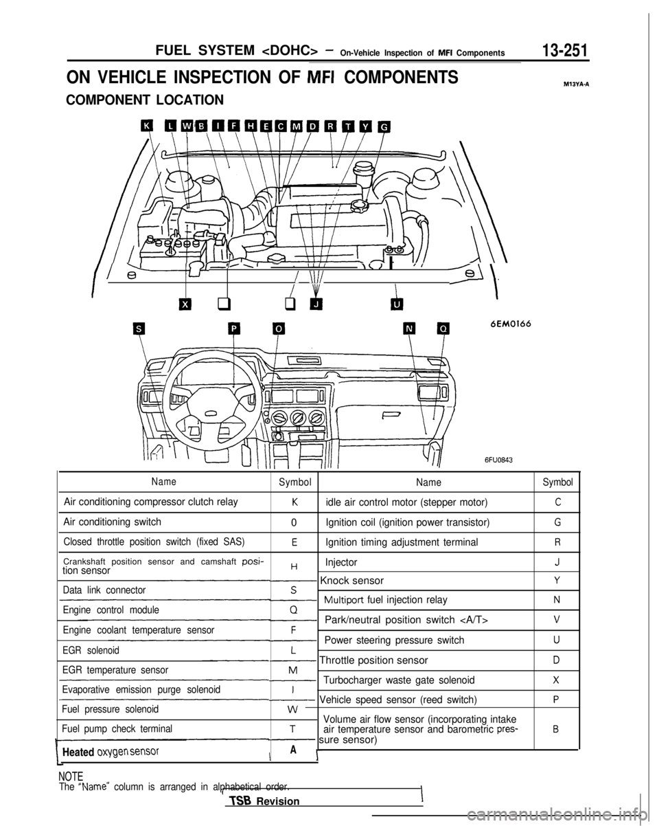
FUEL SYSTEM
ON VEHICLE INSPECTION OF MFI COMPONENTS
COMPONENT LOCATION
4 QCiW41QQWPQWQ
I l-+-Y8’
-,..I- - IIII\< I IJ I
/ \lI/--Gl/
El q
I &
q
‘\
P P
6EM0166
MIBYA-A
6FUO843
NameSymbol
NameSymbol
Air conditioning compressor clutch relayKidle air control motor (stepper motor)C
Air conditioning switch0Ignition coil (ignition power transistor)G
Closed throttle position switch (fixed SAS)EIgnition timing adjustment terminalR
Crankshaft position sensor and camshaft posi-HInjectorJtion sensor- Knock sensorYData link connectorS~Multiport
fuel injection relayNEngine control moduleQ-Park/neutral position switch vEngine coolant temperature sensorF-Power steering pressure switchUEGR solenoidL- Throttle position sensorDEGR temperature sensorM-Turbocharger waste gate solenoidXEvaporative emission purge solenoidI~ Vehicle speed sensor (reed switch)PFuel pressure solenoidwVolume air flow sensor (incorporating intakeFuel pump check terminalTair temperature sensor and barometric pres-B- sure sensor)
Heated
oxygen sensorIA I-
NOTE
The “Name” column is arranged in alphabetical order.II TSB
RevisionI
Page 400 of 1273
k.
13-258FUEL SYSTEM
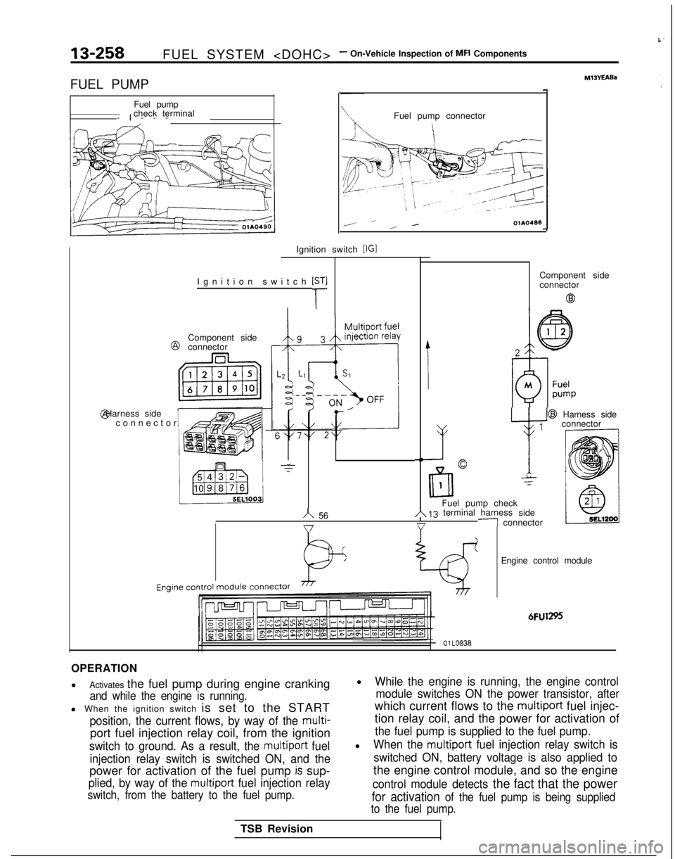
FUEL PUMP Fuel pump
check terminal
-I--
-
Ignition switch
[r
Ignition switch [IGI @
Component side
connector @ Harness side
Iconnecto
r
Fuel pump connector
I
,- __ _ /OlAO488
-T
IComponent side
connector
@
h 56 @
Harness side
1
v y
connector
-NC-
lrll
0
1-z
Fuel pump checkA 13 terminal harness
side-1 connector
I Engine
control
module
connector
Engine control module
6FU1295
01 LO838
OPERATION
l
Activates the fuel pump during engine cranking
and while the engine is running.
l When the ignition switch is set to the START
position, the current flows, by way of the multi-
port fuel injection relay coil, from the ignition
switch to ground. As a result, the multiport fuel
injection relay switch is switched ON, and the
power for activation of the fuel pump is sup-
plied, by way of the multiport fuel injection relay
switch, from the battery to the fuel pump.
lWhile the engine is running, the engine control module switches ON the power transistor, after
which current flows to the multiport fuel injec-
tion relay coil, and the power for activation of
the fuel pump is supplied to the fuel pump.
lWhen the multiport fuel injection relay switch is
switched ON, battery voltage is also applied to
the engine control module, and so the engine
control module detects the fact that the power
for activation of the fuel pump is being supplied
to the fuel pump.
TSB Revision
Page 401 of 1273
FUEL SYSTEM
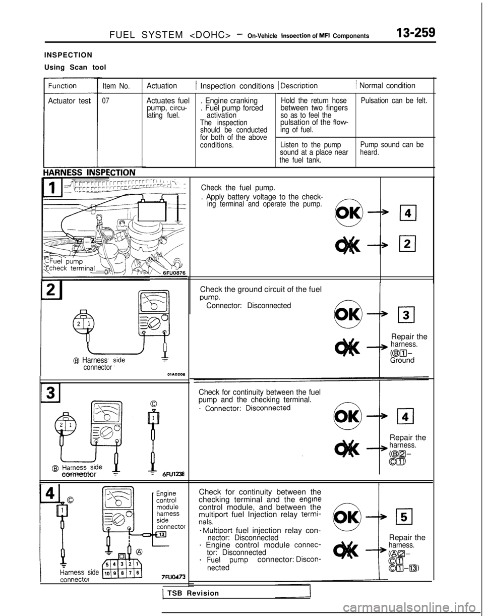
INSPECTION
Using Scan tool
Actuator test
Item No.
07
Actuation1 Inspection conditions 1 Descriotion1 Normal condition
Actuates fuel . Engine cranking
Hold the return hose Pulsation can be felt.pump, circu-. Fuel pump forcedbetween two fingerslating fuel.
activation so as to feel the
The inspectionpulsation of the flow-
should be conducted ing of fuel.
for both of the above
conditions. Listen to the pumpPump sound can be
sound at a place near
heard.the fuel tank.
iCTlON
TGrrW’-rTTrrrrrrrrrrrrrrrrrrri 1 SAL TCheck the fuel pump._---__. Apply battery voltage to the check-ing terminal and operate the pump.
@ Harnessconnector
connector 1
sideI_
Check the ground circuit of the fuel
m-m.Connector: Disconnected
Repair theharness.
if?%d
Check for continuity between the fuel
pump and the checking terminal.
Repair theharness.
CW-
Ml)
Check for continuity between the
checking terminal and the enginecontrol module, and between themultiport fuel Injection relay termi-nals.
* Multiport fuel injection relay con-nector: Disconnected- Engine control module connec-tor: Disconnected
- ;~-:edPumpconnector: Discon-
Repair theharness.
@O-00OIHl3)
1 TSB Revision
Page 402 of 1273
13-260FUEL SYSTEM
!5J
@ Harness srdeconnector
7FUO474
Harness srdc@ connector
Engine control
module harness
side connector
7FUO475
7FUO476
@Harness side
I7FllO477
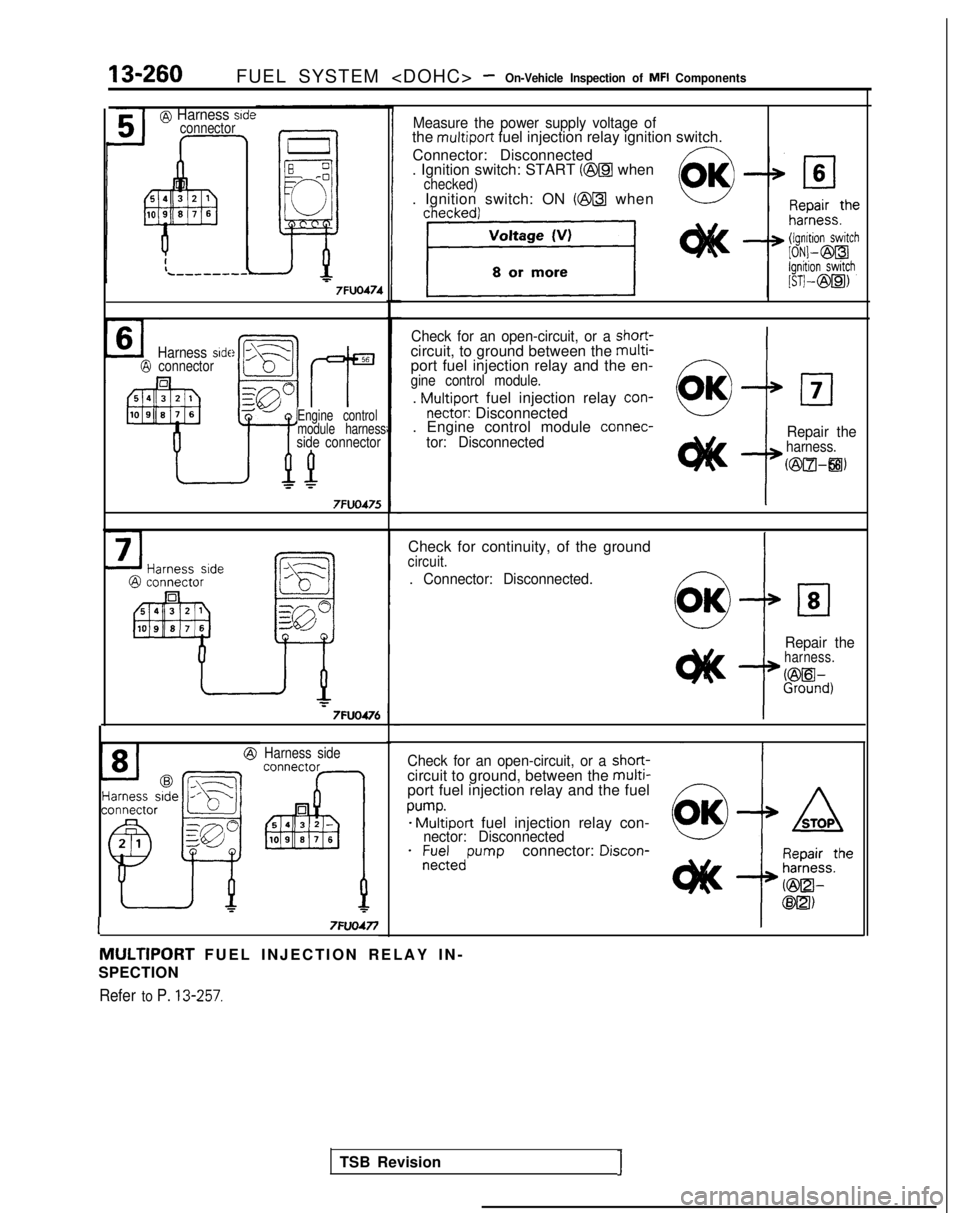
Measure the power supply voltage ofthe multiport fuel injection relay ignition switch.
Connector: Disconnected
. Ignition switch: START
(@a whenchecked). Ignition switch: ON (@@ when
Check for an open-circuit, or a short-circuit, to ground between the multi-port fuel injection relay and the en-gine control module.
. Multiport fuel injection relay con-nectar: Disconnected
. Engine control module connec-
tor: Disconnected Repair the
harness.
uziul-8)
Check for continuity, of the groundcircuit.
. Connector: Disconnected.
cl8
Repair theharness.
%ih,
TSB RevisionJ
Check for an open-circuit, or a short-circuit to ground, between the multi-port fuel injection relay and the fuel
pump.- Multiport fuel injection relay con-nector: Disconnected
- nf;;;edw-wconnector: Discon-
MULTIPORT FUEL INJECTION RELAY IN
-
SPECTION
Refer to P. 13-257.
Page 417 of 1273
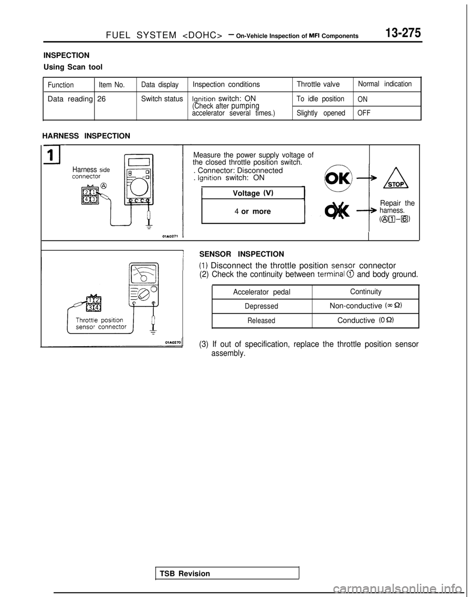
FUEL SYSTEM
INSPECTION
Using Scan tool
Function
Item No.
Data reading 26
Data displayInspection conditions Throttle valveNormal indication
Switch statusIgnition switch: ONTo idle positionON(Check after pumpingaccelerator several times.)
Slightly openedOFF
HARNESS INSPECTION
71
-
Harness side
Measure the power supply voltage of
the closed throttle position switch.
-. Connector: Disconnected
. Ignition switch: ON
1Voltage (VI
4 or more
ASTOP
Repair theharness.
~@a-Q)
ISENSOR INSPECTION
I(1) Disconnect the throttle position senso_r connector
(2) Check the continuity between terminal QI and body ground.
TSB Revision
Accelerator pedal Continuity
DepressedNon-conductive (m S2)
ReleasedConductive (0 52)
(3) If out of specification, replace the throttle position sensor
assembly.
Page 451 of 1273
FUEL SYSTEM
Inspection
of
MFI Components13-309
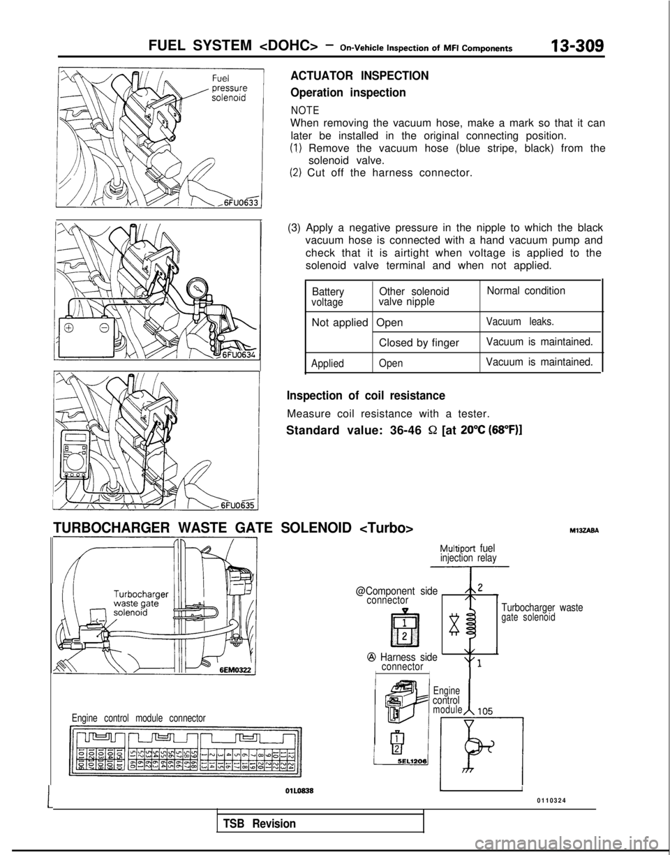
ACTUATOR INSPECTION
Operation inspection
NOTE
When removing the vacuum hose, make a mark so that it can
later be installed in the original connecting position.
(1) Remove the vacuum hose (blue stripe, black) from the solenoid valve.
(2) Cut off the harness connector.
(3) Apply a negative pressure in the nipple to which the black vacuum hose is connected with a hand vacuum pump and
check that it is airtight when voltage is applied to the
solenoid valve terminal and when not applied.
Battery Other solenoid Normal conditionvoltagevalve nipple
Not applied OpenVacuum leaks.
Closed by fingerVacuum is maintained.
Applied
OpenVacuum is maintained.
Inspection of coil resistance
Measure coil resistance with a tester.
Standard value: 36-46
S2 [at 20°C (68”F)I
TURBOCHARGER WASTE GATE SOLENOID
Multiport fuelinjection relay
@Component side,,2
connector/\
1
lE?l283
@J Harness side\/
connector“1
II
Engine control module connector
MlJZABA
Turbocharger wastegate solenoid
Engine
control
1module105
1
OlLo8381I
0110324
TSB Revision
Page 454 of 1273
13-312FUEL SYSTEM
of
MFI
Components
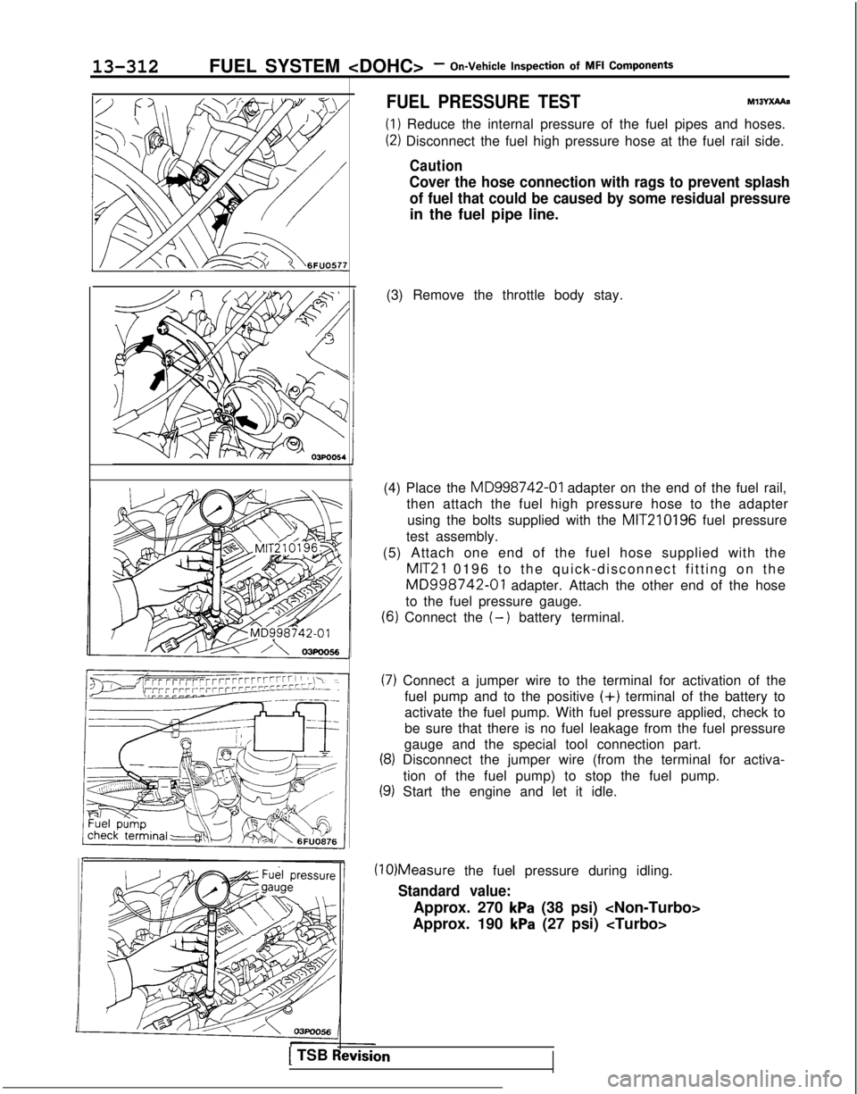
FUEL PRESSURE TESTMxwXAAe
(1) Reduce the internal pressure of the fuel pipes and hoses.
(2) Disconnect the fuel high pressure hose at the fuel rail side.
Caution
Cover the hose connection with rags to prevent splash
of fuel that could be caused by some residual pressure
in the fuel pipe line.
(3) Remove the throttle body stay.
(4) Place the MD998742-01
adapter on the end of the fuel rail,
then attach the fuel high pressure hose to the adapter
using the bolts supplied with the MIT210196
fuel pressure
test assembly.
(5) Attach one end of the fuel hose supplied with the
MIT21 0196 to the quick-disconnect fitting on the
MD998742-01 adapter. Attach the other end of the hose
to the fuel pressure gauge.
(6) Connect the (-) battery terminal.
(7) Connect a jumper wire to the terminal for activation of the fuel pump and to the positive
(+) terminal of the battery to
activate the fuel pump. With fuel pressure applied, check to
be sure that there is no fuel leakage from the fuel pressure
gauge and the special tool connection part.
(8) Disconnect the jumper wire (from the terminal for activa-
tion of the fuel pump) to stop the fuel pump.
(9) Start the engine and let it idle. (10)Measure
the fuel pressure during idling.
Standard value:
Approx. 270 kPa (38 psi)
Approx. 190
kPa (27 psi)
1 TSB Revision
Page 455 of 1273
FUEL SYSTEM
of MFI
Components13-313
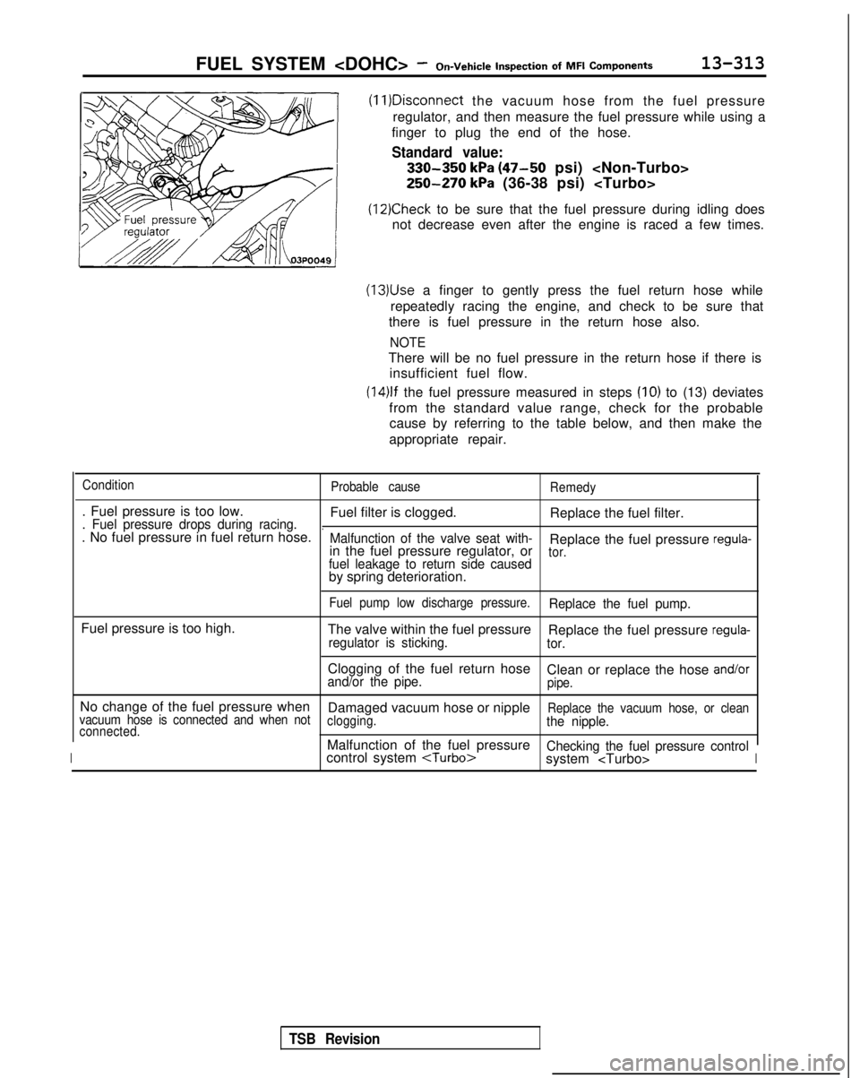
(11)Disconnect
the vacuum hose from the fuel pressure
regulator, and then measure the fuel pressure while using a
finger to plug the end of the hose.
Standard value:
330-350 kPa (47-50 psi)
250-270 kPa (36-38 psi)
(12)Check to be sure that the fuel pressure during idling does
not decrease even after the engine is raced a few times.
(13)Use a finger to gently press the fuel return hose while
repeatedly racing the engine, and check to be sure that
there is fuel pressure in the return hose also.
NOTE
There will be no fuel pressure in the return hose if there is insufficient fuel flow.
(14)lf the fuel pressure measured in steps (IO) to (13) deviates
from the standard value range, check for the probable cause by referring to the table below, and then make the
appropriate repair.
Condition Probable causeRemedy
. Fuel pressure is too low.
Fuel filter is clogged.Replace the fuel filter.. Fuel pressure drops during racing... No fuel pressure in fuel return hose.Malfunction of the valve seat with-Replace the fuel pressure regula-in the fuel pressure regulator, ortor.fuel leakage to return side causedby spring deterioration.
Fuel pump low discharge pressure.Replace the fuel pump.
Fuel pressure is too high.
The valve within the fuel pressureReplace the fuel pressure regula-regulator is sticking. tor.
Clogging of the fuel return hose
Clean or replace the hose and/orand/or the pipe.pipe.
No change of the fuel pressure when Damaged vacuum hose or nippleReplace the vacuum hose, or clean
vacuum hose is connected and when not clogging.the nipple.connected.
IMalfunction of the fuel pressureChecking the fuel pressure controlcontrol system
system
TSB Revision
Page 456 of 1273
13-314FUEL SYSTEM
of
MFI
Components
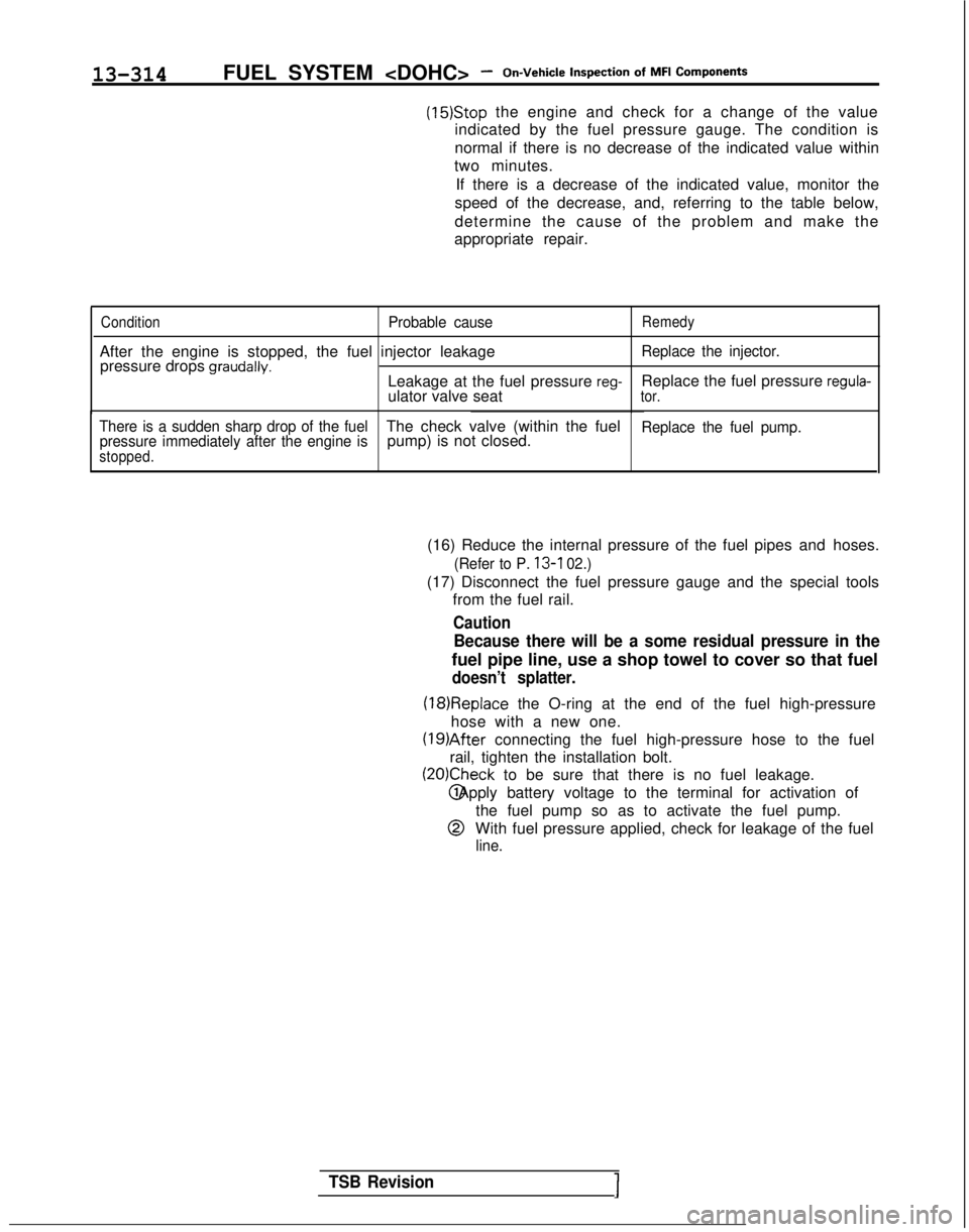
(15)Stop the engine and check for a change of the value
indicated by the fuel pressure gauge. The condition is
normal if there is no decrease of the indicated value within
two minutes.
If there is a decrease of the indicated value, monitor the
speed of the decrease, and, referring to the table below,
determine the cause of the problem and make the
appropriate repair.
ConditionProbable causeRemedy
After the engine is stopped, the fuel injector leakage pressure drops graudally.Replace the injector.
Leakage at the fuel pressure reg-ulator valve seat Replace the fuel pressure regula-tor.
There is a sudden sharp drop of the fuel
pressure immediately after the engine isThe check valve (within the fuel pump) is not closed.Replace the fuel pump.
stopped.
(16) Reduce the internal pressure of the fuel pipes and hoses.
(Refer to P. 13-l 02.)
(17) Disconnect the fuel pressure gauge and the special tools
from the fuel rail.
Caution
Because there will be a some residual pressure in the
fuel pipe line, use a shop towel to cover so that fuel
doesn’t splatter.
(18)Replace the O-ring at the end of the fuel high-pressure
hose with a new one. (19)After
connecting the fuel high-pressure hose to the fuel
rail, tighten the installation bolt.
(20)Check to be sure that there is no fuel leakage. @ Apply battery voltage to the terminal for activation of
@
the fuel pump so as to activate the fuel pump.
With fuel pressure applied, check for leakage of the fuel
line.
TSB Revision1
Page 457 of 1273
FUEL SYSTEM
On-Vehicle
Inwection of MFI
ComDonents13-315
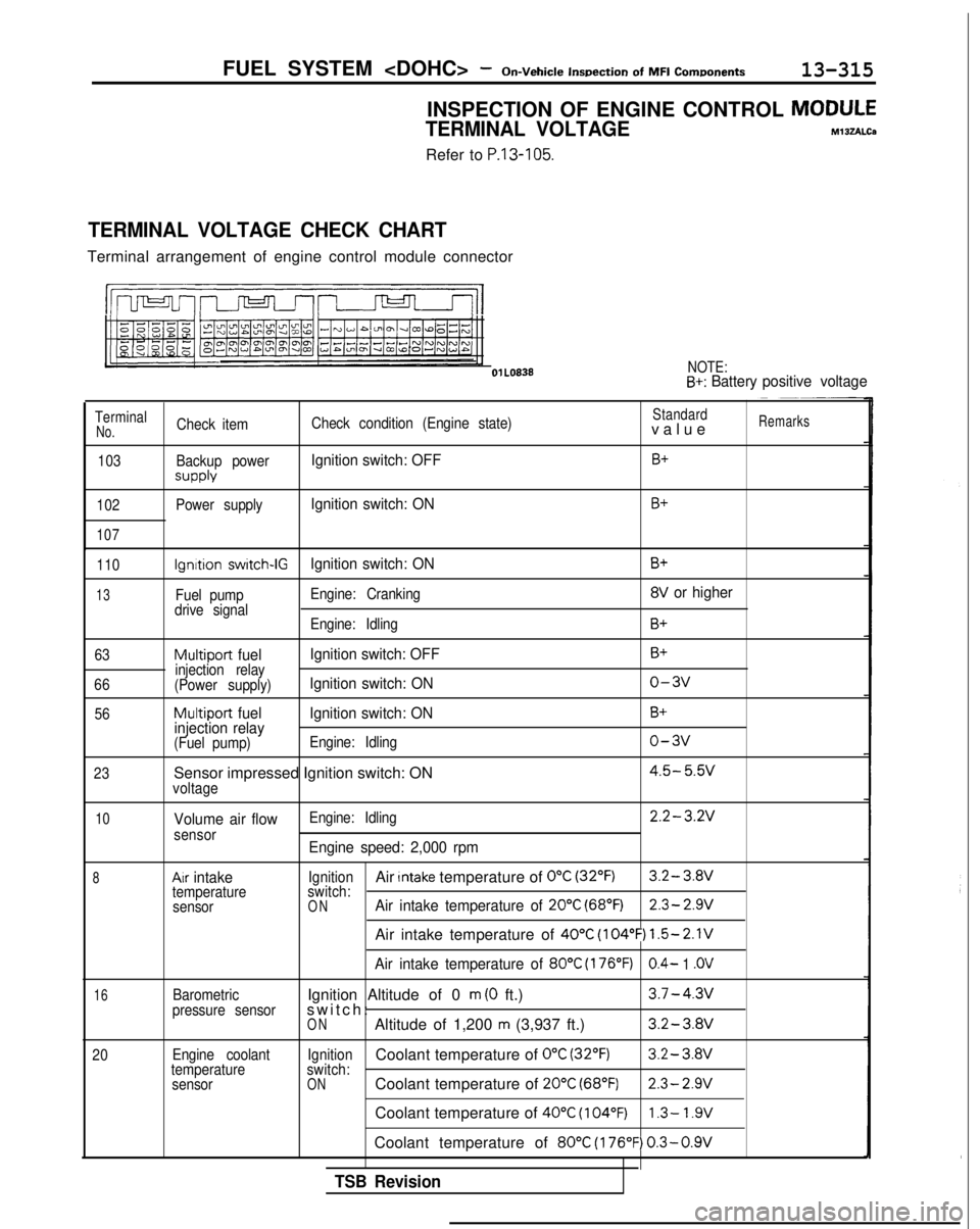
INSPECTION OF ENGINE CONTROL MODULE
TERMINAL VOLTAGEM13zALCa
Refer to P.13-105.
TERMINAL VOLTAGE CHECK CHART
Terminal arrangement of engine control module connector
l!m n-J-J-l-II
NOTE:B+: Battery
positive voltage
TerminalCheck item Check condition (Engine state)Standardvalu
e
Remarks
No.
103
102
107
Backup power
SUPPlY
Power supply
Ignition switch: OFFB+
Ignition switch: ONB+
110
13
63
66 56
23
Ignition switch-IGIgnition switch: ON
Fuel pump Engine: Cranking
drive signal Engine: Idling
Multiport fuel Ignition switch: OFFinjection relay
(Power supply)Ignition switch: ON
Multiport fuel Ignition switch: ON
injection relay
(Fuel pump) Engine: Idling
Sensor impressed Ignition switch: ONvoltage
B+
8V or higher
B+
B+
o-3v
B+
o-3v
4.5- 5.w
10
8
16
20
Volume air flowsensor
Ax intaketemperature
sensor
Barometric
pressure sensor
Engine coolant
temperature sensor Engine: Idling
2.2-3.2V
Engine speed: 2,000 rpm
IgnitionAir Intake temperature of 0°C (32°F)3.2- 3.8V
switch:
ONAir intake temperature of 20°C (68°F)2.3- 2.9V
Air intake temperature of 40°C (104°F) 1.5-2.1V
Air intake temperature of 80°C (176°F)0.4- 1 .OV
Ignition Altitude of 0 m (0 ft.)3.7-4.3v
switch
:
ONAltitude of 1,200 m (3,937 ft.)3.2-3.8V
IgnitionCoolant temperature of 0°C (32’F)3.2-
3.Wswitch:ONCoolant temperature of 20°C (68°F)2.3- 2.9V
Coolant temperature of 40°C (104°F)1.3- 1.9V
Coolant temperature of 80°C (176°F) 0.3-0.9V
TSB Revision