alarm MITSUBISHI GALANT 1989 Service Repair Manual
[x] Cancel search | Manufacturer: MITSUBISHI, Model Year: 1989, Model line: GALANT, Model: MITSUBISHI GALANT 1989Pages: 1273, PDF Size: 37.62 MB
Page 940 of 1273
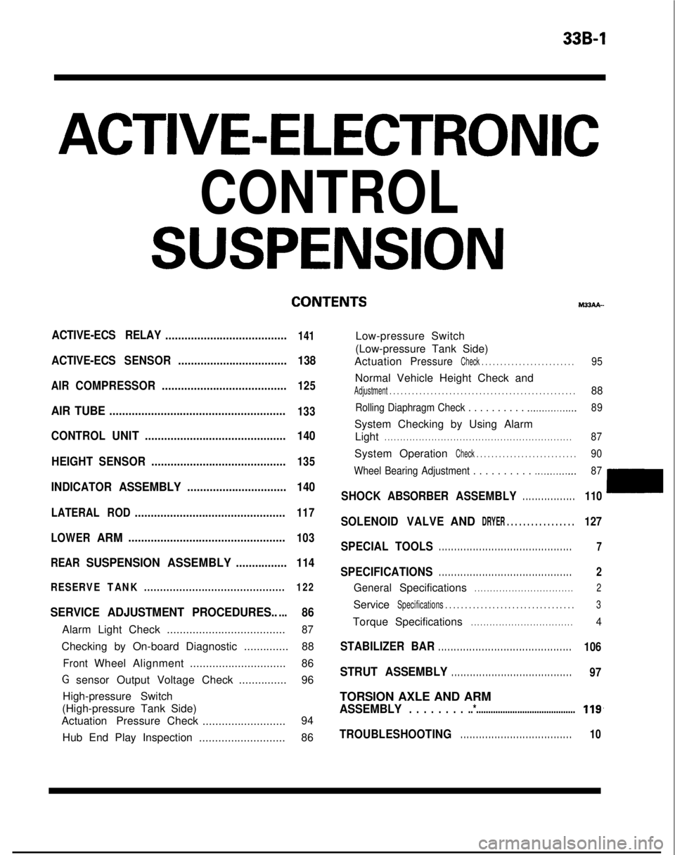
339-l
ACTIVE-ELECTRONIC
CONTROL
SUSPENSION
ACTIVE-ECS RELAY......................................141
ACTIVE-ECSSENSOR.................................. 138
AIRCOMPRESSOR.......................................125
AIR TUBE.......................................................133
CONTROLUNIT............................................ 140
HEIGHT SENSOR ..........................................
135
INDICATORASSEMBLY............................... 140
LATERALROD...............................................117
LOWER
ARM.................................................103
REAR
SUSPENSION ASSEMBLY................114
RESERVETANK............................................ 122
SERVICE ADJUSTMENT PROCEDURES.....86
Alarm Light Check.....................................87
Checking by On-board Diagnostic ..............88
FrontWheelAlignment .............................. 86
G sensor Output Voltage Check ...............96
High-pressure Switch
(High-pressure Tank Side)
Actuation Pressure Check
.......................... 94
Hub End Play Inspection ...........................86 M33AA-
Low-pressure Switch
(Low-pressure Tank Side)
Actuation
PressureCheck . . . . . . . . . . . . . . . . . . . . . . . . .95
Normal Vehicle Height Check and
Adjustment . . . . . . . . . . . . . . . . . . . . . . . . . . . . . . .\
. . . . . . . . . . . . . . . . . . .88
Rolling Diaphragm Check . . . . . . . . . . .._.............. 89
System Checking by Using Alarm
Light
. . . . . . . . . . . . . . . . . . . . . . . . . . . . . . . . . . . . \
. . . . . . . . . . . . . . . . . . . . . . . .87
System OperationCheck . . . . . . . . . . . . . . . . . . . . . . . . . . .90
Wheel Bearing Adjustment . . . . . . . . . .
.._........... 87
SHOCKABSORBER ASSEMBLY. . . . . . . . . . . . . . . . .110
SOLENOIDVALVEANDDRYER . . . . . . . . . . . . . . . . .127
SPECIAL TOOLS. . . . . . . . . . . . . . . . . . . . . . . . . . . . . . . . . . . . \
. . . . . . .7
SPECIFICATIONS. . . . . . . . . . . . . . . . . . . . . . . . . . . . . . . . . . . . \
. . . . . . .2
GeneralSpecifications. . . . . . . . . . . . . . . . . . . . . . . . . . . . . . . .2
ServiceSpecifications . . . . . . . . . . . . . . . . . . . . . . . . . . . . .\
. . . .3
TorqueSpecifications. . . . . . . . . . . . . . . . . . . . . . . . . . . . . . . . .4
STABILIZER BAR. . . . . . . . . . . . . . . . . . . . . . . . . . . . . . . . . . . . \
. . . . . . .106
STRUT ASSEMBLY. . . . . . . . . . . . . . . . . . . . . . . . . . . . . . . . . . . . \
. . .97
TORSION AXLE AND ARM
ASSEMBLY. . . . . . . . ..*.........................................119,
TROUBLESHOOTING. . . . . . . . . . . . . . . . . . . . . . . . . . . . . . . . . . . .10
Page 950 of 1273
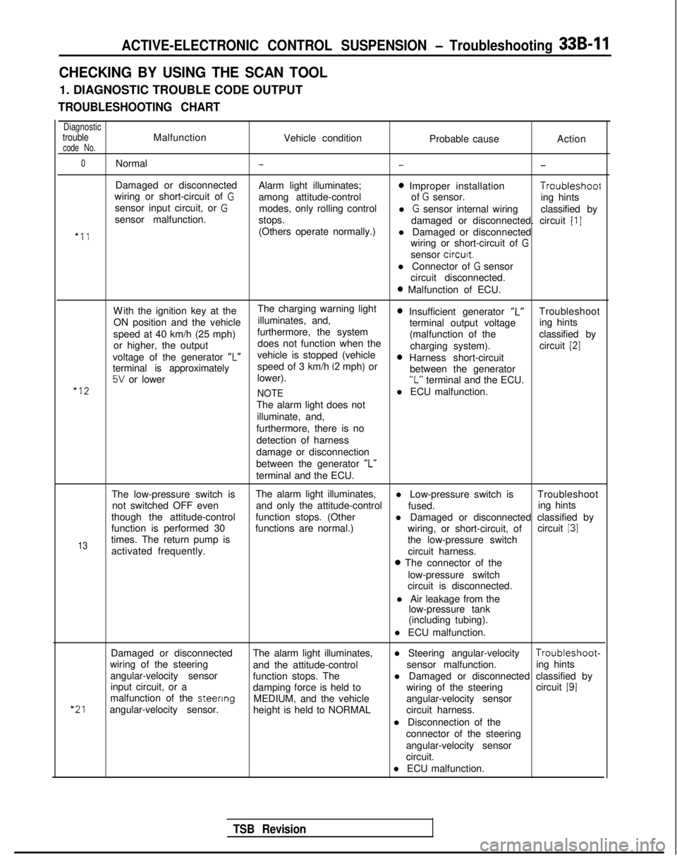
ACTIVE-ELECTRONIC CONTROL SUSPENSION - Troubleshooting 33B-11
CHECKING BY USING THE SCAN TOOL
1. DIAGNOSTIC TROUBLE CODE OUTPUT
TROUBLESHOOTING CHART
DiagnostictroubleMalfunctionVehicle conditioncode No.Probable causeAction
0Normal---
Damaged or disconnected
Alarm light illuminates;0 Improper installation Troubleshoof
wiring or short-circuit of Gamong attitude-control of G sensor.
sensor input circuit, or Ging hints
modes, only rolling control
sensor malfunction. l
G sensor internal wiring
classified by
stops. damaged or disconnected. circuit
[I]
“11(Others operate normally.)l Damaged or disconnected
wiring or short-circuit of
G
sensor circurt.
l Connector of
G sensor
circuit disconnected.
0 Malfunction of ECU.
W
ith the ignition key at the
The charging warning light
ON position and the vehicle illuminates, and,
0 Insufficient generator “L”Troubleshoot
speed at 40 km/h (25 mph) furthermore, the system terminal output voltage
ing hints
or higher, the output does not function when the (malfunction of the
classified by
charging system). circuit
[2]
voltage of the generator ‘I”vehicle is stopped (vehicle0 Harness short-circuit
terminal is approximately speed of 3 km/h (2 mph) or
5V or lower
lower). between the generator“L” terminal and the ECU.“12
NOTEl ECU malfunction.
The alarm light does not illuminate, and,
furthermore, there is no
detection of harness
damage or disconnection
between the generator “L”
terminal and the ECU.
The low-pressure switch is The alarm light illuminates,
l Low-pressure switch is Troubleshoot
not switched OFF even and only the attitude-control
fused.
though the attitude-control ing hints
function stops. (Other l Damaged or disconnected classified by
function is performed 30 functions are normal.) circuit
131
13times. The return pump is wiring, or short-circuit, of
the low-pressure switch
activated frequently. circuit harness.
0 The connector of the
low-pressure switch
circuit is disconnected.
l Air leakage from the low-pressure tank
(including tubing).
l ECU malfunction.
“21
Damaged or disconnected The alarm light illuminates,l Steering angular-velocity Troubleshoot-
wiring of the steering and the attitude-control sensor malfunction.
angular-velocity sensor ing hints
function stops. The
input circuit, or a l Damaged or disconnected classified by
damping force is held to wiring of the steeringcircuit
191malfunction of the steenng
MEDIUM, and the vehicle
angular-velocity sensor. angular-velocity sensor
height is held to NORMAL circuit harness.
l Disconnection of the connector of the steering
angular-velocity sensor
circuit.
l ECU malfunction.
TSB Revision
Page 951 of 1273
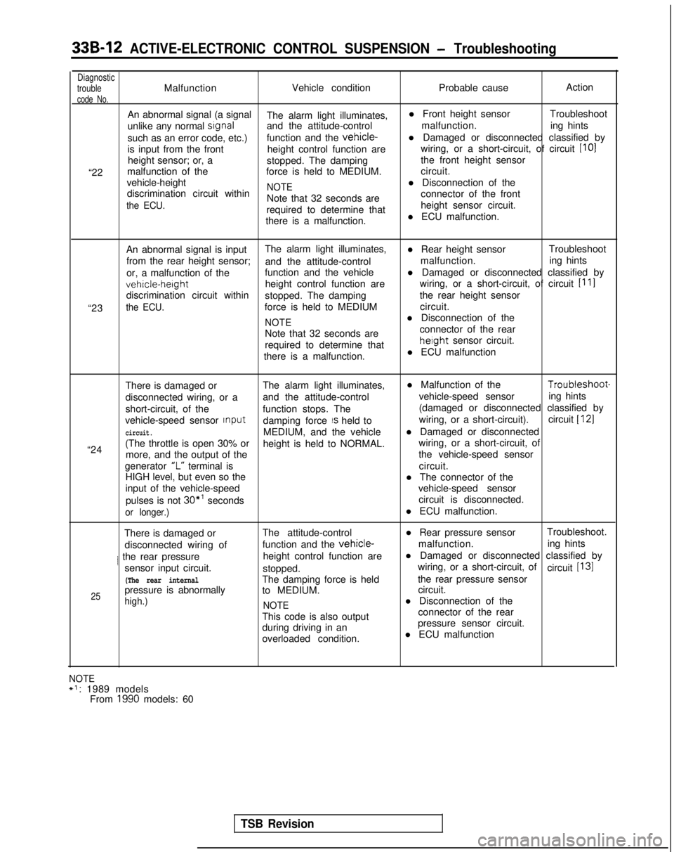
33B-12 ACTIVE-ELECTRONIC CONTROL SUSPENSION - Troubleshooting
Diagnostic
troubleMalfunction Vehicle condition
Probable causeAction
code No.
An abnormal signal (a signal
The alarm light illuminates, l Front height sensor
Troubleshoot
unlike any normal
srgnaland the attitude-control malfunction.
ing hints
such as an error code, etc.) function and the
vehicle-l Damaged or disconnected classified by
is input from the front height control function are wiring, or a short-circuit, of circuit [IO]
height sensor; or, a stopped. The damping the front height sensor
“22 malfunction of the
force is held to MEDIUM. circuit.
vehicle-height
NOTEl Disconnection of the
discrimination circuit within
the ECU.Note that 32 seconds are connector of the front
required to determine that height sensor circuit.
there is a malfunction. l ECU malfunction.
“23 An abnormal signal is input
The alarm light illuminates,
l Rear height sensorTroubleshoot
from the rear height sensor; and the attitude-control malfunction.
ing hints
or, a malfunction of the function and the vehicle
l Damaged or disconnected classified byvehicle-height
height control function are
wiring, or a short-circuit, of circuit
[I 11
discrimination circuit within
stopped. The damping the rear height sensor
the ECU.force is held to MEDIUM circuit.
NOTEl Disconnection of the
Note that 32 seconds are connector of the rear
required to determine that
height sensor circuit.
there is a malfunction. l ECU malfunction
There is damaged or The alarm light illuminates, l Malfunction of the Troubleshoot-
disconnected wiring, or a and the attitude-control vehicle-speed sensor
ing hints
short-circuit, of the function stops. The (damaged or disconnected classified by
vehicle-speed sensor Input
damping force
IS held to wiring, or a short-circuit).
circuit [ 121
circuit.MEDIUM, and the vehicle l Damaged or disconnected
“24 (The throttle is open 30% or
height is held to NORMAL. wiring, or a short-circuit, of
more, and the output of the the vehicle-speed sensor
generator “L”
terminal is circuit.
HIGH level, but even so the l The connector of the
input of the vehicle-speed vehicle-speed sensor
pulses is not
30*’ seconds circuit is disconnected.
or longer.)l ECU malfunction.
There is damaged or The attitude-control
l Rear pressure sensorTroubleshoot.
disconnected wiring of function and the
vehicle-malfunction.
ing hints
/ the rear pressure height control function arel Damaged or disconnected classified by
sensor input circuit. stopped. wiring, or a short-circuit, of
circuit
[I31
(The rear internalThe damping force is held the rear pressure sensor
25pressure is abnormally
to MEDIUM. circuit.
high.)
NOTEl Disconnection of the
This code is also output connector of the rear
during driving in an pressure sensor circuit.
overloaded condition. l ECU malfunction
NOTE+1: 1989 models
From 1990 models: 60
TSB Revision
Page 952 of 1273
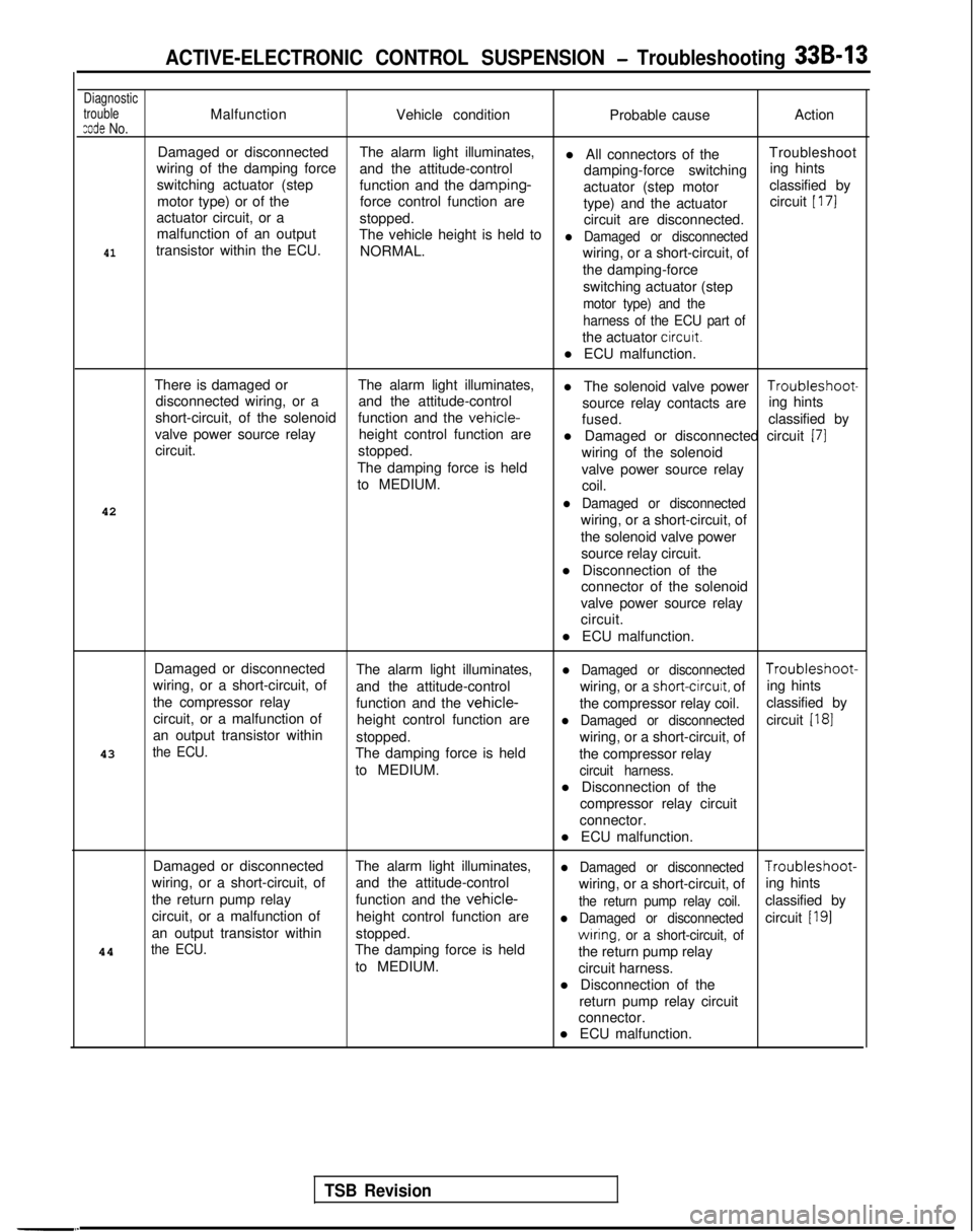
ACTIVE-ELECTRONIC CONTROL SUSPENSION - Troubleshooting 33B-13
Diagnostic
trouble
zode No.MalfunctionVehicle condition Probable causeAction
Damaged or disconnected The alarm light illuminates,
l All connectors of theTroubleshoot
wiring of the damping force and the attitude-control
damping-force switchinging hints
switching actuator (step function and the damping-
actuator (step motor classified by
motor type) or of the force control function are
type) and the actuatorcircuit
[ 171
actuator circuit, or a
stopped.
circuit are disconnected.
malfunction of an output The vehicle height is held to
l Damaged or disconnected41transistor within the ECU. NORMAL.
wiring, or a short-circuit, of
the damping-force
switching actuator (step
motor type) and the
harness of the ECU part of
the actuator circutt.
l ECU malfunction.
There is damaged or The alarm light illuminates,
l The solenoid valve power Troubleshoot-
disconnected wiring, or a and the attitude-control
short-circuit, of the solenoid source relay contacts are
ing hints
function and the
vehicle-fused. classified by
valve power source relay height control function are
circuit. l Damaged or disconnected circuit
(71stopped.
wiring of the solenoid
The damping force is held valve power source relay
to MEDIUM. coil.
42
l Damaged or disconnected
wiring, or a short-circuit, of
the solenoid valve power source relay circuit.
l Disconnection of the connector of the solenoid
valve power source relay
circuit.
l ECU malfunction.
Damaged or disconnected The alarm light illuminates,
l Damaged or disconnected Troubleshoot-
wiring, or a short-circuit, of and the attitude-control wiring, or a
short-circuit, ofing hints
the compressor relay function and the
vehicle-the compressor relay coil.classified by
circuit, or a malfunction of height control function are
l Damaged or disconnectedcircuit [I81an output transistor within
stopped.
43
the ECU.wiring, or a short-circuit, of
The damping force is held the compressor relay
to MEDIUM.
circuit harness.
l Disconnection of the
compressor relay circuit
connector.
l ECU malfunction.
Damaged or disconnected The alarm light illuminates,
l Damaged or disconnected Troubleshoot-
wiring, or a short-circuit, of and the attitude-control
wiring, or a short-circuit, ofing hints
the return pump relay function and the
vehicle-the return pump relay coil.classified by
circuit, or a malfunction of height control function are
l Damaged or disconnectedcircuit [I91an output transistor withinstopped.
the ECU.The damping force is heldwrring, or a short-circuit, of44
the return pump relay
to MEDIUM. circuit harness.
l Disconnection of the return pump relay circuit
connector.
l ECU malfunction.
TSB Revision
Page 953 of 1273
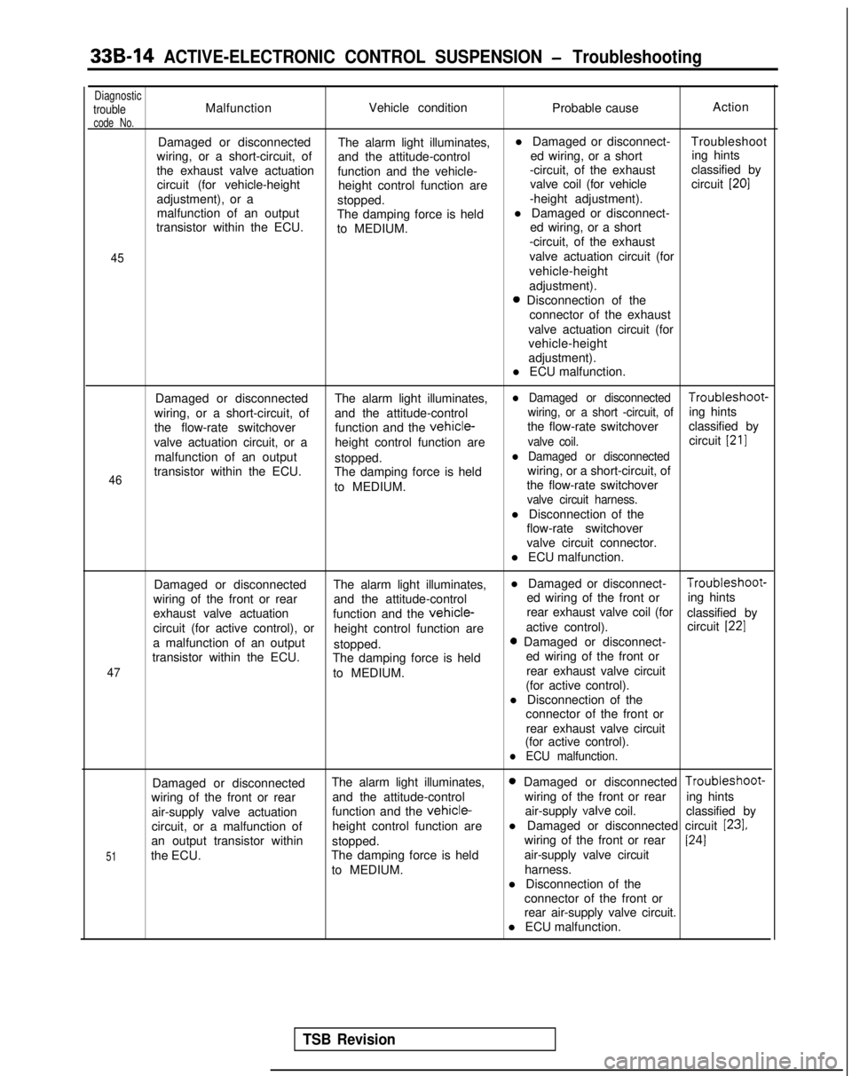
33B-14 ACTIVE-ELECTRONIC CONTROL SUSPENSION - Troubleshooting
DiagnostictroubleMalfunctionVehicle condition
Probable causeAction
code No.
Damaged or disconnected
The alarm light illuminates,l Damaged or disconnect-
Troubleshoot
wiring, or a short-circuit, of and the attitude-control ed wiring, or a shorting hints
the exhaust valve actuation function and the vehicle- -circuit, of the exhaust
classified by
circuit (for vehicle-height height control function are valve coil (for vehicle
circuit
[20]
adjustment), or a
stopped. -height adjustment).
malfunction of an output The damping force is heldl Damaged or disconnect-
transistor within the ECU. to MEDIUM. ed wiring, or a short
-circuit, of the exhaust
45valve actuation circuit (for
vehicle-height
adjustment).
0 Disconnection of the connector of the exhaust
valve actuation circuit (for
vehicle-height
adjustment).
l ECU malfunction.
46
Damaged or disconnected The alarm light illuminates,l Damaged or disconnected Troubleshoot-
wiring, or a short-circuit, of and the attitude-control
wiring, or a short -circuit, ofing hints
the flow-rate switchover function and the
vehicle-the flow-rate switchoverclassified by
valve actuation circuit, or a height control function are
valve coil.circuit [21]
malfunction of an output
stopped.l Damaged or disconnected
transistor within the ECU. The damping force is held wiring, or a short-circuit, of
to MEDIUM. the flow-rate switchover
valve circuit harness.
l Disconnection of the
flow-rate switchover
valve circuit connector.
l ECU malfunction.
47
Damaged or disconnected The alarm light illuminates,l Damaged or disconnect- Troubleshoot-
wiring of the front or rear and the attitude-control ed wiring of the front or
ing hints
exhaust valve actuation function and the
vehicle-rear exhaust valve coil (for
classified by
circuit (for active control), or height control function are active control).
circuit
[22]
a malfunction of an output
stopped.0 Damaged or disconnect-
transistor within the ECU. The damping force is held ed wiring of the front or
to MEDIUM. rear exhaust valve circuit
(for active control).
l Disconnection of the connector of the front or
rear exhaust valve circuit
(for active control).
l ECU malfunction.
51
Damaged or disconnected The alarm light illuminates,0 Damaged or disconnected Troubleshoot-
wiring of the front or rear and the attitude-control wiring of the front or rear
ing hints
air-supply valve actuation function and the
vehicle-air-supply valve
coil. classified by
circuit, or a malfunction of height control function arel Damaged or disconnected circuit
[23],
an output transistor within
stopped. wiring of the front or rear1241
the ECU.
The damping force is held air-supply valve circuit
to MEDIUM. harness.
l Disconnection of the connector of the front or
rear air-supply valve circuit.
l ECU malfunction.
TSB Revision
Page 954 of 1273
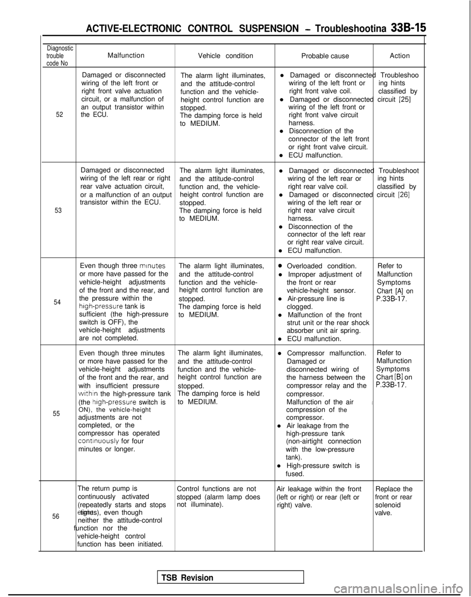
ACTIVE-ELECTRONIC CONTROL SUSPENSION - Troubleshootina 33B-15
Diagnostic
trouble
code NoMalfunction Vehicle condition Probable causeAction
52
Damaged or disconnected
The alarm light illuminates, l Damaged or disconnected Troubleshoo
wiring of the left front or and the attitude-control wiring of the left front or
ing hints
right front valve actuation function and the vehicle- right front valve coil.
classified by
circuit, or a malfunction of height control function arel Damaged or disconnected circuit
[25]an output transistor within
stopped. wiring of the left front orthe ECU.The damping force is held
right front valve circuit
to MEDIUM. harness.
l Disconnection of the connector of the left front
or right front valve circuit.
l ECU malfunction.
53
Damaged or disconnected The alarm light illuminates,
wiring of the left rear or right l Damaged or disconnected Troubleshoot
and the attitude-control wiring of the left rear or
rear valve actuation circuit, ing hints
function and, the vehicle- right rear valve coil.
classified by
or a malfunction of an output height control function are
transistor within the ECU. l Damaged or disconnected circuit
[26]
stopped.
wiring of the left rear or
The damping force is held right rear valve circuit
to MEDIUM.
harness.
l Disconnection of the connector of the left rear
or right rear valve circuit.
l ECU malfunction.
54
55
Even though three mrnutes
The alarm light illuminates,0 Overloaded condition. Refer to
or more have passed for the and the attitude-control l Improper adjustment ofMalfunction
vehicle-height adjustments function and the vehicle- the front or rear
of the front and the rear, and Symptoms
height control function are vehicle-height sensor.
Chart [A] onthe pressure within thestopped.l Air-pressure line isP.33B-17.high-pressure
tank is
The damping force is held
sufficient (the high-pressure clogged.
to MEDIUM. l Malfunction of the front
switch is OFF), the strut unit or the rear shock
vehicle-height adjustments absorber unit air spring.
are not completed. l ECU malfunction.
Even though three minutes The alarm light illuminates,
l Compressor malfunction.Refer to
or more have passed for the and the attitude-control Damaged orMalfunction
vehicle-height adjustments function and the vehicle- disconnected wiring ofSymptoms
of the front and the rear, and height control function are
the harness between theChart
LB1 on
with insufficient pressure stopped. compressor relay and the
P.33B-17.
withtn the high-pressure tankThe damping force is held
compressor.
(the high-pressure
switch isto MEDIUM.
Malfunction of the air
iON), the vehicle-height compression of the
adjustments are not compressor.
completed, or the l Air leakage from the
compressor has operated
continuously for four high-pressure tank
minutes or longer. (non-airtight connection
with the low-pressure
tank).
l High-pressure switch is fused.
The return pump is Control functions are not Air leakage within the frontReplace the
continuously activated stopped (alarm lamp does (left or right) or rear (left orfront or rear
(repeatedly starts and stops not illuminate).
right) valve.solenoid
56erght times), even though
valve.
neither the attitude-control
function nor the
vehicle-height control
function has been initiated.
TSB Revision
Page 955 of 1273
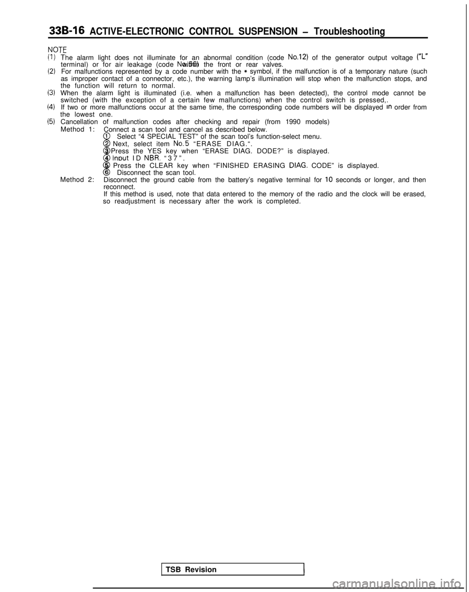
33B-16 ACTIVE-ELECTRONIC CONTROL SUSPENSION - Troubleshooting
NOT’=
(1)
(2)
13)
(4)
(5)
‘T‘he alarm light does not illuminate for an abnormal condition (code No.12) of the generator output voltage (#,.terminal) or for air leakage (code No.56) within the front or rear valves.
For malfunctions represented by a code number with the* symbol, if the malfunction is of a temporary nature (such
as improper contact of a connector, etc.), the warning lamp’s illumi\
nation will stop when the malfunction stops, and
the function will return to normal.
When the alarm light is illuminated (i.e. when a malfunction has been d\
etected), the control mode cannot be switched (with the exception of a certain few malfunctions) when the c\
ontrol switch is pressed,.
If two or more malfunctions occur at the same time, the corresponding co\
de numbers will be displayed
In order from
the lowest one.
Cancellation of malfunction codes after checking and repair (from 1990 \
models)
Method 1: Connect a scan tool and cancel as described below.
1
w
Select “4 SPECIAL TEST” of the scan tool’s function-select menu\
.2 Next, select item No.5
“ERASE DIAG.“.
3 Press the YES key when “ERASE DIAG. DODE?” is displayed.
4
lnout ID NBR. “37”
.
8
5 Press the CLEAR key when “FINISHED ERASING DIAG. CODE” is displayed.6Disconnect the scan tool.
Method 2: Disconnect the ground cable from the battery’s negative terminal for \
10 seconds or longer, and then
reconnect.
If this method is used, note that data entered to the memory of the radi\
o and the clock will be erased,
so readjustment is necessary after the work is completed.
TSB Revision
1
Page 962 of 1273
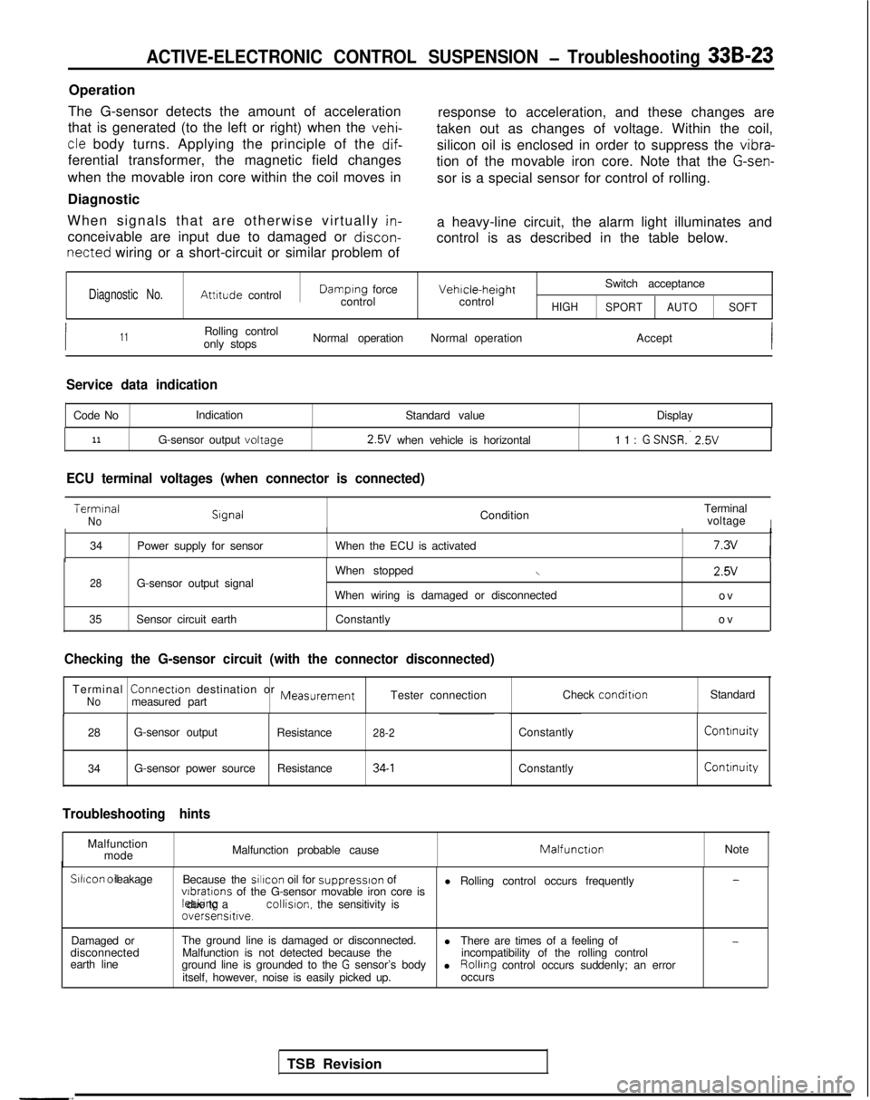
ACTIVE-ELECTRONIC CONTROL SUSPENSION - Troubleshooting 33B-23
Operation
The G-sensor detects the amount of acceleration
that is generated (to the left or right) when the
vehi-
response to acceleration, and these changes are
cle body turns. Applying the principle of the dif-
taken out as changes of voltage. Within the coil,
ferential transformer, the magnetic field changes silicon oil is enclosed in order to suppress the vibra-
tion of the movable iron core. Note that the
G-sen-
when the movable iron core within the coil moves in
Diagnostic sor is a special sensor for control of rolling.
When signals that are otherwise virtually
in-
conceivable are input due to damaged or discon-
a heavy-line circuit, the alarm light illuminates and
control is as described in the table below.
netted wiring or a short-circuit or similar problem of
Diagnostic No.Attitude controlDamplng force
controlVehicle-heightcontrol Switch acceptanceHIGH
SPORT AUTO SOFT
I11Rolling control
only stops Normal operation
Normal operation Accept
Service data indication
Code NoIndication
Standard value Display
11G-sensor output voltage 2.5V
when vehicle is horizontal 11: G SNSR:
2.5V
ECU terminal voltages (when connector is connected)
Terminal
NoCondition
Terminal
voltageIII
34 Power supply for sensor When the ECU is activated7.3vI
28G-sensor output signal
35 Sensor circuit earth When stoppedi
When wiring is damaged or disconnected
Constantly 2.5V
ov
ov
TSB Revision
-.
Checking the G-sensor circuit (with the connector disconnected)
Terminal ConnectIon
destination or MeasurementNomeasured part Tester connection
Check conditionStandard
28 G-sensor output
Resistance
28-2ConstantlyContinuity
34G-sensor power source
Resistance34-1ConstantlyContinuity
Troubleshooting hints
Malfunction
mode Malfunction probable causeMatfunctIonNoteSilicon
oil leakage
Because the sillcon
oil for
suppresslon of
l Rolling control occurs frequently-
vlbratlons of the G-sensor movable iron core is leaktng due to a collision.
the sensitivity is
oversensitive.
Damaged or
disconnected
earth line The ground line is damaged or disconnected.
l-Malfunction is not detected because the There are times of a feeling of
ground line is grounded to the G sensor’s body incompatibility of the rolling control
l
itself, however, noise is easily picked up. Rolling
control occurs suddenly; an error
occurs
Page 964 of 1273
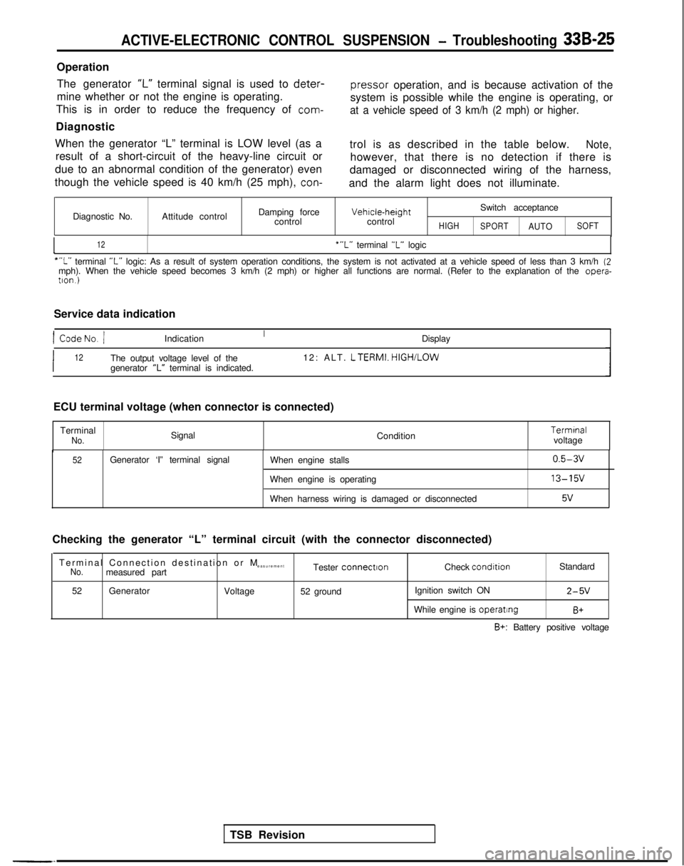
ACTIVE-ELECTRONIC CONTROL SUSPENSION - Troubleshooting 33B-25
OperationThe generator
‘I-” terminal signal is used to deter-
pressor
operation, and is because activation of the
mine whether or not the engine is operating.
This is in order to reduce the frequency of
com-
system is possible while the engine is operating, or
at a vehicle speed of 3 km/h (2 mph) or higher.
Diagnostic
When the generator “L” terminal is LOW level (as a result of a short-circuit of the heavy-line circuit or
due to an abnormal condition of the generator) even
though the vehicle speed is 40 km/h (25 mph),
con-
trol is as described in the table below.Note,
however, that there is no detection if there is
damaged or disconnected wiring of the harness,
and the alarm light does not illuminate.
Diagnostic No. Attitude control Damping force
control Vehrcle-height
control
HIGH
Switch acceptance
SPORTAUTOSOFT
I12‘“L” terminal “L” logic
““L” terminal “L” logic: As a result of system operation conditions, the system is not ac\
tivated at a vehicle speed of less than 3 km/h (2mph). When the vehicle speed becomes 3 km/h (2 mph) or higher all fun\
ctions are normal. (Refer to the explanation of the opera-
tron.)
Service data indication
1 CodeNo. /Indication Display
I12The output voltage level of the12: ALT. LTERMI.
HIGH/LOW
generator “L” terminal is indicated.
TSB Revision
ECU terminal voltage (when connector is connected)
Terminal
No.Signal Condition Termrnal
voltage
52Generator ‘I” terminal signal When engine stalls
When engine is operating
When harness wiring is damaged or disconnected0.5-3v
13-15v
5v
Checking the generator “L” terminal circuit (with the connector d\
isconnected)
Terminal Connection destination or
M
easurement
No.measured part Tester connectronCheck condrtion
Standard
52 Generator
Voltage52 ground Ignition switch ON
2-5V
While engine is operatingB+
B+: Battery positive voltage
Page 966 of 1273
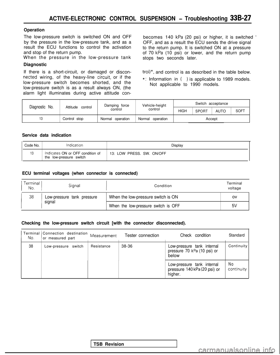
ACTIVE-ELECTRONIC CONTROL SUSPENSION - Troubleshooting 33B-27
Operation
The low-pressure switch is switched ON and OFFby the pressure in the low-pressure tank, and as a becomes 140 kPa (20 psi) or higher, it is switched *
result the ECU functions to control the activation
OFF, and as a result the ECU sends the drive signal
and stop of the return pump. to the return pump. It is switched ON at a pressure
When the pressure in the low-pressure tank of 70
kPa (10 psi) or lower, and the return pump
stops two seconds later.
Diagnostic
If there is a short-circuit, or damaged or discon-
netted wiring, of the heavy-line
circuit,
or if the
low-pressure switch becomes shorted, and the low-pressure switch is as a result always ON, (the
trol)“, and control is as described in the table below.
alarm light illuminates during active attitude
con-
*: Information in () is applicable to 1989 models.
Not applicable to 1990 models.
Diagnostic No.Attitude control Damping force
Vehicle-height Switch acceptance
control controlHIGH
SPORTAUTOSOFT
13Control stop Normal operationNormal operation Accept
Service data indication
Code No.lndicatron
Display
13Indicates
ON or OFF condition of
13: LOW PRESS. SW. ON/OFF
the low-pressure switch
ECU terminal voltages (when connector is connected)
TSB Revision
/ Te;;,nal 1Condition Terminal
voltage
Low-pressure tank pressure
signalWhen the low-pressure switch is ONov
When the low-pressure switch is OFF5v
Checking the low-pressure switch circuit [with the connector disconnecte\
d).
I No.
Terminal Connection destination Measurement
!or measured partTester connectionCheck conditionStandard
38Low-pressure switch Resistance
38-36Low-pressure tank internalContinuit
y
pressure 70 kPa (10 psi) or
below
Low-pressure tank internalNo
pressure 140 kPa (20 psi) orcontinuity
higher.