rims MITSUBISHI GALANT 1989 Service Repair Manual
[x] Cancel search | Manufacturer: MITSUBISHI, Model Year: 1989, Model line: GALANT, Model: MITSUBISHI GALANT 1989Pages: 1273, PDF Size: 37.62 MB
Page 1053 of 1273
33B-114 ACTIVE-ELECTRONIC CONTROL SUSPENSION - ~:h%pension
REAR SUSPENSION ASSEMBLYM33GA-A
REMOVAL AND INSTALLATION
50-60 Nm
17-26 Nm 36-43 ftlbs.
12-19
ft.lbs. 2
,
9-14
‘Nm7-10 ftlbs.
Vehicles with A.B.S. 9-14 Nm
7-10 ft.lbs.
12A0366
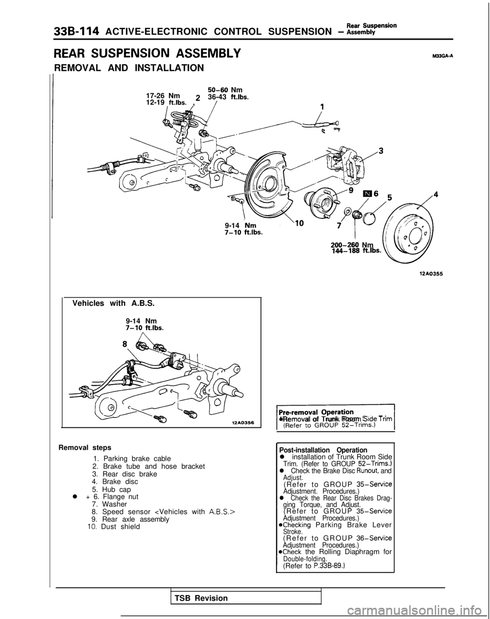
Removal steps1. Parking brake cable
2. Brake tube and hose bracket
3. Rear disc brake
4. Brake disc
5. Hub cap
l + 6. Flange nut
7. Washer
8. Speed sensor
9. Rear axle assembly
10. Dust shield 200-260
Nm
12A0355
%I*Removal of Trunk Room Srde Tnm
Post-installation Operationl installation of Trunk Room SideTrim. (Refer to GROUP 52-Trims.)l Check the Brake Disc Runout, andAdjust.(Refer to GROUP
35-ServiceAdjustment. Procedures.)l Check the Rear Disc Brakes Drag-ging Torque, and Adjust.(Refer to GROUP
35-ServiceAdjustment Procedures.)achecking Parking Brake LeverStroke.(Refer to GROUP
36-ServiceAdjustment Procedures.)@Check the Rolling Diaphragm forDouble-folding.(Refer to P.33B-89.)
TSB Revision
Page 1067 of 1273
33B-128 ACTIVE-ELECTRONIC CONTROL SUSPENSION - fi%?d Va’ve and
7-11 Nm5-8 ft.lbs.
4-6 Nm
3-4 ft.lbs.
Pre-removal Operation
I-im\.j -7
l Removal of Trunk Room Side Tr(Refer to GROUP 52-Trims.)
Air tube
0
\ e7” tiB991229
1210280
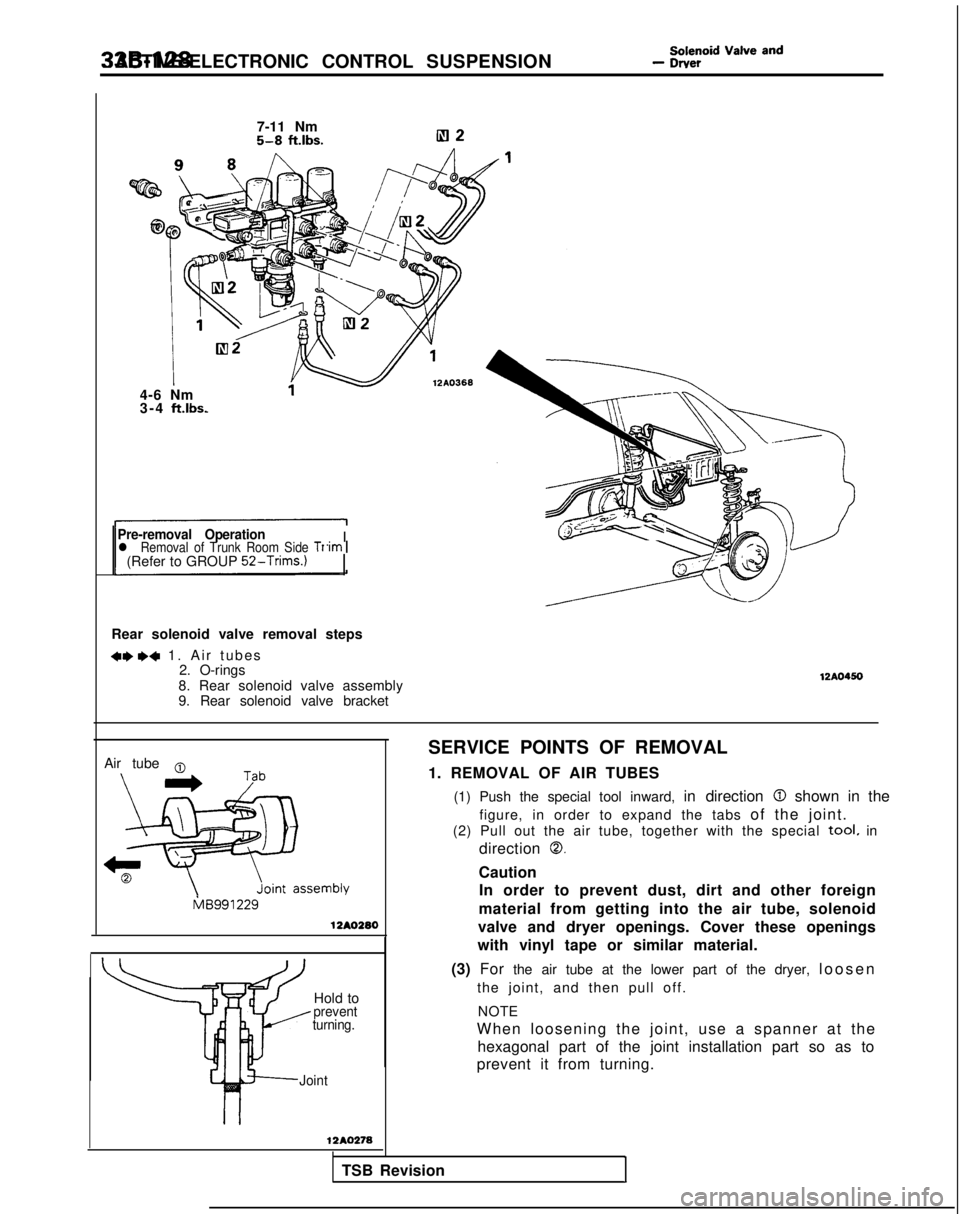
Rear solenoid valve removal steps
+e ,+ 1. Air tube
s
2. O-rings
8. Rear solenoid valve assembly
9. Rear solenoid valve bracket
12A0450
SERVICE POINTS OF REMOVAL
1. REMOVAL OF AIR TUBES
(1) Push the special tool inward, in direction
0 shown in the
figure, in order to expand the tabs of the joint.
(2) Pull out the air tube, together with the special
tool. in
direction
0.
Caution In order to prevent dust, dirt and other foreign
material from getting into the air tube, solenoid
valve and dryer openings. Cover these openings
with vinyl tape or similar material.
(3) For the air tube at the lower part of the dryer, loose
n
Hold to
prevent
turning.
the joint, and then pull off.
NOTE
When loosening the joint, use a spanner at the hexagonal part of the joint installation part so as to
prevent it from turning.
Joint
12AO278
TSB RevisionI
Page 1079 of 1273
338-140 ACTIVE-ELECTRONIC CONTROL SUSPENSION - t:%%%=mb’y’
INDICATOR ASSEMBLY
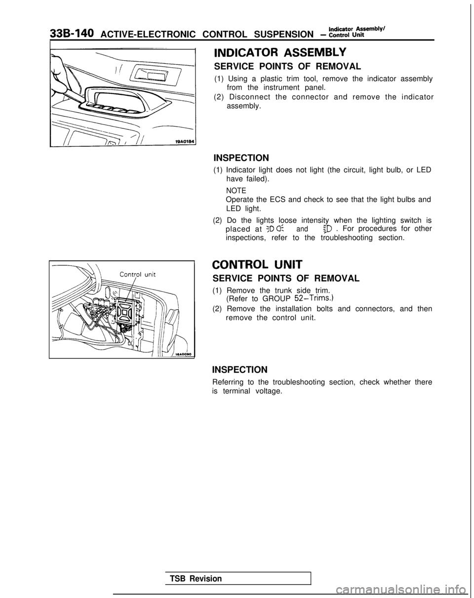
SERVICE POINTS OF REMOVAL(1) Using a plastic trim tool, remove the indicator assembly from the instrument panel.
(2) Disconnect the connector and remove the indicator assembly.
INSPECTION
(1) Indicator light does not light (the circuit, light bulb, or LED have failed).
NOTE
Operate the ECS and check to see that the light bulbs and
LED light.
(2) Do the lights loose intensity when the lighting switch is placed at
50 0:and$D . For procedures for other
inspections, refer to the troubleshooting section.
CONTROL UNIT
SERVICE POINTS OF REMOVAL
(1) Remove the trunk side trim. (Refer to GROUP
52-Trims.)
(2) Remove the installation bolts and connectors, and then
remove the control unit.
INSPECTION Referring to the troubleshooting section, check whether there
is terminal voltage.
TSB Revision
Page 1087 of 1273
34-6REAR SUSPENSION
- Rear Suspension Assembly
REAR SUSPENSION ASSEMBLY
REMOVAL AND INSTALLATION
10
17-26 Nm
12-19 “‘“s. y+.,
6 54 32w
dy4d
1
( t)e
._-.
l Removal of the Trunk Side Trim (Refer to
l installation of the Trunk Side Tnm (Referto GROUP 52-Trims.)l Parking Brake Lever Stroke Adjustment(Refer to GROUP
36-Service
Adjust-
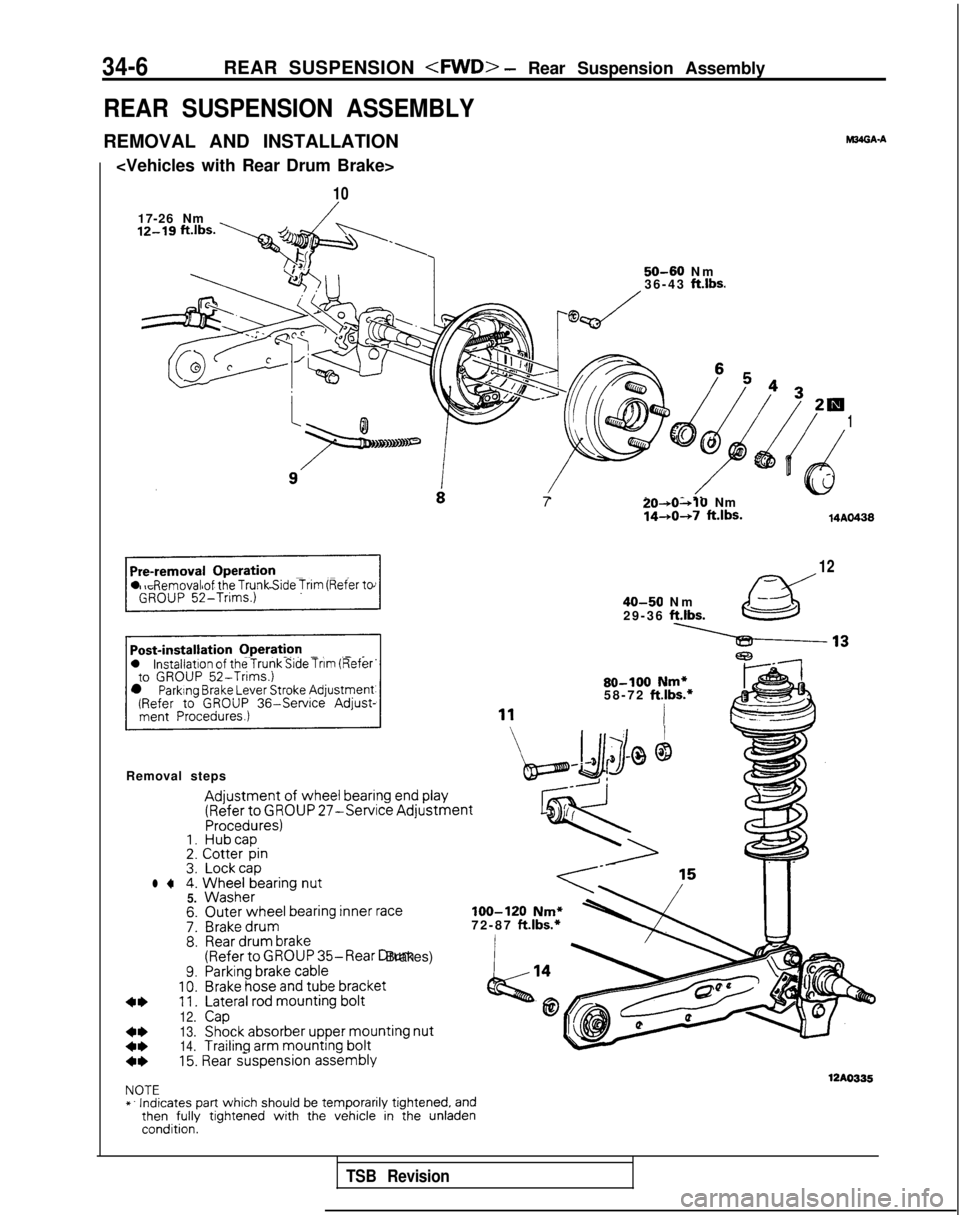
Removal steps
Adjustment of wheel
bearing end play
(Refer
to GROUP 27-Service AdjustmentProcedures)1. Hubcap2.
Cotter
pin3. Lockcapl 44.
Wheel
bearing
nut5.
Washer
7:8.
9.10.11.
12.
13.
14.
M34GA.A
50-60 N
m
36-43 ft.lbs.
Outer
wheel bearing inner
raceBrake drumRear
drum
brake(Referto GROUP 35-Rear Drum Brakes)Parking brake
cableBrake
hose
and tube
bracket
Lateral rod mounting
bolt
CapShock
absorber
upper mounting
nut
Trailing
arm mounting
bolt7
20-*0~10Nm1440+7 ft.lbs.14AO438
12
40-50 N
m
29-36
ft.lbs.
80-100 Nm*58-72 ft.lbs.*
I
loo-120 Nm*72-87 ft.lbs.*
4*15. Rear suspension
assembly
12AO335NOTE
*. Indicates part which should be temporarily tightened, andthen
fully
tightened with the vehicle in the unladencondition.
TSB Revision
Page 1092 of 1273
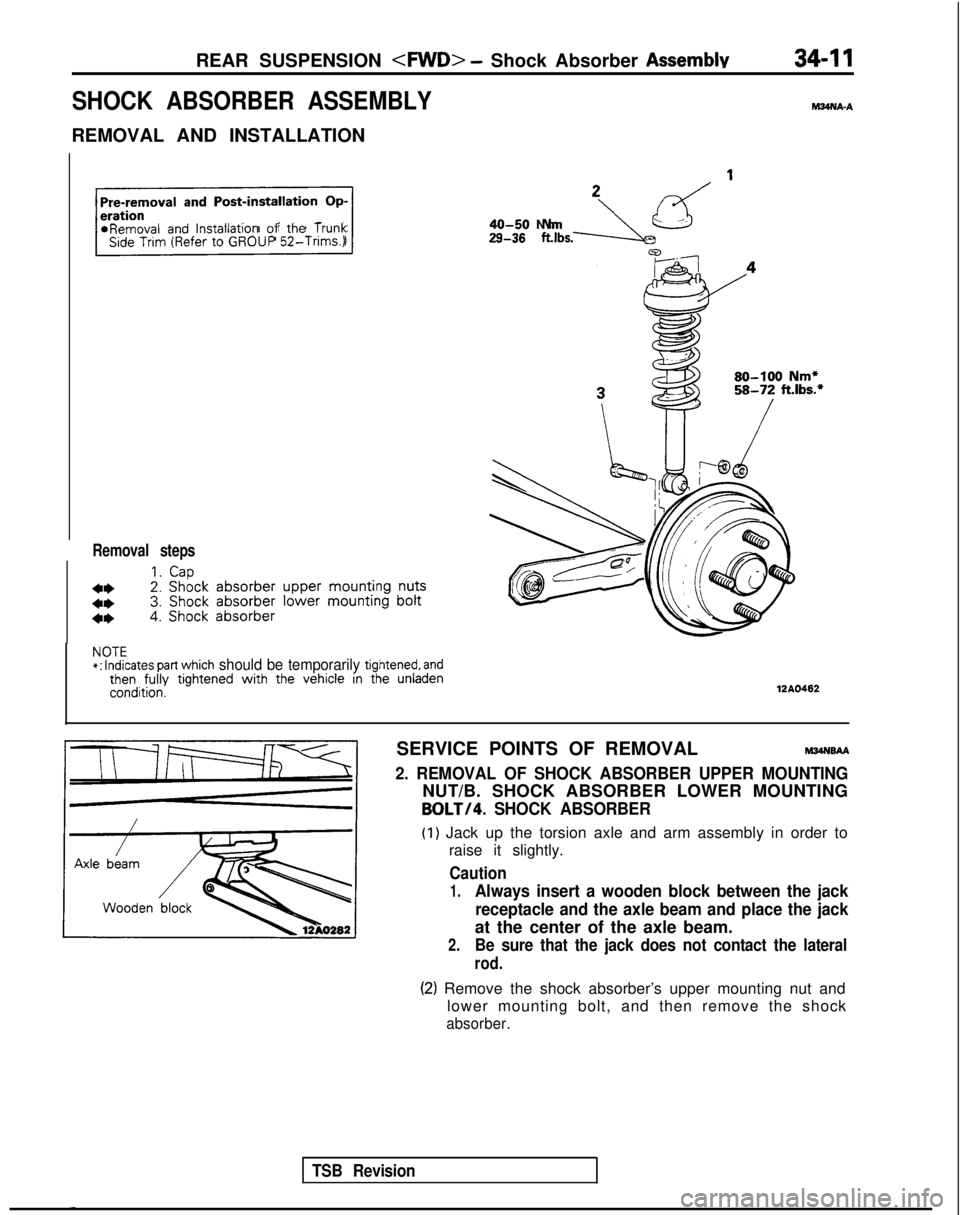
REAR SUSPENSION
SHOCK ABSORBER ASSEMBLY
REMOVAL AND INSTALLATION
hl34NA-A
Pre-removal
and Post-installation Op-
r
*Removal and lnstallatlon of the TrunkSide Trim (Refer to GROUP
52-Trims.)
Removal steps
1.Cap
4*2. Shock
absorber
upper
mounting
nuts
4*3. Shock
absorber
lower mounting
bolt
4*4. Shock absorber
29-38 .,bs.-JLzd ’40-50 N
m
80-100 Nm*58-72 ft.lbs.*
NOTE*:
Indicates part which should be temporarily tightened, andthen fully
tightened with
the vehicle in the unladencondition.12AO462
TSB Revision
SERVICE POINTS OF REMOVALM34NsAA
2. REMOVAL OF SHOCK ABSORBER UPPER MOUNTING
NUT/B. SHOCK ABSORBER LOWER MOUNTING
BOLT/4. SHOCK ABSORBER
(1) Jack up the torsion axle and arm assembly in order to
raise it slightly.
Caution
1.Always insert a wooden block between the jack
receptacle and the axle beam and place the jack
at the center of the axle beam.
2.Be sure that the jack does not contact the lateral
rod.
(2) Remove the shock absorber’s upper mounting nut and lower mounting bolt, and then remove the shock
absorber.
Page 1105 of 1273
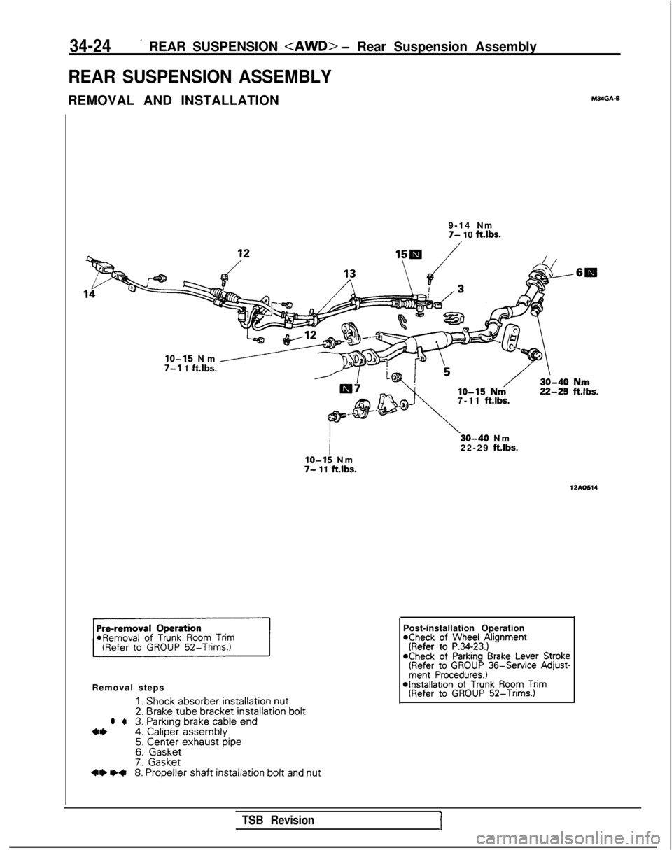
34-24’ REAR SUSPENSION
REAR SUSPENSION ASSEMBLY
REMOVAL AND INSTALLATIONM24GA.B
9-14 N
m
7- 10 ftlbs.
7-11
ft.lbs.
IO-15 Nm /7-l 1 ft.lbs.
Removal steps
1. Shock absorber
installation nut2.
Brake tube bracket
installation boltl +3. Parking
brake
cable
end4*4.
Caliper
assembly5. Center exhaust pipe6.
Gasket7.
Gasket** I)+8.
Propeller
shaft installation
bolt and nut
lo-15 N
m
7- 11 ft.lbs.
-30-40 N
m
22-29
ftlbs.
12AO514
Post-installation Operation*Check of Wheel Alignment(Refer to P.34-23.)aCheck of Parking Brake Lever Stroke(Refer to GROUP 36-Service
Adjust-ment Procedures.) *Installation
of Trunk Room Trim(Refer to GROUP 52-Trims.)
TSB RevisionI